My guess is most homebuilt owners with steam gauges have been seriously tempted by a glass panel upgrade—even if only to convince themselves that they really like steam better! I certainly had been contemplating an upgrade for many years. Having become accustomed to a Garmin GNS 530 in my Wheeler Express, followed by a recent upgrade to a GTN 750, I was inclined toward Garmin as the upgrade path. For the longest time my only option in terms of panel space was the G500/600, but that was out of my budget. When the G3X came out, it didn’t fit my panel well. And then—along comes the G3X Touch, at nearly the same time my vacuum pump was about due for replacement and the DG started precessing. I was already enamored with the GTN touchscreen.
It was a perfect storm—a couple thousand dollars in potential repairs avoided and the upgrade siren called out to me: “You can do this! And at almost no extra cost, considering the resale value of what comes out of the panel.” I had to do it!
Now I was on a collision course with some lingering concerns: Is a glass panel really better? Is it just a tempting distraction? Are some pilots seriously better off with steam gauges? To some extent it’s a personal decision, a comfort zone issue. To be honest, when I began the project, I wasn’t completely sure, but in the end, the old dog was able to learn some new tricks, and I have come to see the light (so to speak!)…but more on that later.
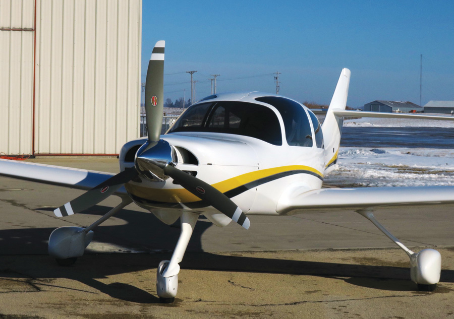
N49EX on a Chicago winter outing…Brrrrr!
System Choices
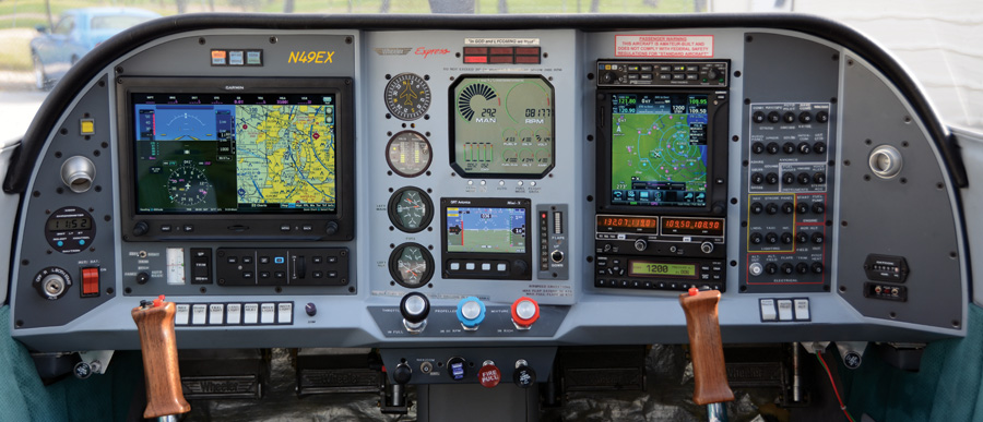
While there are clearly other excellent alternatives, the Garmin G3X Touch fit both my comfort zone and panel. I already had an S-TEC 30 autopilot, but decided at the same time to replace it with the Garmin integrated autopilot, which has much greater functionality, and yes, it provided the opportunity to sell a certified piece of equipment to help finance this gig. This is an amazing time in the world of homebuilding, given the recent appearance of non-certified avionics with capabilities so far out ahead of their certified counterparts.
Many homebuilders will be hesitant to perform substantial panel installations on their own. By all means, if you are not comfortable soldering, crimping, routing wires, etc., seek professional help. On the other hand, there’s nothing like accomplishing a challenging task, and hopefully in what follows, some may find enough useful ideas and inspiration to do it themselves. To me, it’s very satisfying, as well as confidence building to know as many details of your airplane as possible.
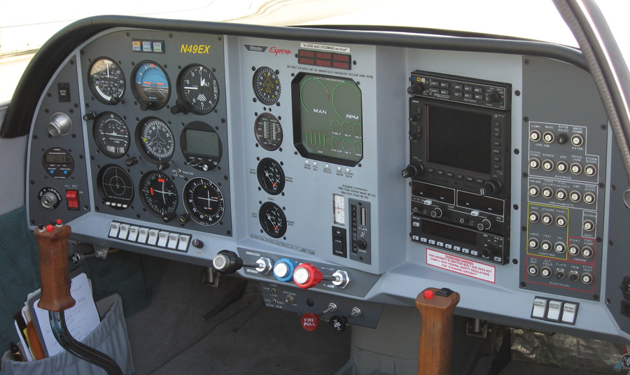
Steam gauge panel before upgrades.
Planning For Redundancy
The first step was to decide what stays, what goes, and how to provide redundancy with the new arrangement. In the panel right before the upgrade, in addition to the six-pack, there was the S-TEC AP/TC, a Rocky Mountain Instruments microEncoder serving double duty as a VSI, a Strike Finder, and two indicators for the Garmin GPS and KX-155. (Note the affirmation on the panel above the six fault indicator lights: “In God and Lycoming we trust.” That originated during an IFR flight passing over the Great Smoky Mountains, looking out the windows in sheer terror while weaving under a controller’s guidance through towering cumulus and lightning, watching the tops of mountains going by underneath!)
We’ve all been taught, and indeed there are regulatory requirements, to provide backups for key functionality, especially when flying IFR. I’m a big fan of doing what’s necessary and sufficient, and keeping it simple. Just because it can be done, doesn’t mean you should. I’m talking about glass panel designs that go to extremes—now all of a sudden there are three huge LCD displays! What’s that all about? Planning to open a stock brokerage in the sky? I contend that’s more of a distraction than useful functionality or backup.
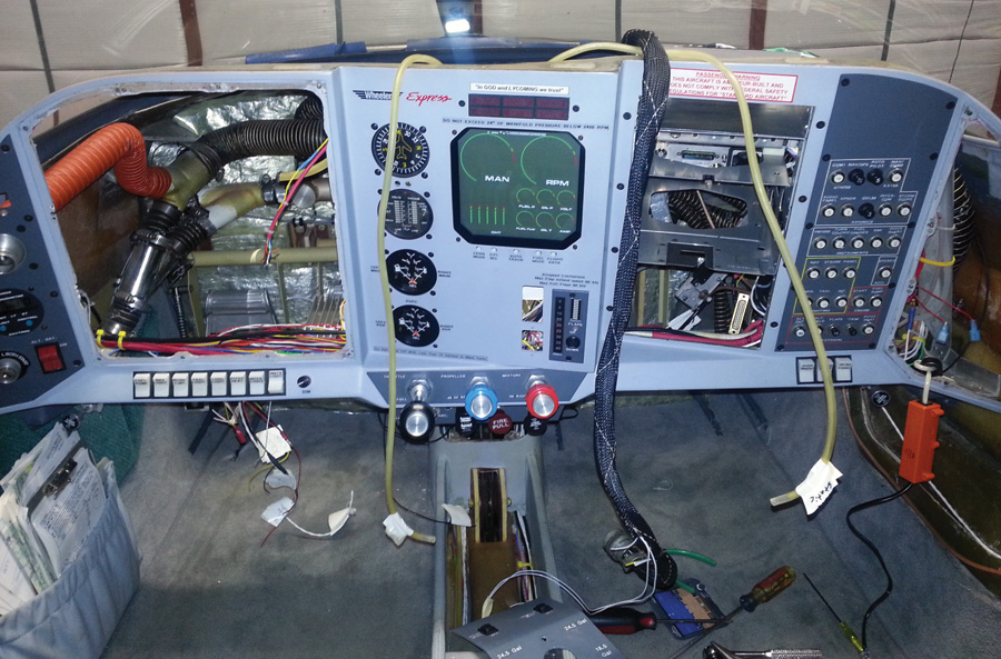
Dismembered panel.
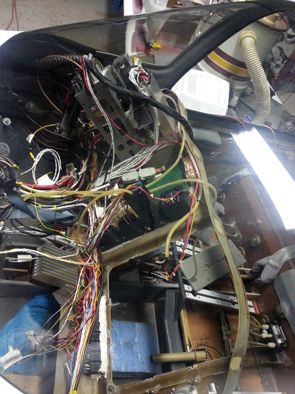
Not for the faint-hearted!
It’s easy to forget where we came from: The backup used to be the electric turn coordinator taking over for the vacuum instruments in case the vacuum failed. And of course, that was the most likely scenario—graphite vanes in that notorious pump suddenly deciding they would rather just be particles again!
Well, that turn coordinator is a pretty minimal beast, just enough to keep the dirty side down. And along with the compass, you might just barely know which direction you are pointed. I’m also not building a commercial airliner, and beyond redundancy, they have so much glass because they have two pilots seated five feet apart, and each would really like to see the same thing. That’s the long way of saying that one display unit is enough for me.
Still, you need a backup. So, the simple approach to glass cockpit redundancy in the early days was to keep the vacuum pump and the mechanical airspeed, altitude, and attitude. But once you adopt glass, going all electric seems inevitable. Then the question becomes what electrical backup scheme to pursue.
Here’s where I’m a staunch believer in keeping things simple. My electrical engineering sense is that an outright and sudden battery failure is highly unlikely, but alternator failures do happen. In fact, I have experienced one under IFR conditions. So, I chose to stay with a single battery, but added a backup alternator mounted on the conveniently vacated vacuum-pump pad.

Example mark-up of connector diagram for termination guidance and installation verification.
Similarly, a total bus failure is highly unlikely, and individual loads are protected and isolated via their circuit breakers anyway. For simplicity, I chose to stay with a single main and avionics bus structure. If you were to have a bus short, you would have a much bigger problem than loss of power—think fire and smoke! Also, a dual bus structure with simplex loads requires ORing diodes, which I am not particularly fond of.
A better investment is in care of how buses are mechanically placed and protected from shorting possibilities. On the topic of circuit breakers, as part of this upgrade I changed to all pull breakers, which allow you to isolate or shed load on demand. Items in the avionics block on top are on the avionics bus segment, while all the rest are on the main bus, the two being connected by the avionics switch. This isolates the avionics from engine-start transients. Note that both alternators power the main bus, and can therefore power everything. Normal bus loads will stay within the capacity of the backup alternator, but just in an emergency, load can be shed as needed by pulling breakers. With this approach, switching to backup is automatic, as the backup alternator regulation threshold is set just a bit below the normal charging regulation voltage of the main alternator. If the main alternator fails, the backup takes over automatically, and the switchover is annunciated by an LED in the fault indication display at the top of the panel.
The next key redundancy question is how to back up the PFD and associated ADAHRS functions, and for that matter, the G3X Touch display itself. Here again, the popular approach is to duplicate or triplicate the primary display. Instead, I chose to install a GRT Mini as the backup.
OK, I admit it: I also didn’t really have enough room for an additional G3X Touch display. But the GRT Mini as the backup provides some additional advantages. It presents software diversity, along with a completely independent ADAHRS and magnetometer, while having its own internal backup battery. This makes it completely independent of other aircraft systems in a pinch. If you choose to directly duplicate the G3X display, then it should be accompanied by duplication of the ADAHRS and power input to be truly effective redundancy and create fully separate fault groups.
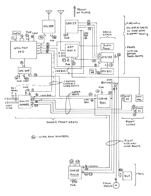
Pseudo-physical unit layout and wire routing diagram, top view of plane.
Key Challenges and Insights From the G3X Touch
OK, now that the system decisions have been made, it’s time to plan and execute the job. The G3X Touch installation is superbly documented in the Garmin installation manual. I cannot overemphasize the outstanding support the G3X team provides when you have questions. There were, however, several aspects of the job that provided particular challenges.
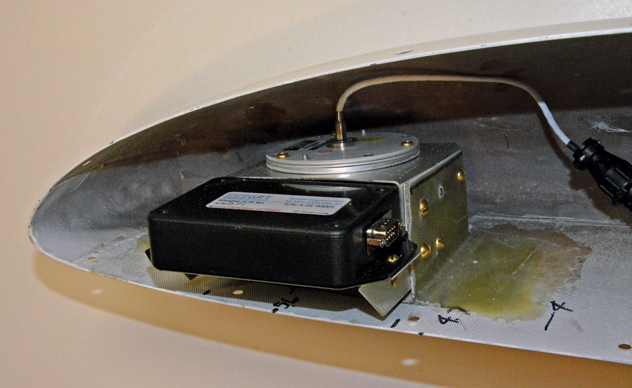
Garmin and GRT magnetometers mounted in the right wingtip—all fiberglass, aluminum and brass mounting and hardware.
First was where to mount the magnetometer. If you follow the guidelines in the Garmin manual strictly—what wires with what current levels to avoid with what spacing, etc.—you pretty quickly come to the conclusion there is nowhere acceptable. My joke in writing to the G3xpert folks was, “I’ve found the ideal location: back in the hangar.”
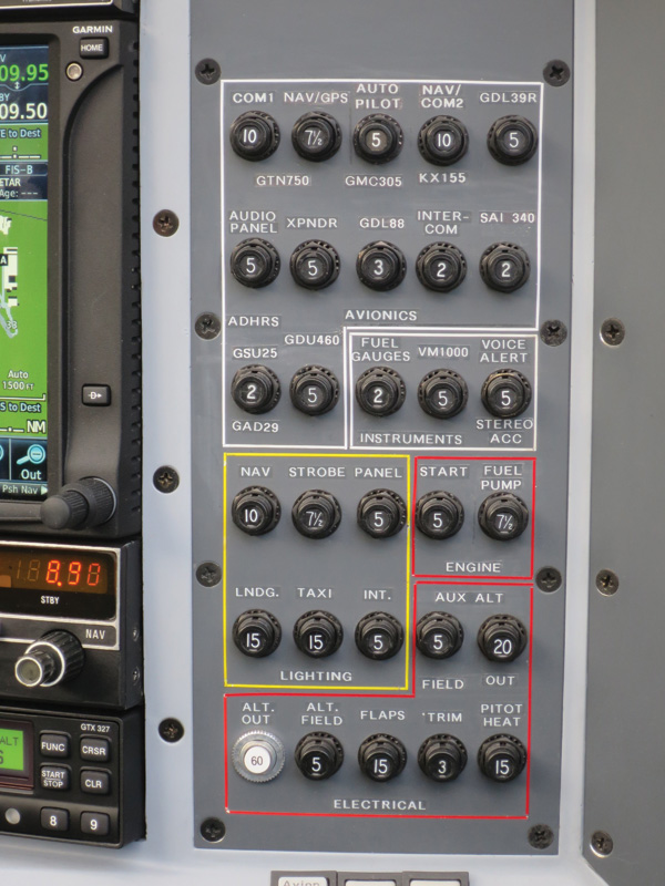
New circuit breaker layout—upper block is on the avionics bus—all pull breakers except for the main alternator output.
The truth be known, it’s not quite as onerous as the manual makes it out to be. In testing, I found that wires carrying currents were not nearly as great a concern as proximity of ferrous metal. I opted to go with a wingtip installation, and to my surprise, found a counterweight arm on the aileron that I had completely overlooked. It is made of steel, and being within six inches of the magnetometer was a significant violation. Garmin has an excellent acceptance test in the G3X maintenance mode that quickly identifies such problems. My suggestion is to run it soon, with the magnetometer only temporarily in a proposed location. A move of the magnetometer only about a foot farther forward in my wingtip eliminated the problem.
Another somewhat challenging task is the location of the ADAHRS module. In its favor, the module is conveniently small and flexible in orientation, but the location must be very stable and devoid of vibration. In particular, tempting as it may be, the instrument panel is highly discouraged. While the display unit itself offers a backside mounting for the ADAHRS, ending up on the instrument panel is not a good location. My chosen location on the wingspar carry-through handily passed the vibration test.
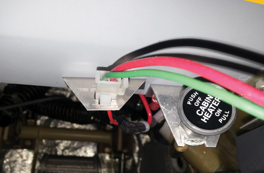
Aux power connector under panel—enables learning the complexities of new avionics without running the engine or running down the battery.
Wiring Techniques
Location of the remaining components is not so critical. Once they are decided, it’s time to plan the wiring.
An upgrade clearly has some unique characteristics that differentiate it from a clean-slate, brand-new installation. To start with, a bunch of stuff gets ripped out, and that warrants some careful planning. I made a list of all the wiring to be removed. Wires that are associated only with the removed equipment are easy. Others, such as the connections into the remaining GPS, are more complicated. I listed all the connector identifications and pin numbers to be removed. Then I carefully checked them off as I went along.
Some wiring, such as power feeds, can be re-used, so tagging them clearly is most helpful when the new wiring begins. Existing harnesses get unlaced along the way, and by the time the removal process is complete, you have one heck of a frightening rat’s nest. But don’t despair—it will all go together again very nicely!
Conventional wisdom is to do as much, if not all, wiring and harness creation off the plane and on a bench as possible. We’ve all seen the pictures of a fully equipped and harnessed new panel on a workbench, looking pretty as can be. But in an upgrade, that’s just not possible—a great deal of wiring will need to be done in place.
The approach I took was to make a wiring diagram that included all new and existing equipment, along with a rough physical placement and expected physical routing of the wiring. Individual wiring runs were assigned a number. (For example, wire trough along the right side of the fuselage, the center route from panel to console, etc.)
Next, I made a detailed list of every wire to be installed in tabular form, including check-off boxes, the “run number” from the wiring diagram, wire type, colors, connector numbers, pin numbers, and notes. This can be retained as a handy reference for any future modifications, or God forbid, troubleshooting.
Using the physical drawing as a guide, I made a rough measurement in the plane of every run, giving each a bit extra just in case (There’s an old German saying: Three times cut off and still too short!). For any particular route, say from the G3X display unit to the ADAHRS, the same measurement is valid for all wires in that run. These lengths were entered into the wiring table, which was also used to calculate how much of each type of wire to buy. To further assist when actually building the harnesses, as well as checking the job later, I took Garmin’s connector diagrams and marked them up with the wiring that would be done at each one. It’s somewhat redundant, but that often helps catch slip-ups.
Now, we’re ready to start the wiring. Since most of the wiring will become part of an existing harness, final end-to-end lengths will need to be determined in place, if you would like your finished harness to look somewhat neat. Going down the wiring list, terminate only one end of each wiring run at a connector associated with the new equipment. The Garmin instructions are quite clear and comprehensive on best practices here; it’s interesting to see the carry-over of discipline and style from the Garmin certified product documentation.
Once these partial harnesses are ready, it’s time to head for the plane. At this point, I temporarily plugged each connector into its LRU (line-replaceable unit)—the GDU 460 display, GSU 25 ADAHRS, both GA 28s, the magnetometer, GMC 305, GAD29, and GDL 39A.
For each run already terminated at one connector, I systematically went down the list and ran the wire in its bundle, cut it to length, and terminated it in the other connector. Power feeds from the circuit breaker block were similarly laid into their bundles to determine length, then cut and terminated. One last thing at each connector is to give each wire a decent—but not damaging—tug to ensure that the crimp is solid and the pin is properly seated in the connector shell.
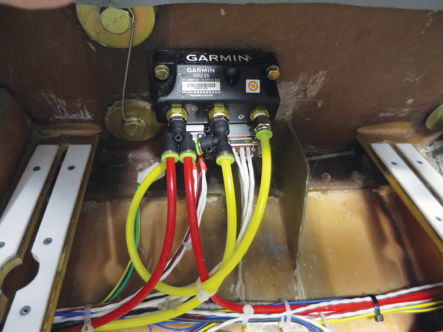
ADAHRS mounted on wingspar carrythrough, a pretty vibration-proof and central location—under/behind pilot seat, seat rails to either side.
Checking, Testing, and Bring-Up
This is where the real fun begins! The one thing you really do not want to do is let the smoke out of these wonderful new (expensive) toys. Now’s the time to take your time, relax, and check everything very carefully. Here’s where the mark-ups of the connectors from the Garmin installation manual come in again. As such, this is somewhat of an independent audit that will catch any errors in the wiring table.
I made a set of probe wires from leftover connector pins or sleeves, and used them to check connections at each connector, using the LRU connector diagrams again as the guide. First thing at each connector is to verify the proper pin populations, then move on to check connectivity, the first being power. I have a line power supply that I can plug into my airplane bus to not run the battery down, and I used it to energize plane power.
Start with all the breakers pulled. Then at each LRU connector, verify the power pins and correct associated circuit breaker with a voltmeter and check ground connections with a buzz to ground. These are the most important connections to check, but verification of other wiring is important to avoid damage and at least minimize or eliminate any later difficult troubleshooting. At a minimum, I recommend checking the full CAN (controller area network) bus connectivity. In my case, I also checked every new wire connecting into the GTN 750—too many dollars involved there to take any chances!
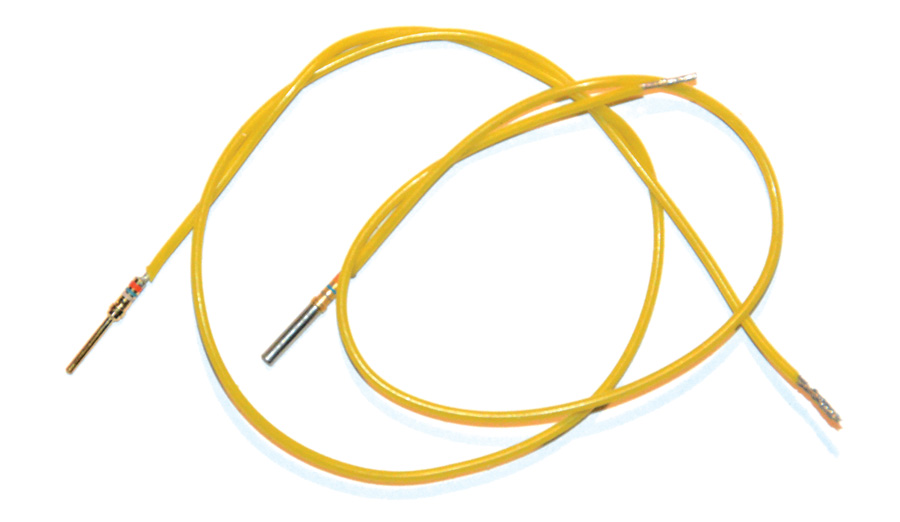
Male and female connector verification probes.
Now it’s time for the big moment of reckoning. Start with individual circuit breakers and the display unit, and see that it initializes properly. Here again it’s virtually a necessity to have an external power supply so that you can leisurely perform the variety of bring-up tests and configurations. I find it useful also for just sitting in the plane to learn your new electronics, play with them, enter flight plans, etc. My auxiliary power connector is located under the right bottom of the instrument panel.
Once everything powers up, it’s time to perform unit and data link configurations so all the pieces can talk to each other. This can be a bit tricky. The Garmin manual specifies the configurations on each page of their general wiring diagrams for each LRU.
To organize the process, I copied each of the applicable pages and marked the pertinent items, as well as made a table of all the configuration data. While being a duplicate, it is a good future consolidated reference of how the system was configured. The tricky part is that this requires you to ensure that all connected existing equipment is up to the latest software version, and also that you verify both the connections and configuration associated with connected LRUs that seem a bit questionable as you look at the Garmin diagrams.
For example, the connections and configuration of my recently installed GTX 327 transponder were not correct in the current installation manual. New transponders do not need a direct connection from the ADAHRS for air data, but rather will get it automatically via the ARINC 429 link through the GPS. These nuances may vary depending on your installation, and I encourage you to seek clarification with the Garmin folks where necessary.
Flying It
Everything up and running? Passed the vibration and magnetic interference tests? Ground calibrated the magnetometer? OK, time to fly!
I have to admit, the first flights involved a certain amount of trepidation, especially since I started out not completely sure of this whole thing. In fact, I made my first flights with the old ASI and altimeter temporarily patched into the pitot/static system and taped to the bottom of the panel, as a transition aid. And I have to admit, the first couple of flights I couldn’t help but look down to them occasionally, especially on takeoff rotation and landing. It takes a bit of practice to develop the intuitive sense of critical airspeeds and altitudes from the tape presentations that were captured in a glance at the round instruments. However, it didn’t take long to become comfortable and realize the many advantages of the new technology. Once you train yourself to absorb key information at a glance from the different presentation, it becomes clear how much more is packed into a tighter space and how it simplifies the scan.
One additional challenge I encountered was in tuning the autopilot. For the most part, its performance was immediately excellent with minor tweaks to the gains, except for an altitude hunt of some +/- 30 feet that I could not get rid of.
It turns out that the ADAHRS pressure sensors are exceptionally sensitive, and the static pressure delivered by my pitot tube static ports was not stable enough. In other words, slight pitch changes to hold altitude resulted in disproportionate pressure changes due to the angle changes of the pitot tube, resulting in an altitude oscillation.
This problem was never apparent in the altimeter before, but certainly noticed by the new autopilot. As a test, using cockpit air stabilized the altitude hold of the AP, but was unacceptable as a permanent solution due to not being the correct outside pressure and thus delivering incorrect altitude and airspeed readings at flying speed. So, psychologically hard as it was, I had to drill some holes in the fuselage and add side static ports, similar to what you find on many certified craft. If you have a pitot tube that includes the static ports, you may encounter the same problem.
Now that I have become used to flying with the new glass, here are a few final thoughts: This stuff is so pretty and enticing that I suggest you make a concerted effort to teach yourself to keep your eyes outside the plane as much as possible and use the glass only as is functionally needed, not as is possible. Back in 1964, Marshall McLuhan warned about television that, “The medium is the message.” It applies as much today to glass panels in airplanes.
Finally, with a radically different redundancy scheme, practice failure modes. Whatever backup scheme you chose, become comfortable with reduced configurations and alternate displays.

![]()
Reinhard Metz built his Wheeler Express over an eight-year period and has been flying it for 16 years. He is a retired Bell Labs electrical engineer and has a second career in commercial food equipment. Reinhard lives in Wheaton, Illinois, and often flies out of DuPage Airport with his aviation enthusiastic daughter Ashley. Reinhard can be reached at [email protected].


where did you get the fiberglass panel for your wheeler express from?