The transponder is one of the oldest items in any airplane. It had its genesis in the WW-II top secret IFF (Identify, Friend or Foe) system whereby Allied aircraft returning from a mission in mainland Europe would respond to an interrogation on one frequency by returning a secret code of the day (there were 64 of them) on a separate frequency. Return the wrong code or fail to return any code at all? Be prepared to meet some of your closest friends in Spits, Hurricanes and Mustangs until they figured out that you were one of the good guys.
Post-War Repurposing
After the war ended, civilians took the IFF system and adapted it to civilian aircraft. Why? Because plain old radar would “paint” you on the radar screen if you were close enough and if the radar had enough power. Remember that the power of an RF signal diminishes as the square of the range, and the reflected signal diminishes as the square of the range, leaving the returned signal to the search radar with about a quarter of the power term in it. Which is to say that the signal drops off dramatically with range.
Not only that, but also all the radar knew was that there was a large chunk of aluminum somewhere in the airspace. It had no clue who it was seeing, where it was going or what its altitude was. Some of you who had wings back in the day may remember when we were told to turn 90 left, then 90 right for identification. And there was always some yo-yo up there who would make the turns right along with you to confuse the poor joker monitoring the radar.
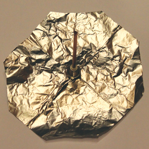
The “Reynolds” ground plane of aluminum foil. If you need a rigid one, glue this to a lightweight flat substrate (insulator or conductor).
At any rate, the current crop of transponders have 4096 discrete codes that you can use (4096 = 212 which lets us set codes digitally) plus a plug that lets us connect an altitude encoder that (also digitally) transmits a series of pulses upon interrogation from the ground radar that not only identifies our particular aircraft, but prints out our pressure altitude (altitude with the altimeter set to 29.92 inches) as well. The ground radar interrogates our transponder on a frequency of 1030 MHz, and your transponder spits out a pulse train at 1090 MHz with a hundred or so watts of peak power. The average power is only a few watts, but it is the peak power that determines range.
What About the Antenna?
All of this is really immaterial until we provide the aircraft with an antenna that both receives the interrogation and spits back a reply. For the last 30 years or so, I’ve concentrated on the VHF-UHF, GPS and loran antennas, not saying much about the transponder antenna. However, this last month’s mailbag contained a half-dozen comments and questions about transponder antennas. Given this relative outpouring of interest, I decided to see if the transponder antenna could be made as easily as all of the other antennas mentioned above. Fortunately for us, it can.
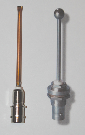
The transponder antenna on the left costs about $20 to make. The one on the right costs about $100 to buy. Your call.
Now I don’t claim that this antenna is any better than the store-bought transponder antenna, nor will I assert that it can be mounted on a supersonic airplane and survive. But it looks to me like it can at least survive our metal puddle jumpers on the outside of the airframe and be easy to locate on the inside of the airframe on composite ships. And it costs less than $20 to build from scratch.
It really isn’t rocket science to build, but for those of you who think cutting metal to 50 mil tolerance is something to be proud of, be advised that each 10 mil of error on the radiating element one way or the other misses the center frequency (1090 MHz) by 5 MHz. If you must err, do so on the side of too long rather than too short.
I fabricated the radiating rod out of 0.125-inch outside diameter copper tube with 0.014-inch wall thickness, giving a tube inner diameter of 0.097 inches. The BNC connector shown has a center conductor OD of 0.090 diameter, giving a slip-fit to the copper radiating rod. Simply solder the rod to the BNC center conductor terminal.
How long do we make the copper rod? The computer program I use to design antennas says that it needs to be 2.54 inches long. However, this doesn’t take into account the height of the center conductor above the grounded surface of the BNC connector, which is 0.100 inch. That’s the height of the little white insulator shown in the photo, so I made the rod itself 2.44 inches long.
Tying Up Loose Ends
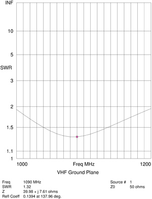
The plot of antenna “goodness” over frequency. “Goodness” is the lowest point on the curve, which here is at 1090 MHz with an SWR (standing wave ratio) of 1.32. Anything below 1.5 is excellent with the receive SWR at 1030 MHz at 1.58.
I had a good, hearty laugh at the literature from some of the antenna manufacturers that claimed the little silver BB on the end of the antenna was an “end loading element.” Horsefeathers! I put a so-called top-hat loading element onto the antenna software, and with the exception of making the antenna itself a bit shorter, there was absolutely no difference in the performance curves for the antenna. My take? The early commercial antennas didn’t have this top BB, and somebody put their eye out on the sharp end of the antenna and sued the antenna manufacturer. Hence the “top loaded” BB. I squeezed the top end together and soldered it shut, not so much for electrical performance but to keep the little creepy crawlies from getting inside the tube and making nests. If you prefer, once it is up and running, put a plastic switch cap onto the loose end purely for the looks, not for the performance.
Some tips:
• If you cannot find copper tube, brass tube from your local hobby shop will do; expect a slight loss in radiation efficiency.
• We could have split the difference between transmit and receive efficiency by centering the antenna at 1060 MHz (halfway between the 1030 receive and 1090 transmit frequencies), but my experience is to get the maximum power out of your transponder and let the ground unit that is putting out kilowatts worry about getting the signal to your airplane.
• Paint it? Sure. Just mask off a thin stripe around the white BNC connector insulator so that there is an insulation path between the connector ground and the antenna rod.
• Use a connector other than BNC? That’s OK, but you as the design engineer have to find copper tube to match the center conductor. And, by the way, the OD of the copper tube sets the bandwidth of the antenna; use a smaller diameter tube and the SWR goes up concomitantly.
• This antenna needs a ground plane. If it is the skin of a metal ship, that’s fine. If it is mounted inside a plastic airplane, you will need to fabricate a ground plane. Note that the photo shows a “flexible aluminum” ground plane made out of aluminum foil. If you are trying to save weight, aluminum foil is every bit as good as quarter-inch aluminum plate. The circular and octagonal versions are absolutely equal in performance.
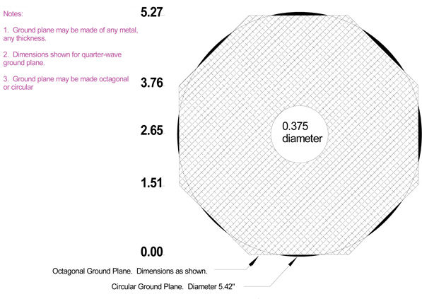
The ground plane dimensions.


s")


