
In the past couple issues we’ve covered a number of steps you might undertake while upgrading your instrument panel. At this point we’ve discussed theory, budget, layout, and cutting your panel. In this installment we’ll take a look at what most folks think of as the scary part—that being the wiring of your new goodies.
While wiring your own avionics may seem to be a daunting task, there are steps you can take which will make the task easier, safer, and also make future maintenance or upgrades less stressful.
Where to Start Before You Start
Like everything with flying, time spent up front planning will pay off in spades down the road. For wiring, this means coming up with a plan before you ever run a single wire. The easiest and best thing to do is simply make a diagram. This can be accomplished in several different ways. If you’re comfortable with a computer, then the first option is to use a CAD program or other drawing tool. I’ve seen some wonderful drawings made in just about every program out there by various individuals. If you’re not comfortable with the computer, then the second option is to do it the old-fashioned way and get a pencil (notice I didn’t say pen) and some graph paper. The third option is to simply pay someone to do a drawing for you. A number of shops, including ours, will make you a large-sized customized drawing based on your avionics for a couple hundred bucks. No matter which method you choose, the end goal is to have a diagram that shows each avionics unit in your panel, each connector on each unit, and each pin number for each connector, and lastly, the associated wiring between said units.

Using correction fluid or colored marker to identify key pin locations (in this case every 10th hole) makes finding and counting the many holes on a connector much easier.
This task is not hard, but it can be time-consuming. Before you start, make sure you gather up all the installation manuals for the units you plan on installing. Most manuals will have a section that details the pinout of the unit, as well as one or more wiring diagrams for the unit. The “gotcha” with figuring out what goes where is that different manufacturers sometimes call the same function by different names. This can be challenging and is something you’ll just need to work out, as there is no secret decoder ring for all the terminology. That said, we’ll give you a simple list which might help you.
• PTT = Push to Talk = Mic Key = Mic Transmit = Transmit Key.
• Mic Audio = Microphone Audio = Mic Audio Hi = Mic Hi.
• Comm Audio = Radio Audio Hi
• Headphone Audio = Phones
• Anything “Lo” typically is a ground.
• Anything “Hi” typically carries a signal.
• RS-232 = serial (typically).
• Remember, with RS-232 and ARINC429, they may have both an “in” and an “out.” Never hook two “ins” together. You always hook one “in” to a different “out.” Sort of like a pitcher and a catcher, one sends, the other receives. If you hook two “ins” together you’ll likely get an error or something won’t work.
• Sometimes you don’t have the same number of “Lo” grounds between units, therefore, you may need to share them.
• If your document calls for shielded wire, use it (or likely regret it).
Once you’ve gathered up all the manuals and made yourself a list of components, you will next start drawing out all of the interconnects and wiring for each unit, as well as between the units. Start with the simple stuff. I’d recommend doing it in the following order:
1) Power and Grounds—note the fuse/circuit breaker size required on your drawing.
2) Simple RS-232 Serial lines (like air data for a transponder from an EFIS or encoder), GPS lines from a GPS to an EFIS, ELT, autopilot, etc.
3) ARINC lines between things like a GPS, autopilot, EFIS, transponder, etc.
4) Audio lines from various boxes to your intercom or audio panel.
5) Interconnections between your various EFIS and any remote boxes.
6) Audio panel or intercom—start with the jacks first, then add in other devices.
7) Stick grip trim and interconnects to any displays, radios, transponder, etc.
8) Any analog interconnects (like a VOR/CDI/GS display).
As you work through your drawing, you will notice that occasionally things will share various wires, and sometimes you need to indicate a splice or “tee” in the system. Make sure you notate any splits, tees, or splices on your diagram. Also note the different types of grounds (audio grounds verses airframe grounds, for example).
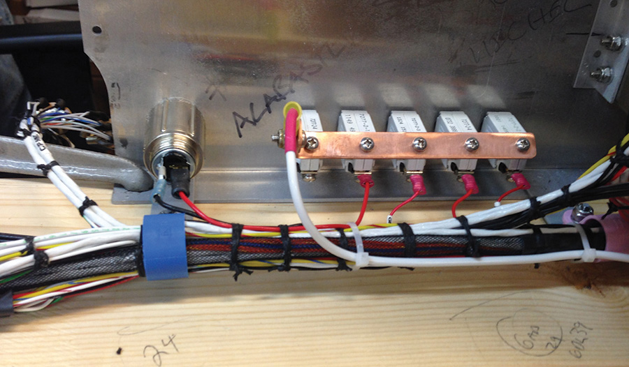
Temporary use of cheap zip ties helps keep wiring bundles neat and tidy while you are fabricating harnesses. As the harness grows, just cut off the old zip ties and use new ones. When finished remove the zip ties and replace with lacing cord.
Once you think you have the drawing finished, walk away from it for at least one day, then come back and look at it again. You likely will have missed something or need to tweak it. If possible, have a friend (either in person or online in a forum) review your drawing for any discrepancies. That can really save your bacon because sometimes one incorrect wire can cause all kinds of havoc and wonky glitches in your avionics!
The last step before you actually start wiring follows the old “measure twice, cut once” mantra. In the case of wiring, sometimes we have good information on the wire lengths for items placed in the instrument panel, but with remote boxes, it can often be difficult. I get calls weekly from folks asking, “How long do you make the wire for XYZ”? There is no answer that is correct because, of course, most every person will route things differently in their own airplane. In order to get an accurate measurement, a good trick is to simply route a piece of string (or fishing wire, or twine, or cable, etc.) where you intend to run the actual wiring in the plane. Once you’ve run the dummy wire/cable/string, you simply remove it from the airplane and measure it (then add an inch or three!).
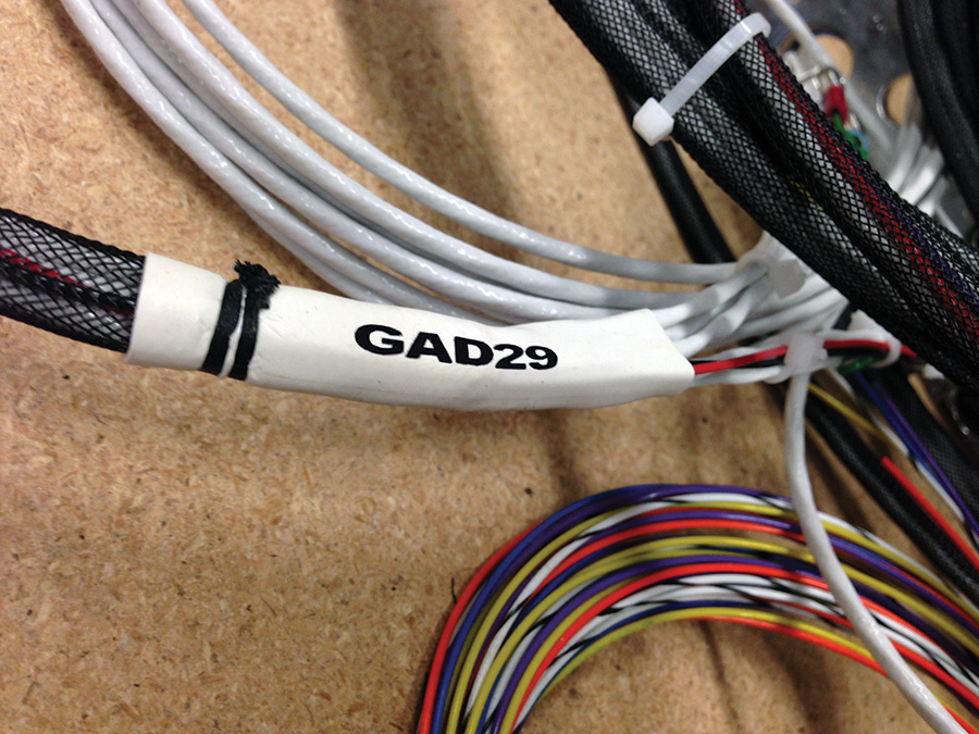
Simple shrink tubing can be used to label various harnesses. Write on the tubing with a marker and then shrink it.
More examples of shrink tubing labels used to identify various wire leads.
Making the Bundles
Finally, it’s time to cut some wire! This is the fun, but somewhat tedious, part of the project. By now you should have figured out how and where you’re physically going to mount everything, planned out the interconnections on some sort of diagram, and purchased the necessary raw materials (wire, terminals, crimpers, strippers, spare pins, heat shrink, cable, etc.). There are basically two ways to go about wiring this (actually three if you count wiring the units inside the actual airplane as an option, but we don’t like that very much at all, so I remove that as an attractive or viable option). That said, you can’t avoid all work inside the airplane—just the nitpicky and tedious part! The first two ways both involve doing the wiring on the bench (or kitchen table, or wherever).
Use a marker on the back of the panel to label various things temporarily. Also shown is lacing cord after zip ties have been removed from a harness.
Your first choice is to wire everything in an actual panel (real or mocked up) on your bench/table. The second choice is to wire up just the connectors themselves without the actual panel or trays in your possession. In both cases, put the units (or connectors) in their respective places, then either mount the entire conglomeration to the bench, or set it upside down. Either way is fine; just make sure you physically fasten it to the bench. I’ve done something clumsy like catch a loose wire on my shoe and yank the entire project off the table—not a good thing for multi-thousand-dollar electrical devices! If you don’t have a panel or racks, and are just doing the connectors, a piece of pegboard works very well. You can use the holes to put small dowels, zip ties or other devices in place to hold your wiring as you go.

With the panel mounted on the bench, easy access to all sides will make programming, troubleshooting, and setup easy.
One last thing before you begin to actually run wires. Plan on a service loop behind devices that are removable (especially thing like EFIS screens) from the front of the panel. A service loop is simply an extra loop or half loop of wire behind the device. The reason for this is it allows you to pull the EFIS screen (or other device) out of the panel towards you far enough that you can simply reach back and remove the connectors without having to lie underneath the panel to try and disconnect the wire. Typically we like to see at least 6–12 inches of wire for this purpose.
Now you can finally start running wires. The trick here is to think of the entire project one wire at a time. Don’t think of it as dozens or hundreds of wires in huge bundles. That thinking is exactly how you’re going to wire your devices. Simply take your drawing that you previously made, grab a highlighter marker, and start picking off wires as your run them. Once you’ve highlighted every single wire on your drawing, you should be done!
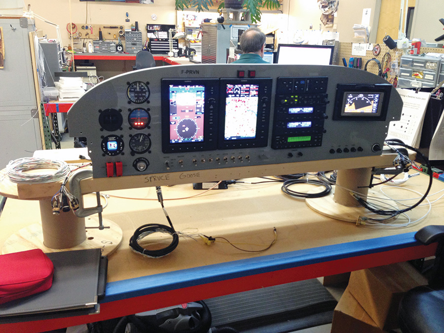
Mounting a panel on the bench with some temporary wood or other bracing will make it much easier to work with both front and back.
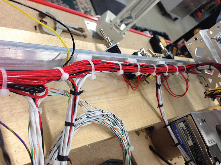
One thing I’d like to mention that can be somewhat of a touchy subject is neatness. I’m sure we’ve all seen the literal “rat’s nest/bowl of spaghetti” wiring mess before. Besides the fact that it is just unsightly, it makes working on things terribly difficult, and in some cases it can be a safety hazard. Therefore, I’m encouraging you to take your time and make it look pretty. It usually takes the same amount of time to make ugly wiring harnesses as it does to make nice-looking, neat wiring harnesses. Plan on using tons of small zip ties to temporarily hold wires in place as you add them. Since they only cost something like a penny each, don’t be afraid to use a ton of them as you run wires. Pay attention when you run wires in a bundle—if you can keep the wires nicely arranged, you’ll have a nice “combed” harness where you can easily trace wires from one point to another. This is the beauty of doing this “one wire at a time.” As a harness grows in size, the radius of each wire around corners will change. Going wire by wire will allow you to slightly adjust each wire as you install it and keep everything nicely arranged.

Temporary clamps can be used to hold a panel on the bench. Make sure to cover the clamp points with tape to prevent marking your panel.
Check it Out
Done? Nope, not yet. Just because you’ve run all the wires doesn’t mean you can throw everything into the plane and go fly. One last step is imperative: double-check your work. Many, many times I’ve seen the simplest of errors go unnoticed and cause someone to ruin thousands of dollars of avionics. Something like mistaking the front for the back of a connector (in which case the pin numbers would be mirror images) can ruin your day. The most important things to double-check are the power and ground wires and ensure they are going to their proper places. In our shop my technicians give themselves a head start by using a “correction fluid” type pen to circle key pin holes on the connectors before they ever start. This gives a nice visual representation of a specific pin number without having to revert to a magnifying glass to read those infernal tiny numbers on the connectors! If possible, spend a few minutes with a multimeter and just do a quick check to make sure there are no pins going to “ground” that shouldn’t go to ground (test each pin to ground). This is a quick bit of insurance.
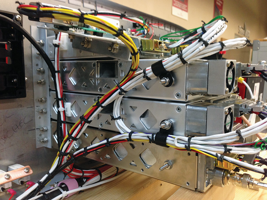
Using nylon clamps and lacing cord will ensure tidy and secure wiring to and from your radio stack.
Test it Out
Last step before you actually put the stuff in the plane: turn it on and test it. Make sure all the magic smoke stays in the wires, and the units are at least behaving in principle the way they are intended. Granted you may not be able to do an entire and thorough checkout, but you can make sure things boot up properly and also that they are talking to each other (if you wired multiple units) as designed. Here are a couple quick hints before you test everything out (this applies in the plane or on the bench).
Temporarily mounting various remote boxes while wiring them up on the bench will ensure your wire lengths are correct and there will be no surprises during final installation. Note the use of zip ties once again as temporary restraints for harnesses.
1) Ensure you have the proper electrical supply voltage. Low voltages on batteries, chargers, and other associated devices have caused people more lost hours and pain than I care to remember. Voltage too high can be just as bad!
2) Plug in antennas to the certain devices—specifically transponders and radios. Not doing that can inadvertently lead to you destroying them (sometimes without you even pushing any buttons or doing anything specific).
3) Pull all circuit breakers and/or fuses before you connect power to your equipment. Only then can you turn on power, and slowly energize one unit at a time. This will hopefully keep you from blowing up an entire plane’s worth of electronics, should you have a catastrophic mistake with your wiring.
4) Let the equipment run for a good number of hours. Electronics will typically die an “infant death” if there is a problem. If they run for a number of hours (4–8) you’re usually good to go.
5) If your GPS shows an error message, don’t be alarmed. GPS units have a difficult (and many times impossible) ability to “see the sky” in your hangar, shop, or house. Running the antenna to a window can help, but is not a guarantee.
6) If you hear static in your radio, don’t immediately assume you have an issue. First, turn off any fluorescent lights, TVs, and other radios. We’ve had many a customer with “radio issues” that turned out to be interference from other devices in their buildings.
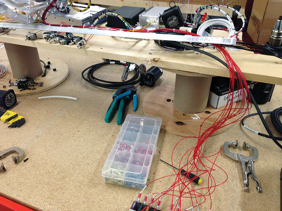
A simple piece of scrap aluminum angle or tubing used in the early stage of creating a wiring bundle will ensure that the routing of the wires all remain neat and well grouped.
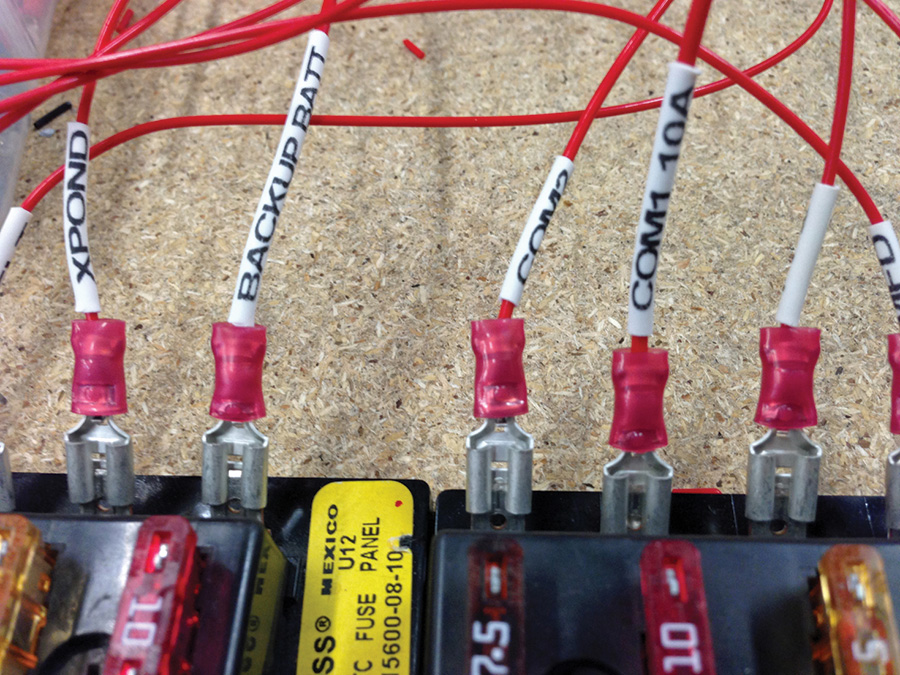
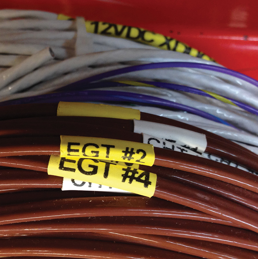
Labeling each wire as it attaches to circuit breakers and switches makes future maintenance much easier. These are more shrink-tubing labels.
Done
That’s about it. Plan it, measure it, wire it, test it, and install it. Not much to say about the actual installation into the airplane because that’s usually the easiest part of the job. If you spent the time on all the earlier steps, putting the stuff into the actual airplane ends up being pretty anticlimactic. Hopefully some of these hints and tips will help you on your way to upgrading your panel and installing new goodies in your plane. One thing I didn’t spend much time on, but is perhaps the most important of all, is what we call RTFM—”Read the freakin manual.” This goes for both installation and operation. Sure, they can be horribly boring and sometimes difficult to even understand. But again, this will pay off in spades. You will be much better informed both installing and operating, which will make using the unit much more enjoyable and safe. Have fun with whatever new goodies you are installing because once you get good at it, you won’t be able to resist doing it again when the next “latest and greatest” widget hits the market!


Hi, I have read through your write ups on how to wire up a an aeroplane as an Avionics.
Please I need help in understanding the blueprint wiring diagrams to wire up an aircraft electrical modification.
I have been struggling with this for a while now.
I cannot seem to find any videos or inormation online that can explain things better to me.
E.g which wire to remove or install, which solder sleeve goes on the connector, ground or in a splice
I will be glad if you can point me in the right direction.
Many Thanks