It started as a challenge: Craig Catto of Catto Propellers has built three wings for Formula 1 racers (Endeavor, Outrageous, and Scarlet Screamer). Though Endeavor has, of course, won gold many times in recent years, that wing was designed by Mike Arnold. So Catto took great pleasure when Vito Wyprachtiger flew Scarlet Screamer to gold in 2013 on a wing that Catto had not only built, but also designed. Attending the races with Catto was aerodynamicist Dr. Paulo Iscold, who consults with Catto on various engineering projects, and who holds several world speed records with his CEA-308. As Catto explained, “I said to Paulo, ‘Well it only took 12 years for my wing to win at Reno. Think you can do any better?’ By the end of the races we had a client who was willing to give Paulo a shot.”
For years Cassutts have dominated Reno Formula 1 racing—if not in speed, at least in numbers. Two-thirds of the entries at the 2014 races were Cassutts. They are tried-and-true airframes, and with tweaking can achieve respectable speeds. In fact before its fatal midair in 2007, Gary Hubler’s Cassutt 111M Maria took the course (but not qualifying) record from Jon Sharp’s Nemesis.
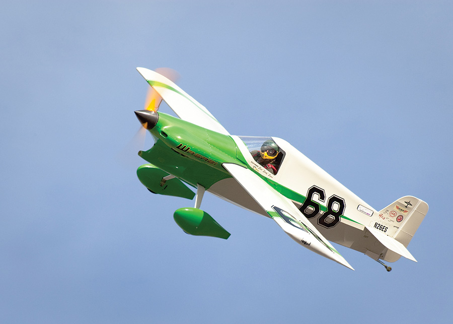
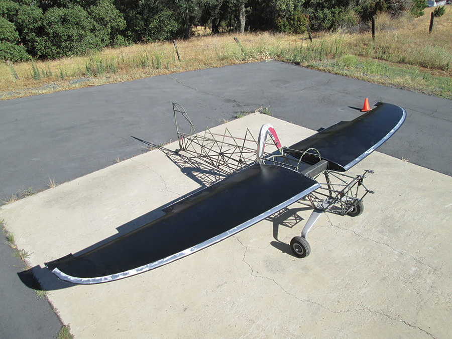
Elliot Seguin’s two Wasabis illustrate the evolution of F1 racing. His original Cassutt Wasabi had the classic Hershey bar wing—easy to build, decent performance and very affordable for entry-level racing. Looking to move into the gold, Seguin’s Siren Wasabi reflects the move toward high-aspect-ratio elliptical wings for more speed. (Photo courtesy Jim Johnson)
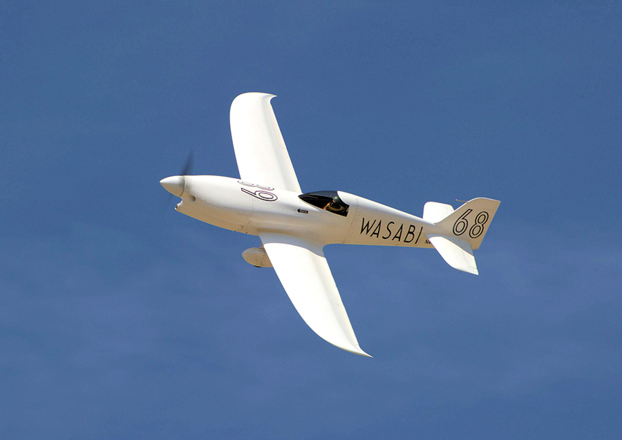
Photo courtesy Naomi West)
Recently though, a greater number of bespoke Formula 1 planes are showing up at Reno—Steve Senegal’s Endeavor, Brian Reberry’s September Fate, and Elliot Seguin’s Wasabi, to name a few. The sinuous, all-composite construction of these airframes has lowered the drag count a few ticks more, and Cassutt drivers have been forced to become more creative to keep up.
One of the most effective airframe mods is to update the wing and tail feathers. This typically means fitting a composite, high-aspect-ratio planform utilizing a natural laminar-flow (NLF) airfoil. Properly built, carbon or glass wings can offer strength/weight advantages over wood and have higher profile accuracy. The high aspect ratio reduces induced drag in the turns, and the NLF airfoils generate significantly less drag than their NACA precursors (see “Why Elliptical?” below).
This article outlines the design and construction of Iscold’s wing, and highlights the technology and techniques that allowed what Catto has called “probably the most accurate Formula 1 wing ever” to be created in such a short amount of time. The wing was designed and built by Iscold with help from the author over four weeks during the summer of 2014. This month in Part 1, we’ll look at the design of the wing and use of a CNC (computer numerically controlled) milling machine to produce molds and ribs. In Part 2, we’ll take a photo tour of the assembly of the wing itself.
While one of our goals at KITPLANES is that you should be able to build something after reading an article, I’ll admit that you’re probably not going to be able to pop out a composite wing after reading this. Rather, the goal here is to introduce readers to techniques they might not normally encounter and demystify composites a bit. Although I realize many builders consider epoxy and pinholes to be the bane of their homebuilding existence, I encourage you to be open to the possibilities composites offer. I love working in plastic as much as I love working in metal—they each have their unique character, skill-set requirements, and aesthetic rewards. So rather than a source of exact techniques, consider this article a source of ideas and inspiration.
Computer Aided Design
Iscold utilized a racecourse modeling and design optimization program similar to that used for his work as chief race aerodynamicist for Paul Bonhomme’s Red Bull Air Race team. The course was altered to reflect the Reno course, i.e., a race track with a pair of straightaways between near-constant-radius turns at each end. Approximate density altitude and the client’s aircraft weight were known parameters, but not horsepower, so lower and upper power figures of 100 hp and 160 hp were used. The computer model gave lower and upper course speeds of 193 mph and 238 mph, similar to that seen in Cassutt racers Scarlet Screamer and Miss USA, respectively. This simulation backtesting confirmed that Iscold’s model was generally accurate and therefore gave him confidence in using the model to design the client’s wing.
The next step was to determine the range of lift coefficients (CL) that the wing would encounter. The lift coefficient dictates how much lift a wing will produce at a given angle of attack. It is particularly important to consider CLwhen designing a wing with a laminar flow airfoil, as these airfoils exhibit a phenomenon known as a laminar drag bucket—a narrow range of angles of attack where the drag drops significantly (see Figure 1). If the wing manages to operate within the upper and lower angles of attack that define the edges of the low-drag bucket during the race, it will be significantly faster. Operate beyond those angles and speed suffers drastically.
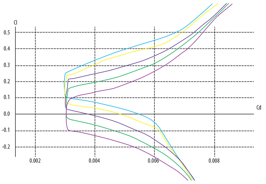
Figure 1. Simulated lift/drag polar of modified NLF 0414 at various camber settings. Note that theoretical CD is relatively constant at approximately 0.003 over a CL, followed by a space and full-height triangle symbol CL? of 0.2. At off-design CL, drag increases exponentially. It is important to design the wing to stay at the bottom (i.e., far left) of the bucket over the course of the race in order to maximize speed. (Graphic courtesy Paulo Iscold)
Iscold’s simulation indicated that both planes would see a CL of approximately 0.45 in the turns and 0.10-0.14 in the straightaway. The optimal NLF airfoil then should be able to operate from a low of approximately 0.10 CL to a high of 0.45 CLwhile remaining in its drag bucket.
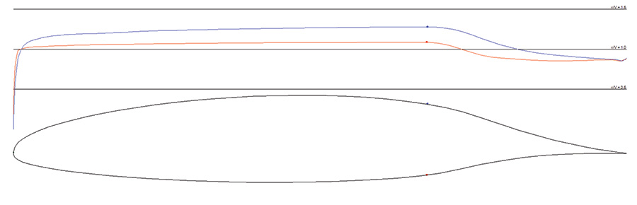
Figure 2. Unmodified NLF 0414 profile with velocity distribution, plotted with AeroFoil V3.2. (Courtesy Donald Reid—aerofoilengineering.com)
The starting point for the airfoil was the NLF 0414, a popular high- speed laminar airfoil (see Figure 2). This airfoil has a drag bucket optimized for a lift coefficient of 0.4, so the range of the bucket needed to be adjusted downward (note the median CLof .17-.21 in the upper right of the CL? simulation shown in Figure 3). This was achieved by simply reducing the camber of the airfoil. In addition, Iscold likes to modify the leading edge of NLF airfoils from a radius to a spiral arc, as his studies indicate this softens the stall.
Dr. Iscold studies a finite element analysis (FEA) of the wing to ensure that loads are safely distributed. FEA essentially breaks a large, complex structure (or problem) into many small elements which are more easily analyzed.
Iscold then looked at the planform of the wing and lift distribution during the race—in essence, how CLwould vary spanwise over the wing. Elliptical planforms are ideal for minimizing induced drag (see sidebar), and Iscold’s design approaches the ideal while keeping sufficient wing area at the tips to avoid tip stalls during landing. This planform necessitated further tweaking of the airfoil to ensure that all parts of the wing were operating in the drag bucket during as much of the race as possible. Since the racers spend longer in the straightaways (lower CL) than in the turns (higher CL), a lower CLdrag bucket was given preference over a higher CLbucket when it was impossible for the bucket to span the entire range of lift coefficients seen during the race. Finally, the wing aspect ratio was optimized, yielding an AR of 6.9 and wingspan of 21 feet, 4 inches. Iscold’s computer model indicated that with a 160-hp engine, the client’s airplane should theoretically achieve a lap speed of approximately 244 mph.

Figure 3. CL ? simulation using upper and lower power limits. CL peaks in the turns where the wing must generate large amounts of lift (to counter centrifugal force) and drops in the straightaway. (Graphic courtesy Paulo Iscold)
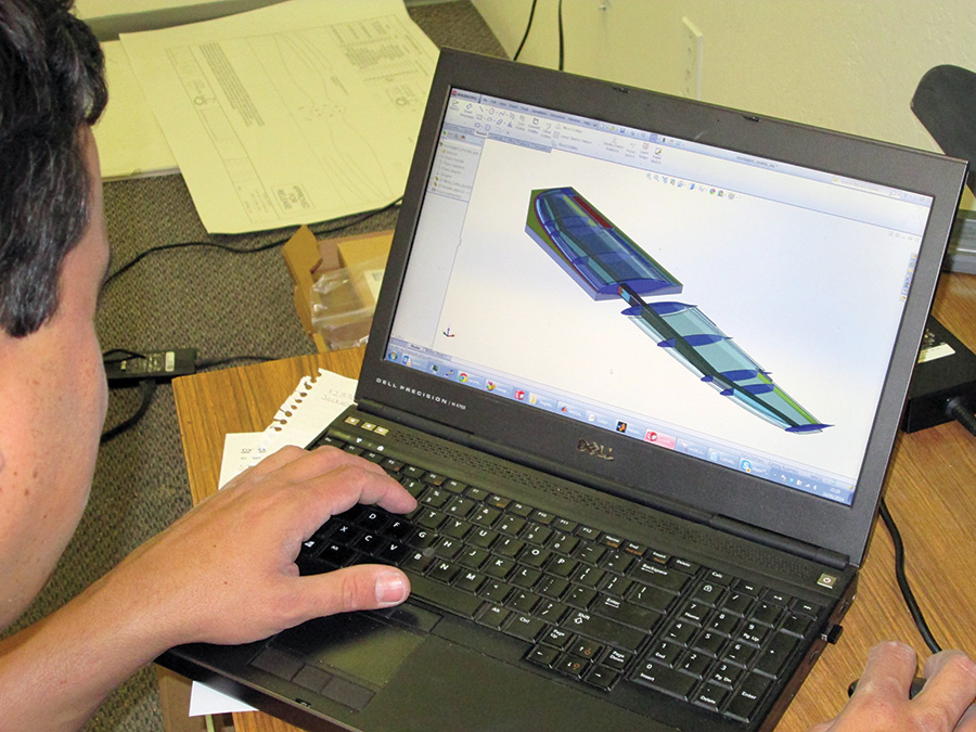
Once Iscold had the aerodynamic design of the wing pinned down, he then performed a finite element analysis (FEA) of a SolidWorks CAD model to ensure the wing was structurally sound (the wing is designed for a load limit of 6 G and ultimate load of 10.35 G). Once the SolidWorks model was complete, the file was processed with CAM software and uploaded to Catto’s CNC.
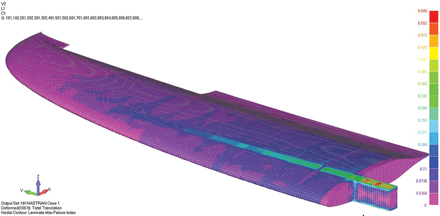
Computer model of torsional stiffness. The wing experiences less than 1 degree of aeroelastic twist at 6.7 G and 280 mph. (Graphic courtesy Paulo Iscold)
Fun with CNC
Catto Propellers has two 5×10-foot CNC machines—perfect for machining wing molds! Although Iscold uses eucalyptus MDF (medium density fiberboard, a wood product similar to particle board) for his one-off CNC molds in Brazil, North American pine-based MDF is less suitable for mold making. The machined surface is slightly fuzzy, higher porosity can make vacuum bagging problematic, and it is more susceptible to warping from humidity changes. For small parts though these issues are surmountable, and pine MDF was used for the aileron molds.
Given Catto’s intention to offer these wings to other Cassutt drivers, the project invested in tooling foam for the wings (each 48x96x4-inch sheet cost approximately $1500). While the pink or blue extruded polystyrene foam insulation board that homebuilders sometimes use for composite cores weighs about 2 pounds per cubic foot, tooling foam is much denser—from 3-50 pounds per cubic foot. Ten-pounds-per-cubic-foot medium-weight foam was chosen as a good balance between durability (although quite dense, it still dings more easily than say 20-pound foam) and cost (higher density foams are more expensive, and large molds can be extremely heavy). Tooling foam machines quickly, with excellent surface quality, but requires more care in handling and storage, as well as different layup techniques compared to a fiberglass mold.
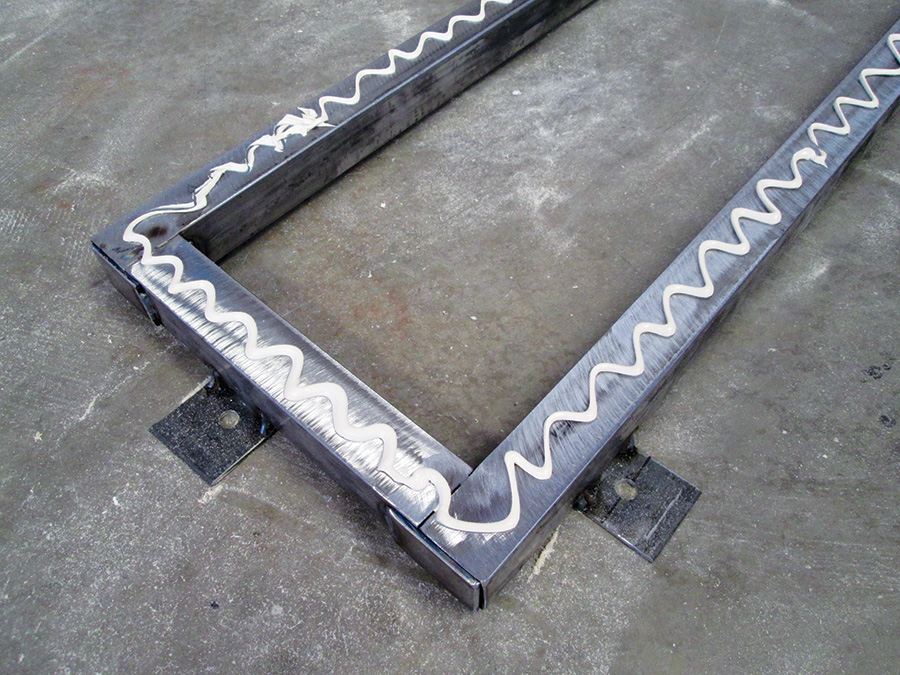
Mold frame for the horizontal stabilizer with CNC-bed locator tabs. Construction adhesive has just been applied for application of the particle board base.
The first step in machining the molds was to build a frame to support the 48x96x4-inch foam during CNC machining. A frame slightly larger than the foam sheet was welded from mild steel, with tabs to allow the frame to be bolted to the CNC bed. Particle board was then bonded to this frame with construction adhesive, and the tooling foam (or MDF, in the case of the ailerons) bonded to the particle board base. The steel CNC mounting frame thus also serves as a permanent support structure for the mold.
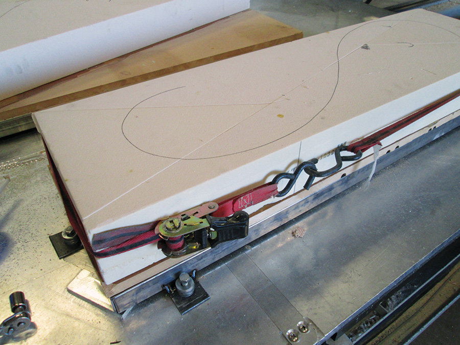
Frame bolted to CNC. Due to the high cost of tooling foam, the cutoffs from the wing molds were reassembled into a rectangle for the horizontal stabilizer mold. A ratchet strap holds the foam tight while the epoxy bonding it to the base board cures.
In addition to machining the molds, the CNC was also used to machine the foam core of the spar (from 2-pounds-per-cubic-foot blue foam) and ribs. For the ribs and some ancillary parts, two 3×4-foot panels of carbon-Divinycell-carbon were vacuum bagged, cured, and then machined to shape (Divinycell is a closed-cell, high-density foam commonly used as a core material in composite sandwich construction). Quarter-inch Divinycell was also CNC cut to shape and edge-beveled for the wingskin core.

Overhead view of the wing mold being CNC’d. Here the CNC is slowly making its final cut after making a faster initial rough cut (the elliptical shape of the wing can be made out at this point). The steel frame, mounting tabs, and particle board bed can all be seen in this picture. Although the frame is quite stiff, the wingskins were actually laid up on the CNC table to ensure maximum straightness. To the degree possible, most work using the CNCs was performed after hours when the table would have been otherwise idle.
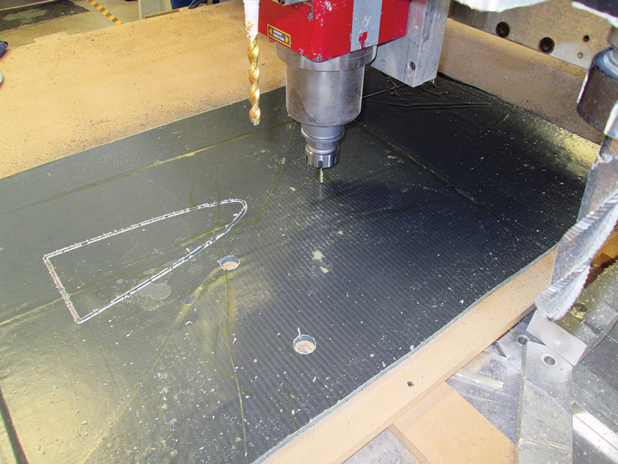
Ribs are CNC’d from a panel of carbon-Divinycell-carbon sandwich. The panel is lightly bonded with contact cement to a sacrificial bed of MDF, which is itself temporarily clamped to the CNC table during the operation. After machining, parts are easily removed from the MDF with a drywall spatula. For small parts like this, a small .125-inch toolhead is used.
Machining time was about 40 hours for the wing molds (10 hours each for upper right, upper left, lower right, and lower left molds), 8 hours for the horizontal stabilizer and elevator, and 8 hours for the aileron molds. Once cut, the molds required no further preparation before layup due to the rapid prototyping method used, which we will cover in Part 2 of this article.
Preparing the molds, spar and internals took two people approximately 10 days. Once these preparations were finished, we were free to begin fabrication and assembly of the wing itself, which required approximately 20 more (long) days of work. Because progress was rapid and visible, motivation remained high. Although there is obviously a large investment of time and money required to acquire the skills and tools to design and manufacture with CNC, once they are in place this kind of rapid prototyping makes for exciting, fast-paced projects. Join us next month for a step-by-step photo-journal of the wing assembly.
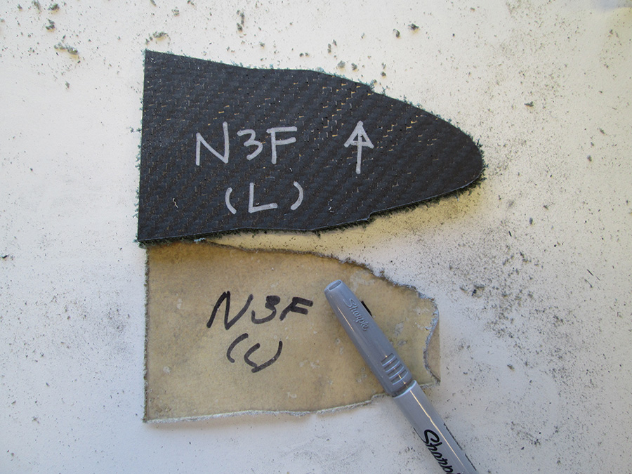
Nose rib (above) and aileron rib (below). Part number and orientation are written on the rib upon removal from the CNC. The peel ply is removed shortly before actual assembly, at which time the part number is transferred to the carbon face using a silver Sharpie. (Peel ply is a sacrificial layer of synthetic cloth that tears away from the surface of a composite part, leaving a slightly rough surface that is advantageous for bonding). CNC’d parts straight off the table look rather fuzzy like the nose rib above, but clean up nicely like the aileron rib below once the peel ply is removed and edges lightly sanded.


The last component to be CNC’d is the wing core. As with the carbon sandwich panel, quarter-inch Divinycell is lightly bonded with 3M Super 77 to the sacrificial MDF bed. Once the edges are cut and beveled, the Divinycell is carefully pried loose with a drywall spatula. The wing cores are then rolled with a porcupine roller to ensure a good bond to the carbon skin.

Elliptical wings, like those on the Spitfire, are often cited as being most efficient (in truth, wind tunnel studies show that crescent-shaped wingtips, like those on the Nemesis NXT, are slightly more efficient. For more, see C. P. van Dam’s paper “Induced-Drag Characteristics of Crescent-Moon-Shaped Wings” in the Journal of Aircraft). This is due to the fact that when there is a pressure difference above and below a wing (this difference being what gives a wing lift), the high-pressure air on the bottom will roll over at the tips to equalize with the lower pressure on the top (and thereby create vortices).
Intuitive but incorrect conception of lift distribution, in which lift is proportional to wing chord. (Graphic courtesy Olivier Cleynen/Creative Commons)
However, if we bring the pressure difference to zero at the tip (by tapering the wing area to zero via the elliptical planform shape), the vortex is minimized (though not eliminated). We can also bring the pressure difference to zero by using aerodynamic washout—angling the wingtip angle of attack down so that at a particular angle of attack, the wingtip is generating neither positive nor negative lift—the upper and lower surfaces are at equal pressure, and again vortices are minimized. The problem with washout is that it only works at a single angle of attack. As soon as you change that angle, your induced drag will increase. A wing with an elliptical planform doesn’t face this problem since it achieves zero tip lift via wing shape, and that shape is constant regardless of angle of attack.
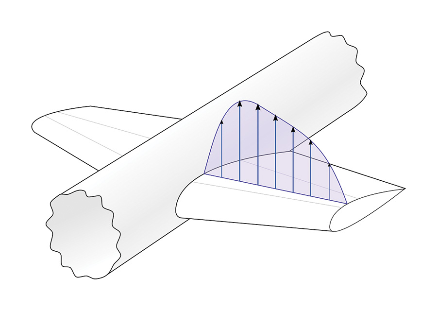
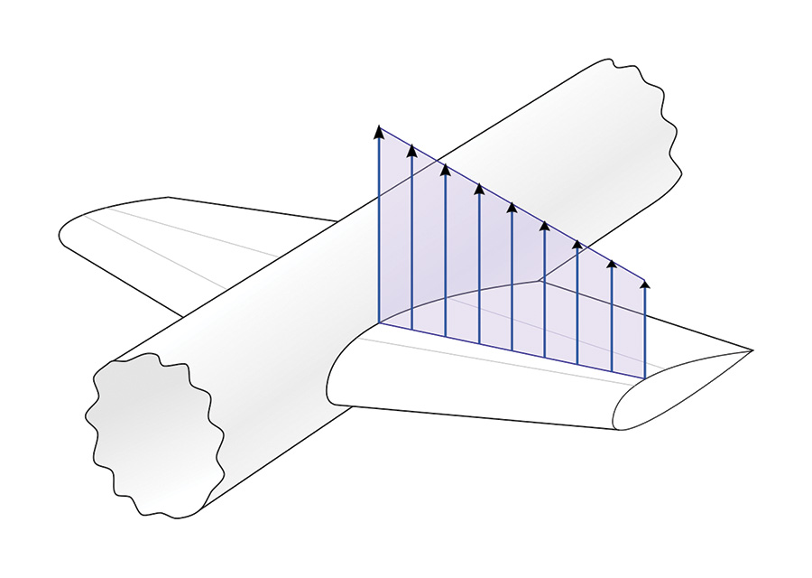
A more accurate illustration of elliptical lift distribution, showing lift tapering to zero at wingtips irrespective of the tip chord. At the root, the lift distribution does not typically go to zero but in fact bridges across the fuselage. (Graphic courtesy Olivier Cleynen/Creative Commons)
While it might seem that a straight taper to a sharp tip (i.e., a delta planform) would also achieve the goal of zero lift at the tip, pressure along the wing tapers naturally in an elliptical fashion, and so matching the shape of the wing (elliptical) with the pressure taper (elliptical) means that each section of the wing is generating exactly as much lift as it needs to. Since induced drag grows exponentially with lift, pylon racers need to pay special attention to this parameter since they generate huge amounts of lift when rounding pylons. For a fascinating analysis of aspect ratio as it pertains to F1 racing, see Stan Hall’s classic article “High Aspect Ratio Wings for Formula One Racers” in the September 1988 issue of Sport Aviation.
—E.S.


Great article. Congratulations and many thanks for sharing