I caught up with my A&P friend Randy Richmond at his hangar, where he was wrestling with a beautifully polished bare-aluminum RV-3. The wings and cowling were off, and he was hoisting the engine from the airframe’s nose. Now I normally find Randy and his helper Tony conducting annuals or some other spot maintenance on the hangar’s temporary tenants, usually Experimentals, along with the occasional V-tail Bonanza or Mooney. But this job looked a little more extensive.

Can you spot the cracks after years of abuse from loose lower engine bolts?
Before I asked if he and Tony wanted to hit Reno Red’s for their Monday sirloin lunch special, I noticed that Randy wasn’t merely block-lifting the engine from its mounts. The engine was in fact still bolted to the engine mount, but the mount was unbolted from the firewall and frame, plus the prop was still on the engine. Intrigued, I had to ask what maintenance task he was tackling.
“Ugh, it’s these danged RV-3 lower airframe engine mount bolts…they’re just as loose as can be,” he explained. “I can shake the whole engine about an eighth of an inch, mount and all!”
This surprised me, particularly as nice as the airplane looked. It wasn’t new…in fact it was probably the better part of 20 years old…but it looked well built, had been hand-polished (a lot!), and, well…loose engine bolts? How?
Randy gave me a quick lesson on early Van’s kit aircraft designs. It seems that RV taildragger models, with the maingear mounted to the engine frame, require the builder to fabricate the airframe hard points that come together where the engine frame bolts to the airframe. Truly, no two airplanes are alike because none of each aircraft’s hand-fabricated parts are ever identical. For that matter, the builder had to figure out the build order on their own, unlike my quickbuild A-model kit, which came with a more useful set of step-by-step directions.
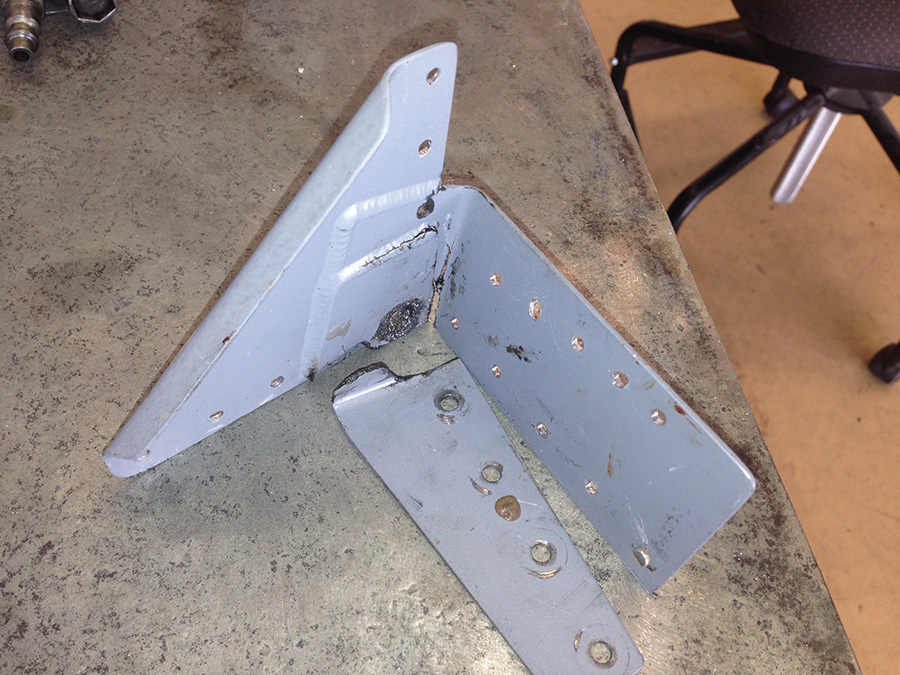
Here’s the same part after being removed from the airframe.
This takes us to the lower engine-mount/firewall/frame bolts. Randy went on: “Creating that hard bracket fastening point on the airframe involves mating several solid structural pieces, then drilling through them and the firewall to create the bolt hole for the engine mount. That’s not a problem unless, after drilling the bolt hole through the assembly, the builder fails to separate the pieces and remove the metal shavings. Apparently, this aircraft’s original builder did not take the time to remove those shavings, so they remained sandwiched between the solid hard point members. Over the years, many hundreds of positive and negative G load cycles smashing those shavings created stress points in the airframe mount pieces, which work-hardened and developed cracks.” Randy said he sees this all the time.
I have to admit, for a moment, I felt this sort of panicky twitch. I mean, what he described sounded like the sort of thing an amateur would do. But, wait, I resemble that remark…I’m an amateur builder! Over the last 1200+ hours of building, what unforeseen risks have I unknowingly introduced to my RV-7A?

Here’s the same mount once it was repaired and replaced.
New Designs, Problems, Solutions, and Risks
When designing a new aircraft, designers must blend structures and systems in a manner that’s effective, efficient, lightweight, and safe. Designers look for conflicts: Will this wiring harness get too close to a heat source? Will that load point spread evenly across the airframe, or will it fail if given enough load cycles? Furthermore, in the case of an Experimental design, has the designer made the airplane “buildable” by the amateur kit builder?
Once the designer has carefully examined the design for hazards, if they exist, he must engineer safety features to prevent (or mitigate) the hazard, and also warn the pilot should the unthinkable happen. The engineer omits such safety features only if he has extremely high confidence that the hazard won’t ever happen. In a helmet bag, that’s risk management in aircraft design.
The lower mounting bracket on the left side of the fuselage was damaged even more than the right bracket shown on the previous page.
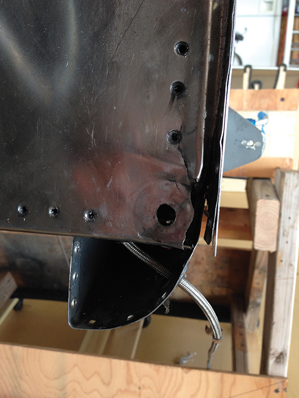
With the bracket almost completely destroyed, additional damage occurred to the firewall.
The F-22 Raptor is a spectacular aircraft design. It features a 270-volt DC electrical system powered by two 65-kilowatt generators, and a redundant 4000 psi hydraulic system. These two systems reside very close to one another in what’s called the aircraft mounted accessory drive (AMAD) bay. The designers did a great job securing those high-voltage electrical wires, keeping them away from the steel-braided hydraulic lines so that they’ll never contact each other and chafe…so good that they reasoned there was zero risk of fire. Thus, the F-22 design omits any fire warning or extinguishing capability for AMAD fires.
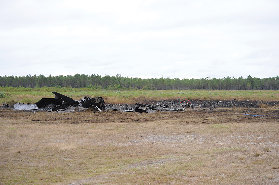
F-22 Raptor lost to a fire in the aircraft mounted accessory drive (AMAD) bay. The pilot successfully ejected. (Photo courtesy USAF Public Affairs)
In 2012, an F-22 on a training mission experienced an AMAD fire. Somehow, one of those 270-volt positive feed wires got close enough to a braided hydraulic hose that it chafed and arced, perforating the hydraulic line. This knocked the generator offline, while the pin hole in the hydraulic line filled the AMAD bay with highly flammable hydraulic mist. When the pilot tried to reengage the generator, the ensuing electrical arcs ignited the misting hydraulic fluid and ignited the AMAD bay fire. This triggered a series of cascading electrical and hydraulic
systems failures. Without hydraulic power, the Raptor’s flight controls became inop, and the pilot successfully ejected. Last I heard, the manufacturer was looking at even better standoff clamps for those wires and hoses, and mods to introduce fire warning and suppression systems in the AMAD bays.
I have no doubt that the designers completed a thorough and conscientious risk assessment on the AMAD bay, I really do. Designers are conservative by nature, and lean toward the proverbial safe side when it comes to these sort of hazards and safety systems. I believe they were completely confident that they had managed the fire hazard with their design, and yet the fire still happened.
As I build my RV-7A, I have repeatedly asked myself, “How sure am I that this EGT wire won’t rub against that oil line?” For only the slightest doubt, I have called Aircraft Spruce for more Adel clamps.
The Design Looked Good, But…
In 2012, a builder/pilot launched his Fighter Escort Wings (FEW) P-51 replica for a Phase I test flight. During cruise, he suddenly experienced electrical problems resulting in insufficient voltage to maintain engine ops using either the primary or secondary battery circuits. He lost all engine power and performed a wheels-up landing on a gravel road. He walked away, but his Mustang was heavily damaged.
The replica fighter was powered by a non-certificated auto engine with computer-controlled electronic ignition and high-pressure fuel pumps. That’s not a problem, but the two 12-volt batteries wired in parallel to provide voltage to the main bus for engine systems? Big problem.
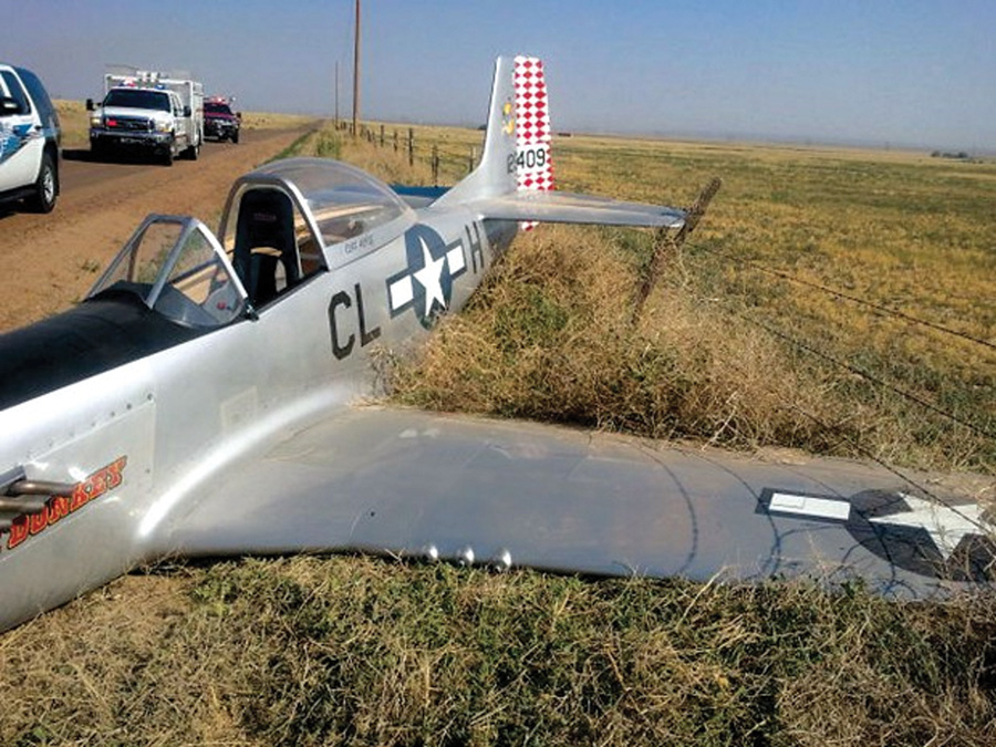
Fighter Escort Wings P-51 replica after losing electrical power on a Phase 1 flight. The pilot walked away. (Photo courtesy Pueblo County Sheriff’s Office)
According to the NTSB report, the primary battery had developed an internal short and couldn’t take a charge. Because the two batteries were in parallel and weren’t isolated from each other, the first battery’s internal short drained both batteries. The NTSB cited the inadequate electrical system design as causal.
Now, rigging batteries in parallel is not uncommon in the Experimental aircraft world; however, when done properly, the design must allow the pilot to disconnect the batteries from each other to prevent dual-battery depletion. This FEW Mustang’s battery connections didn’t include a disconnect feature.
I admit I wouldn’t have thought of that risk because I’m not that smart on electrics yet (I’m an amateur, remember?). But I do know that the FEW Mustang’s original design called for a single battery, even though many builders install a second battery to reduce risk. However, in addressing one risk, this Mustang succumbed to another.
Managing the Unseen Risk
So how do we catch these unforeseen risks? Did we introduce a new risk? How do we eliminate it, or at least reduce it to acceptable levels? For that matter, is it still legal? When we exercise our Experimental aircraft freedom to deviate from the plans and tailor the aircraft for our own needs or desires, we’ve got to run the new design across the experts.
Our EAA chapters are loaded with experts, many of them “repeat offenders” who might have seen (or even applied) these modifications before, or heard of the results. Let them examine your plan and give you feedback.
Better yet, take your ideas to the mother ship: Consult the kit manufacturer’s designers and discuss it. For example, I wanted to install my top forward fuselage skin with flush-head screws rather than rivets, which would allow me to remove the skin for access to the upper forward components residing between the instrument panel and firewall. This would entail platenuts on the ribs and bulkheads, and tapping screw holes in the solid aluminum angle longerons.
The Van’s engineers waved me off, for reasons I hadn’t considered. That skin is part of the aircraft’s stressed skin forward structure. The aircraft’s structural engineering design allows for the #3 rivet holes in the longerons, but not for enlarged or tapped holes. They had never conducted an engineering assessment on the aircraft’s forward structure to account for all those additional rivet holes, the screws, or the sort of “damage” (their word) caused by tapping threads into the longerons. I decided this was a bit too far into the unknown, so I dutifully followed the instructions and riveted the forward skin into place.
As for the RV-3 in Randy’s hangar, I asked him how I could keep something similar from happening to my RV-7A? “Simple,” he said.
“First, build according to the plans as much as possible. Next, use proper building techniques and have your work examined often…don’t be proud. As for the engine mounts, they’re going to loosen up, so check them every time you change the oil; after several tightenings, they’ll settle in. Finally, every time you inspect the airplane, put a wrench on everything, and I mean every nut and bolt.”
Got it, Randy, thanks. So, are we hitting Reno Red’s for lunch today?
Note: All references to actual crashes are based on official final publicly-released NTSB and Air Force Accident Investigation Board reports of the accidents, and are intended to draw applicable aviation safety lessons from details, analysis, and conclusions contained in those reports. It is not our intent to deliberate the causes, judge or reach any definitive conclusions about the ability or capacity of any person, living or dead, or any aircraft or accessory.

![]()
Sid “Scroll” Mayeux has over 25 years of experience in aviation training, safety, and risk management in the military, civilian, airline, and general aviation sectors. He currently trains Boeing 777 pilots, and he is building a Van’s RV-7A.


