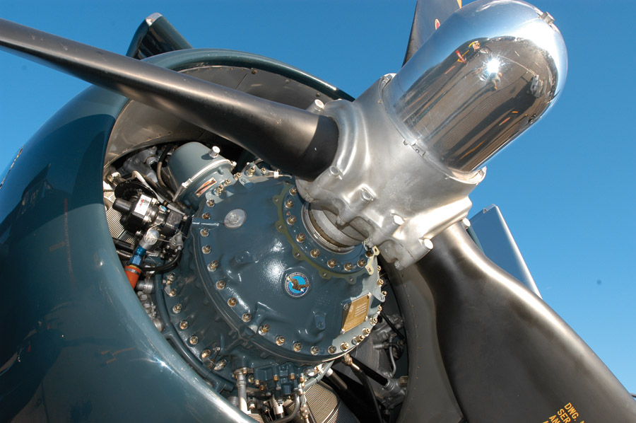
Now there’s a gearbox. Imposingly large, the planetary reduction on the front of this R-2800 is the result of painstaking development by Pratt & Whitney. Input from vibration specialist Den Hartog of Harvard (and later MIT) plus endless rounds of crankshaft failures in the dyno cell eventually resulted in a reliable engine-gearbox-propeller combination at well over 2000 hp. Don’t forget the metal propellers weigh hundreds of pounds, and the whole lot was reliable through combat aerobatics.
Great debates are born when both sides of an argument have at least one gear leg to stand on, such as if a 180-mph homebuilt should use a fixed-pitch or constant-speed propeller. And right there with that classic is propeller speed reduction—it has drawn as many of the self-anointed into computer-aided hangar flying sessions as anything.
Ironically, as amateur builders gear reduction is not much of a practical concern. You either fit a big Continental or Lycoming without a gearbox or you’re set on a smaller Rotax, auto engine conversion, or compact ultralight engine that does use a propeller speed reduction unit. Either way the mechanicals are fairly pre-determined.
That said, there is much to know regarding slowing the propeller down, much of which may directly involve your corpus or wallet’s well-being in rather dramatic fashion. The stakes rarely get higher, or the technical devils seemingly more elusive than dealing with anything other than the most professionally developed PSRUs.
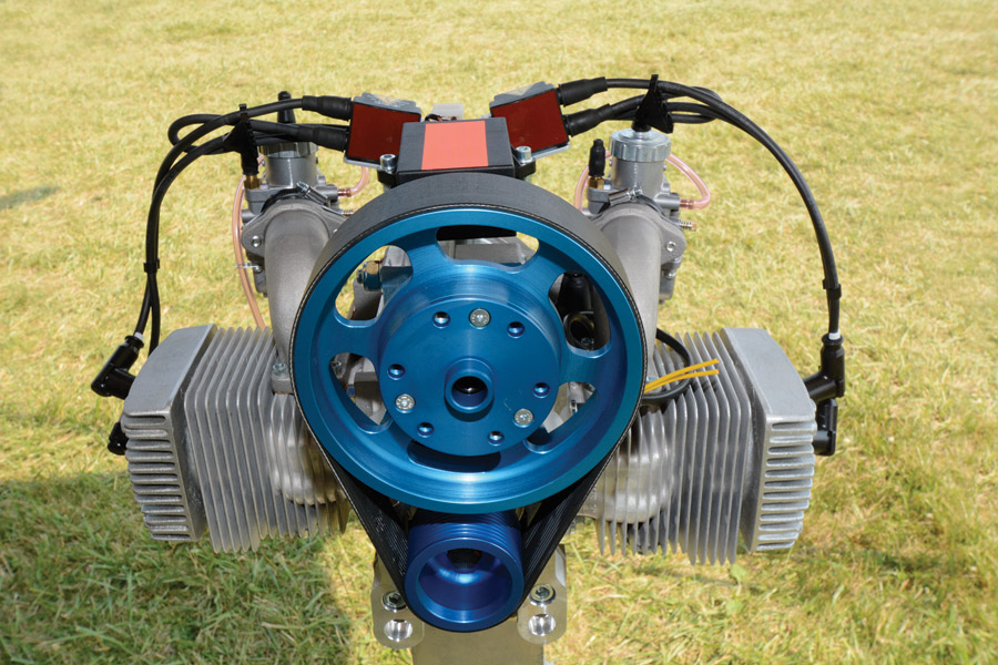
Small-displacement engines naturally run at relatively high rpm to make power and therefore require propeller speed reduction gearing. Luckily, the modest power involved can be handled by simple belt-drive reduction units. A wide, ribbed belt and good belt wrap around the pulleys mean no belt tensioner is used.
To Slow Or Not To Slow
The whole point of a PSRU is to slow the propeller relative to the engine. This is because propellers gain aerodynamic efficiency with reduced rpm, as the learned Mr. Wainfan has recently detailed in his Wind Tunnel column [KITPLANES, June 2016]. Piston engines, on the other hand, gain horsepower and sometimes efficiency with a bit of rpm. This is especially true if the engine’s displacement, overall size, and weight are being kept in check as they are in aircraft, as compared to a locomotive or ship engine, let’s say.
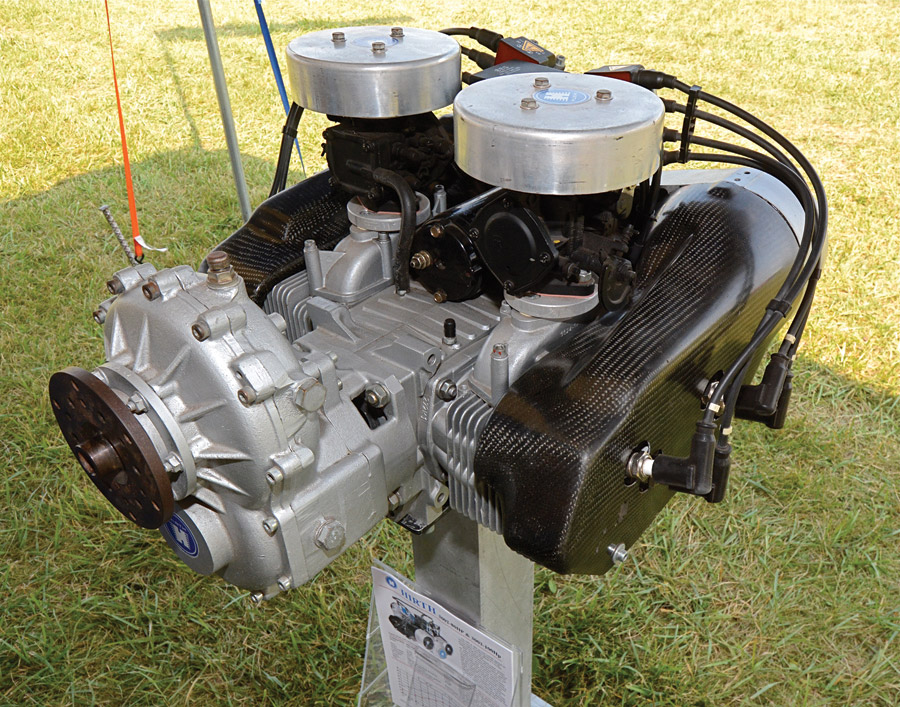
Most powered parachute, ultralight, and other micro-aviation engines use belt drive reduction, but as such engines grow in size, cylinders, and power, they can sprout geared drives. The Hirth 80-hp 3002 and 100-hp 3003 4-cylinder, 2-stroke opposed family seen here is a good example.
In short, within limits, a fast engine and a slow prop makes everyone happy.
Of course, turning the propeller more slowly than the engine requires some sort of mechanical ratio between the two. This is either a gearbox or belt drive, both of which introduce increased cost, weight and, above all, complexity and a surprisingly large number of not immediately apparent but significant mechanical considerations. Bluntly put, PSRUs are trouble and need be designed and developed with care by people who know what they’re doing and have the resources to fully vet their creations.
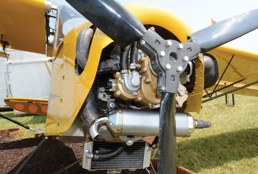
Polini, an Italian motorbike and ultralight engine builder, uses a helical-gear PSRU with centrifugal clutch on their THOR 250 Dual Spark engine. The single-cylinder 2-stroke looks a lot like a Honda CR bike engine sitting side-saddle in the Belite’s engine compartment (carburetor to left and exhaust to the right) and is rated at 36.5 hp at 7500 rpm. A 2.8:1 gear reduction turns the 54-inch Powerfin 3-blade just under a familiar 2700 rpm at takeoff and about 2300 rpm at a 6500 rpm cruise. The centrifugal clutch means the Powerfin gets a freewheeling pass at what must be a somewhat jerky idle; the gear drive also provides convenient water pump and starter motor real estate.
Naturally, prop speed reduction is sometimes a necessity, trouble or not. Back when Pratt & Whitney, Allison, and the rest of them were making 2000 hp with pistons, there was no question such engines would incorporate a gearbox. Trying to harness that much horsepower to the atmosphere demanded huge props, which absolutely had to turn slowly to avoid excessive tip speed. Even with geared engines the still large propeller diameters posed real issues for designers when it came to landing gear; witness the inverted gull-winged Corsair or towering Constellation airliner.
Similarly, ultralight powertrains use tiny engines dependent on high rpm to make power. The only way to get workable thrust from such engines is to gear down the propeller, and even then many such props are still on the fast, noisy end of things.
Likewise, automotive engines are bred to loaf at surprisingly low power at low or medium rpm and make rare bursts of meaningful power at high rpm. When converting them to constant high output, there’s typically no choice but to turn up the rpm to make power and fit a gearbox to reduce propeller rpm to more efficient levels.
You may have noticed Continental and Lycoming aviation engines are somewhere in between our example engines in size and rpm. That’s no accident; the 2500- to 2700-rpm direct-drive aviation engine turn is a compromise fast enough to make some power and slow enough for efficient propeller diameters.
It’s certainly not because the engines don’t appreciate being turned faster. Nearly all traditional general aviation engines are tuned to run at their torque peak (point of best fuel economy) during cruise, which is only a couple hundred rpm less than their maximum power rating at takeoff. From a tuning perspective, reaching their native maximum horsepower output would require an extra 1000 rpm or more. Furthermore, there are no piston speed or other mechanical reasons most of these engines couldn’t safely turn another 1000 rpm. But in direct-drive guise they don’t, only because propeller efficiency and (especially from a safety standpoint) propeller mechanical integrity don’t allow it.
In fact, when Continental and Lycoming did add gear reduction units to a few of their engines in the 1950s and ’60s, the engines needed no major changes to turn significantly higher rpm. For example, the GO-480 Lycomings found in light twins turn 3600 rpm at takeoff while the props are at just 2300 rpm. At typical cruise settings the engines might turn 2500 rpm and the props just 1600 rpm, thanks to a 0.642:1 gear reduction ratio.
That extra engine rpm really helps make power, too. The GO-480 in a Twin Bonanza is rated at 285 hp. Considering a GO-480 uses six cylinders from the 4-cylinder O-320, we can easily extrapolate a hypothetical non-geared “O-480” would have made just 225 hp. That’s 60 missing horsepower, a 30 percent loss, due to the rpm limitation! Furthermore, the higher-rpm engine is receptive to the usual power-building tricks. The supercharged GSO-480s are rated at a healthy 340 hp, for example.
Let’s not forget the power these geared engines generate is more efficiently turned into thrust by slower-turning props. PSRUs may be trouble, but they perform.
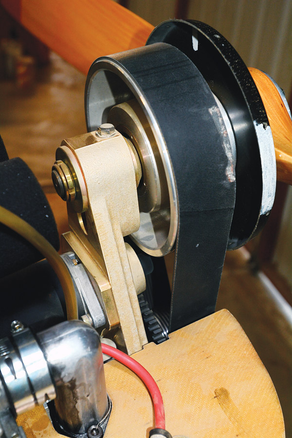
Looking at the backside of a small-plane belt drive shows how the modest forces at play in diminutive engine and prop combinations allow basic engineering to get by. Physical strength to withstand thrust loads is supplied by mass and not triangulation here; harmonic issues are no doubt similarly handled. The tiny engine and wood prop have enough mass and native damping to live a reasonable life, given the small torsionals generated. Also, this open-air drive clearly illustrates how belt drives aren’t conducive to hydraulically operated constant-speed props; if a twisty prop is needed, electricity is the usual solution.
PSRU Designs
There are two basic categories of prop speed reducers: belt and gear. Belt-driven reduction units are simple, relatively lightweight, and don’t pose many design difficulties. Gear-drive units are either straightforward spur gear arrangements where one gear drives another, or more involved planetary arrangements where many gears are arranged in a sun-and-planet layout to drive the propeller.
Belt drives typically consist of a grooved or toothed composite belt and a pair of sprockets, one on the crankshaft and another at the propeller, and perhaps a belt tensioning pulley. They are refreshingly simple, typically reliable, and easy to design units. They tend to be quiet—though not always—and while they offset the engine’s crankshaft centerline from the propeller’s, this isn’t much of an issue, or can even be an advantage, with the small engines belt drives are typically fitted to.
Speed Reduction Conditions and Concerns
Major downside to the belt drive is its limited torque capacity. Higher-powered engines literally strip belt and sprockets, so by V-8 power levels a belt drive is losing its appeal. If anything, the latest trend is toward gear drives on smaller and smaller engines.
It’s possible to use a linked metal belt, but this often results in greater weight, not that much more strength, and complications of the inertial weight of the belt trying to stand off from the sprockets at higher rpm.
It’s worth noting the one supposed advantage for belts—isolating the propeller from destructive engine vibration—is of little utility. That’s because the high-strength fibers in belts—strands of Kevlar, steel, and so on—are sufficiently inelastic they transmit excitations with little damping.
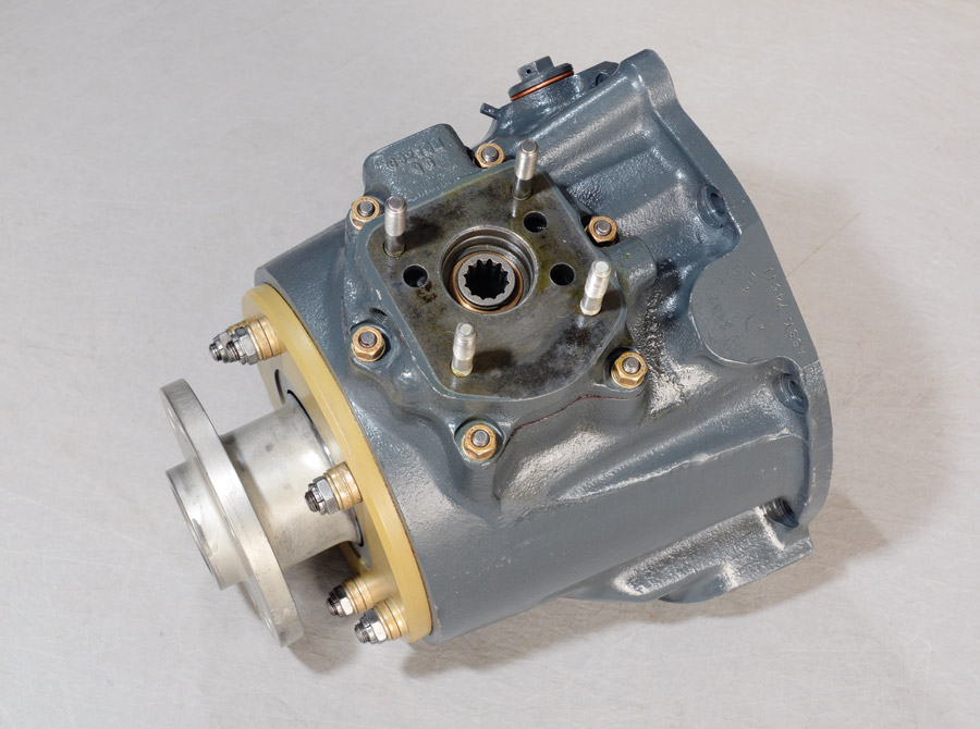
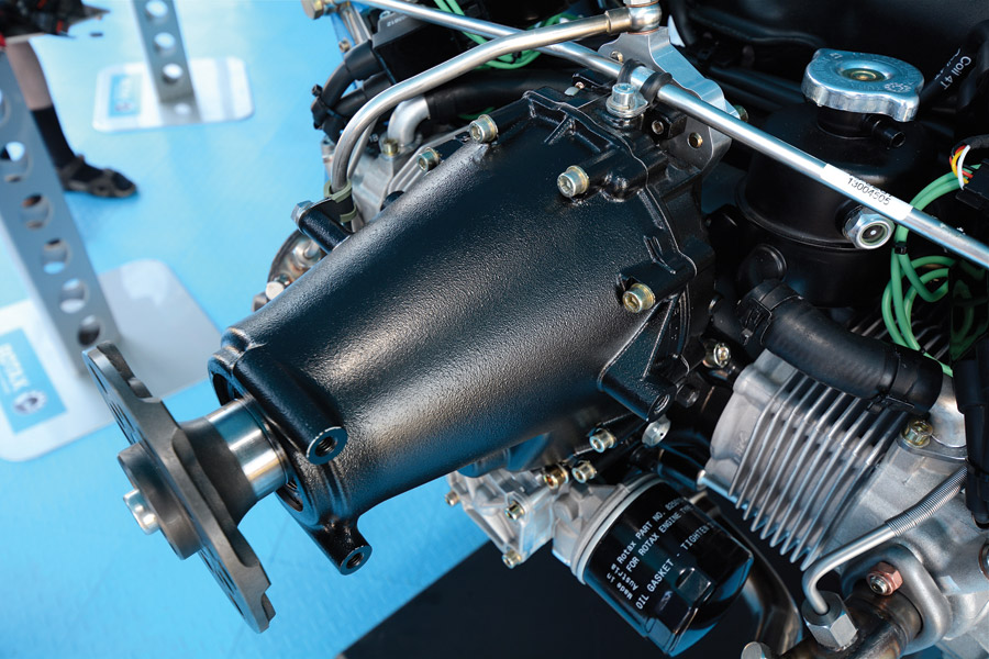
Bob Hume was kind enough to break out for the camera his spare gearbox for the GO-480 Lycomings on his Twin Bonanza. In the outside view the prop flange at left and governor drive on top are readily visible, along with the overall beefy construction (it’s heavy as sin).
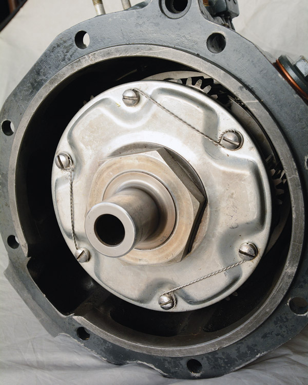
Peering inside in the second photo, the shiny cover over the planetary carrier is mainly what’s visible. A close look shows two of the six planet gears just poking their teeth out. Also, the gearbox is obviously open to the engine crankcase and shares its oil supply. These gearboxes are reliable, as long as they aren’t coasted or driven by the prop; they rattle like castanets during engine start and shut-down.
We’ll also note belt drives keep the engine and propeller rotating in the same direction, so reverse rotation props are not needed.
And then there are gear-drive reduction units. The big deal with metal-to-metal gears between the engine and propeller is engine torsional vibrations are not only amplified by the gear ratio but are energetically transferred to the prop. These vibrations originate with the crankshaft, which does not rotate smoothly and is jerked back and forth by the cylinder’s power strokes; balance characteristics play a part in this as well. Certain engine speeds result in the torsional forces harmonizing with the propeller to destructive amplitudes. Metal props are especially susceptible, as they can vibrate like a tuning fork.
It is therefore necessary for the propeller, gearbox, and engine to be tested as an assembly to identify and null these vibrations with dampers, different crankshaft construction, or at least avoid operation at those engine speeds. This testing requires expensive equipment and time, more than all but the largest companies can afford. Furthermore, change one thing in the prop, gearbox, or engine and it’s necessary to retest the combination. These vibrations are below the limit of human perception, by the way, so no one can feel them.
Another consideration with a gearbox is the design of the gears. It’s a complex thing with gear shape, surface finish, and hardness just some of the players in arriving at a transmission that doesn’t eat itself as it’s caught between the chattering engine and heavily loaded propeller. Especially vulnerable are those periods when the engine/prop combination are unloaded relative to each other: the engine isn’t driving the prop, and the prop isn’t windmilling the engine. This coasting can hammer a gearbox like an impact gun and results in must-avoid rpm and manifold pressure ranges the pilot need work around. Our Lycoming GO-480 example is so restricted; basically the pilot must keep the engine driving the propeller at all times.
Getting back to the gearbox itself, the simple spur gear design has been a successful layout. Basically put, this is a small gear on the crankshaft engaging a larger gear driving the propeller. The gears typically use noisy, straight-cut teeth because they are stronger and do not introduce thrust loads as quiet, angled-teeth helical gears would. The propeller is offset from the crankshaft, which can be useful if the airframe is designed around it. This was the nearly universal layout for big WW-II inlines and vees. With the proper development it was strong, simple, and helped streamline the fuselage, plus allowed firing a gun through the hollow prop shaft.
There’s not much call for cannon-firing homebuilts, however, and the designer may not want the expense of reversing either the propeller or engine rotation. In that case, the introduction of an idler gear between the crankshaft and prop gears will keep the prop and engine turning in the same direction. The idler gear is very heavily loaded because its teeth are alternately forced in both directions, so it must be very carefully constructed, however.

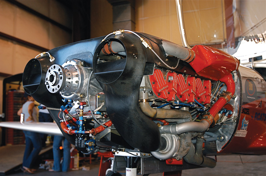
One Experimental gearbox that’s done well is the spur gear on the Thunder Mustang. Mounted to the Falconer V-12 and rated to 1200 hp in racing trim, the unit continues to see detail improvements from Thunder Mustang, who offers it at a cool $25,000 for any small- or big-block Chevy application (the Falconer V-12 uses 90-degree small-block Chevy architecture). Oswald Webb, chief design engineer for GKN is credited with the design. Interestingly, Webb worked on the Rolls-Royce Merlin reduction gearbox in his younger years. Clearly the design employs extensive lubrication and cooling, judging from the forest of external oil lines running over it. John Parker at Thunder Mustang says oil pressure/volume was reduced and scrapers added to avoid flooding the gearbox and improve drain back; overall reliability is excellent. Reduction is 2.8:1 and a quill shaft is fitted between the crankshaft and drive gear to absorb torsionals.
Rarely seen, it is possible to use two idler gears locked to the same shaft to separate half (one direction) of the gear loads from each idler gear. Such an arrangement also allows for two different gear ratios between the crankshaft and propeller for large gear reduction ratios.
Still using gears but a totally different design, planetary gearboxes are commonly used in automotive automatic transmissions, and are the design Lycoming employed on the GO-480 (Continental favored spur gear drives). Planetary systems use a gear with external teeth on the crankshaft, a large gear with internal teeth surrounding the crank gear, and a series of smaller, external-teeth gears in between, meshing everyone together. The crank gear simply rotates, thus racing the series of smaller gears around the inside of the large outer gear (other rotational arrangements are possible, but this is a common layout). Planetary systems are quiet, keeping the propeller and crankshaft on the same centerline and rotating in the same direction. Planetary systems can also be very strong, but they are a bit complex, and tend toward weight. Planetaries were nearly universal on big radials because they packaged well and easily accommodated a torquemeter—a small hydraulic system that told the flight engineer how much power the engine was making. That was important for setting power, checking fuel consumption, and analyzing engine health.
Direct Drive: The Practical Choice
Getting back to the general aviation mainstream, direct-drive engines bolt the propeller directly to the crankshaft, so the engine and propeller always rotate at the same speed. It doesn’t matter if a fixed-pitch or constant-speed prop is used, direct-drive means the engine and prop are bolted together in lock step.
If this isn’t the most engine- or propeller-efficient method, it does boast one of the greatest advantages: simplicity. There is no gearbox weight, no budget-busting cost of carefully designed and manufactured gears, no gearbox lubrication to consider, no gearbox to overhaul at TBO, no offset thrust line, and the engine is physically more compact.
Perhaps of greatest concern to a pilot, direct drive means no operational limitations due to gearbox longevity concerns, namely keeping the engine driving the propellers, even during descent and landing rollout.
Like so many things, direct-drive engine/prop combinations may not be the engineering or physics ideal, but they are to a surprising degree the practical winner. And we’ll close by noting that direct drive favors large-displacement, low-rpm engines to make useful power—another reason such engines are the general aviation norm.
“Just Don’t Do It!”
Having destroyed itself for the umpteenth time, the original, planetary gearbox version of Darryl Greenamyer’s 550 Continental sits broken in a Reno hangar.
Designing and developing a gearbox for hero-class performance requires hero-class engineering. For proof, just ask Andy Chiavetta, fabricator and crew chief to the gods at Reno and elsewhere in performance Experimental aviation.
Teamed with racing great Darryl Greenamyer on “Race 33,” a storied Lancair Legacy, Chiavetta was handed a lifetime’s worth of sleepless nights and trashed machinery attempting to build a superior gear-driven Reno mousetrap.
Two designs were attempted. The first was a custom planetary unit welded right to the front of the TSIO-550 Continental’s case. It was a sexy looking thing full of macho gears and their stout supporting cages—and a two-hour lifespan. Three times the gearbox failed before Reno and then again at Reno. Each time the engine case had to be split to access the carnage…
Harmonics were the culprit. Vibrations would crack the planetary cage, allowing the gears to cock sideways with predictable mayhem. Eventually the engine case and gearbox were re-machined to allow separate access, but the gearbox never lived more than two flight hours.
Tiring of that, Greenamyer and Chiavetta next opted for a Continental GIO-520 with its integral spur gear drive. “But it’s designed for a specific prop and weight. We put an MT prop on it…so you’re experimenting again. It would tear the accessories up in the back of the engine. It was just one trouble after another,” Chiavetta said.
After years of gearbox issues, the team had nothing to show for it. Greenamyer retired from racing—with seven Unlimited class wins let’s not forget—and Race 33 is poised to return with a new owner and conventional direct-drive Continental this year.
Even after the endless work, giving up on the geared engine wasn’t easy for Chiavetta. “It was hard to pull the plug on it because there is potential there. It makes sense, but takes a lot of engineering to make it work.”
Eventually Chiavetta researched the issues Lycoming and Continental had developing their geared engines decades ago and came to the same conclusion we heard repeatedly from those with gearbox development experience: geared performance is real, but geared drive development demands deep resources by pros. Chiavetta’s final advice to fellow amateurs considering a gearbox program was direct and firm: “Just don’t do it.”
Rotax: The Factory Gearbox
Today there’s just one major aviation piston engine builder making PSRUs standard equipment: Rotax. Champion of the small, efficient 4-cylinder, Rotax offers several variations of a spur gear drive, differing in narrow and wide gear widths, and reduction ratios.
Besides the spur reduction, Rotax’s drive also uses a simple dog clutch engagement between the short prop shaft and the spur gear, and may also feature a multi-disc overload clutch. The latter looks just like a motorcycle or automatic transmission clutch pack with alternating “steels and discs.” It’s there strictly to limit impact damage back into the engine in case of a prop strike.
The dog clutch is where Rotax handles torsional vibration by allowing minor decoupling of the engine and prop. The dog clutch has been offered with 15 degree (early) and 30 degree (late) angled ramps. Upgrading to the later angle is part of a TBO extension offered in a service bulletin, the other major TBO increase requirement is fitting a late-model propeller shaft with an extra lubrication hole. Generally speaking, the late-model Rotaxes feature TBOs in the 1200- to 1500-hour range; the 912 ULS is rated to 2000 hours.
There is a gearbox inspection at 600 hours or a littler earlier if avgas is used. That’s because the lead in avgas sludges in the tight clearances of the overload clutch.
Rotax makes recommendations on propeller selection, with the main idea of avoiding too heavy a prop. This is not difficult as the composite props generally used are within the weight limits. Such composite props are also frangible in a prop strike; while inspections are still required, internal engine damage is very rare with a composite prop strike.
Again, the Rotax engines are compact with relatively short, stiff crankshafts and are coupled to lighter-weight propellers. This somewhat limits torsional forces, and coupled with the dog clutch and extensive testing by this well-funded corporation means Rotax gearbox issues are unusual, as long as their recommendations are followed.


This PSRU article was well written and should be read by anyone wanting to add a reduction gearbox to an auto engine. There is no simple answer to overcoming torsional vibration an interaction of reducing the speed of an aircraft propellor when coupling it to a gearbox and a higher revving auto engine.
“Well engineered” redrives have been failing unexpectedly for decades, which means that there is a common hidden factor not being adequately considered. This culprit can stay hidden because it creates combinations of chaos. Instead of torsional vibrations and harmonics alone, the issue may frequently be transitory combinatorial loadings, ‘aided and abetted’ by the one thing we never seem to read about on this topic: gyroscopic moments of inertia. Spinning props are an incredibly powerful gyroscope that try to avoid changes to the alignment of their axis. They are being told to do so anyway, by forces that are a multiple of the weight of the aircraft and a lever arm that reaches to the CG… wherever that happens to be. These factors are not front and center for the engineer working a gearbox in isolation. They appear to be totally unconsidered for a large number of PSRU designs, including some pictured in the article.
To relate to this issue better, picture the prop/gyroscope instead as a solid concrete wall that we can hoist our airplane up against and attach our prop flange to it. (Imagine the wall attachment point has a bearing in it, so we can run our engine, through our freshly CNC’d belt drive/gearbox awesomeness.) Now start the engine, and shake the plane in turbulence. Go ahead, give it a few Gs.
Oh? Unexpected issues? Let’s change our expectations.
I keep looking at Ford’s two liter four cylinder crate engine from the Mustang that is supposed to make 310hp at 3,000RPM.
Seems like a good option to go the simple direct drive route.
For the low, low price of $6595!
A 74″ prop would have a fair amount of leeway for the tip speed at 3,000RPM, at about 0.86 Mach.
BMW put a bunch of Guibos on their cars. Would that isolate the prop well enough from the engines harmonics and vibration?