
A very common 0 to 1 mA analog pointer type meter. Next to it is a rotary switch that is used to select volts-amps-ohms or the range of volts or amps.
When last we left our little analog panel current meter, we said that it would deflect a needle when an electric current was passed through it. And so it will, but that doesn’t make a multimeter. It doesn’t even make us a current meter that will measure any more than one basic current. The first step to convert that meter into a multimeter is to figure out how to make the meter read various full-scale currents. For example (and we will use this example throughout this column), if we have a meter that reads one milliampere (1 mA) full scale, we might want to be able to read 10 mA, 100 mA, 1000 mA (1 ampere), or 10 amps full scale. We can do that fairly easily.
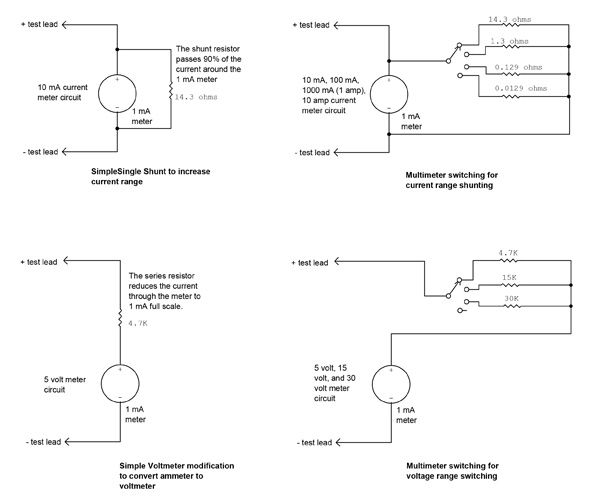
Here’s the deal. We simply put a “shunt” resistor across the meter so that (for example) 9 mA is shunted through the resistor and 1 mA flows through the meter. We have just made a 10 mA meter out of a 1 mA “movement.” The problem comes in calculating the value of the shunt.
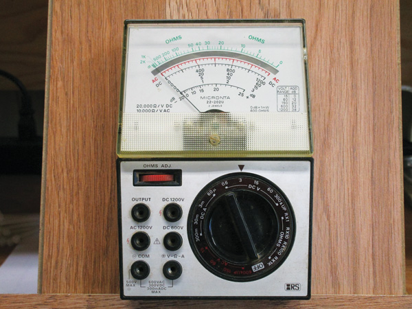
A typical analog moving-needle type multimeter vintage 1970 or so.
Remember that we said that what makes the meter deflect is a current passing through a coil of wire in a magnetic field. That coil of wire has a resistance, and the catalog lists the resistance of this particular meter (which we call the internal meter resistance, or Rm) as 129 ohms. There is another number we need, and that is what we call the multiplication factor. In this case we have a 1 mil meter that we want to read 10 mils on, or a multiplication factor of 10 ( 1 mil * 10 = 10 mils). We call this factor “n.” The value of the shunt resistor (Rs) is given as Rs = Rm / (n-1). Plugging in numbers we find that the shunt resistor should be 14.3 ohms (14.3Ω).
Now we get practical. 14.3Ω is not one of the normal “cheap” little carbon resistors that are a penny apiece. It gets down to what sort of accuracy you are willing to accept. If you use a regular 13Ω carbon resistor, the full scale will actually be 10.9 mA plus or minus the tolerance of the resistor, 5%. The actual reading, then, could be from 10.3 to 11.5 mA. You could use a standard 15Ω carbon resistor and the actual reading including tolerance would be from 9.1 to 10.08 mA.
Multimeter evolution.
Of course, if you want 100 mA full scale, you would use a 1.3 ohm shunt. 1000 mA (1 amp) uses a 0.129Ω shunt, and our 10-amp meter uses a 0.0129Ω shunt. Since I’m simply trying to tell you how it works, you don’t have to worry about where you are going to get these oddball values. What you do have to worry about is how to get all these different currents into a single box and switch select between them. Let’s worry about that in a little bit.
First, let’s convert that meter into a voltmeter. Since the ammeter measures current in series with the circuit, we might expect the voltmeter to measure voltage in parallel with the circuit. And how do we convert a voltage into a current? Did I hear the “A” students say “resistor”? Yes I did.
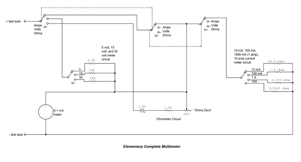
Elementary complete multimeter.
The fact of the matter is that we have a built-in resistor in the basic meter movement, and that is the internal meter resistance (Rm) we discussed above. With our 1 mA meter with Rm = 129Ω, Ohm’s law tells us the E (voltage) equals Rm times 1 mA, or 0.129 volts. That’s not a tremen-dously useful voltage for us in normal troubleshooting. How about we make a voltmeter with full-scale readings of 5 volts, 15 volts (for 12-volt aircraft), and 30 volts (for 24-volt aircraft)? Turning Ohm’s law around to get the value of our “multiplier” resistor, we ask what resistor will allow 5 volts to flow 1 mA. The answer according to Ohm is Rv (voltage multiplier resistor) is equal to 5 volts divided by one milliampere, or 5000 ohms. However, we have to take the Rm out of that 5000Ω, or 4871Ω. Again, this is an oddball value, but what would happen if we used a common 4700Ω (4.7kΩ) carbon resistor? The full-scale voltage would then be 4.83 volts (pretty close) with 5% resistor tolerances again setting the full-scale voltage from 4.59 to 5.07 volts. Those meter multiplier resistors for 15 volts will then be 15kΩ – 129Ω = 14871Ω, and 30 volts will be 30kΩ – 129Ω = 29871Ω. Both of these two are very strange values, but at these levels, a 15kΩ resistor gives a full-scale voltage of 14.9 volts (very close) and a 30kΩ resistor gives a full-scale voltage of 29.9 volts (very close).
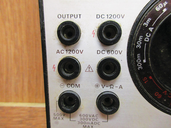
The first problem is to remember what all of these inputs do and where to plug in the probes for your measurement.
Let’s combine those two ways of using our homebrew circuit into a single box with a switch to go back and forth from volts to amps. That makes two-thirds of our multimeter.
Now let’s add a battery and a series resistor. The most common battery that we can easily get is the old reliable 1.5-volt flashlight battery. However, if we put the flashlight battery directly across our little meter it will cause (1.5 volts divided by Rm of 129 ohms) over 11 mA of current to flow through our meter, way too much. To reduce the current down to 1 mil, we will have to put a total of 1500Ω in series with the battery and the meter. 1500 – 129 means a fixed resistor of 1371Ω. How about we put a 1000Ω fixed resistor and a variable of 500Ω in series.
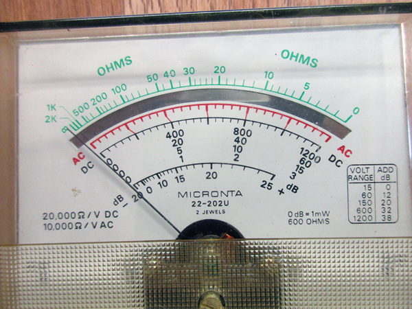
The second problem is to figure out which scale you need to use to get a correct reading.
We now have the basics of an ohmmeter. With the circuit completely open (infinite resistance) the meter rests on “zero.” With the test leads shorted together and the 500Ω resistor adjusted for full scale on the meter, now any additional resistance between the test leads will read somewhere between zero and full scale, and we have a real ohmmeter.
That gives us the three functions of a basic multimeter: amperes, volts, and ohms.

Now try and figure out which range and what type of measurement you are trying to make.
I think it is very important that you understand a basic analog multimeter before we start talking briefly about how things are done today. We can use a few simple electronic devices like a transistor or an op-amp to make our meter more sensitive, less of a load on the circuit, and use a lot less current than this analog meter. But it is important to understand the idea of a current shunt or a voltage multiplier resistor before we get more complex.
The next in this series will be to see how measuring a circuit might upset the circuit, what loading does to a circuit, and how to keep from sending the fuse maker’s kids to Harvard. How about a side trip into the world of complete system surge protection and chemical fuses? A bit of dalliance into electronic stall warners? It’s all good. Stay tuned.

![]()
Jim Weir is the chief avioniker at RST Engineering. He answers avionics questions in the Internet newsgroup www.pilotsofamerica.com-Maintenance. His technical advisor, Cyndi Weir, got her Masters degree in English and Journalism and keeps Jim on the straight and narrow. Check out their web site at www.rst-engr.com/kitplanes for previous articles and supplements.


