I really enjoy passing on the love of aviation to young people. I fly Young Eagles every chance I get and recently decided to immerse my granddaughter in aviation. For her first birthday, I bought her a plush Dusty Crophopper from the Disney movie Planes. This year was her third birthday, and I thought she might be old enough for a pedal plane.
I bought the plans for a Christen Eagle from Aviation Products (www.pedalplanekits.com) when my youngest son was about 3. I was still building my Cozy, so I didn’t have time to build both. The Cozy took priority, and I never built the pedal plane. I hung on to the plans, just because. When my granddaughter showed some interest, I decided it would be worth pursuing. I hoped she would appreciate the gift.
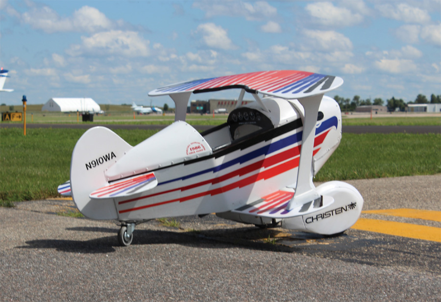
Landing gear and wheelpant parts with bearings.
The plans from Aviation Products are amazing—very detailed and complete. They outline everything that needs to be done. Aviation Products also offers kits for things that some builders may not feel comfortable fabricating. I thought I would be able to fabricate the whole aircraft myself. I have moderate woodworking skills, OK metal fabricating skills, and adequate welding skills. I thought I could build the plane in about four to six weeks, so I backed up six weeks from her birthday and got started.
The first thing I needed was a sheet of 3/8-inch AC plywood. None of the building centers in my area stocked it, so I special ordered it. I knew I needed AC to get a smooth surface for the pilots to touch. A lower quality board would be too rough. I also bought the metal and a 1×10 board for the wheelpants and nose.
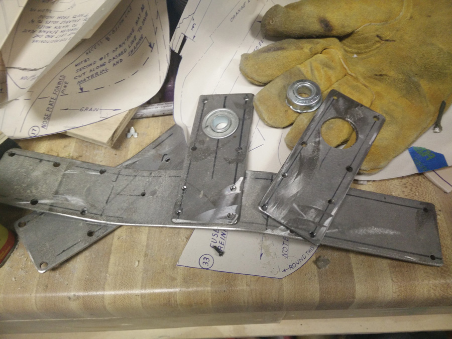
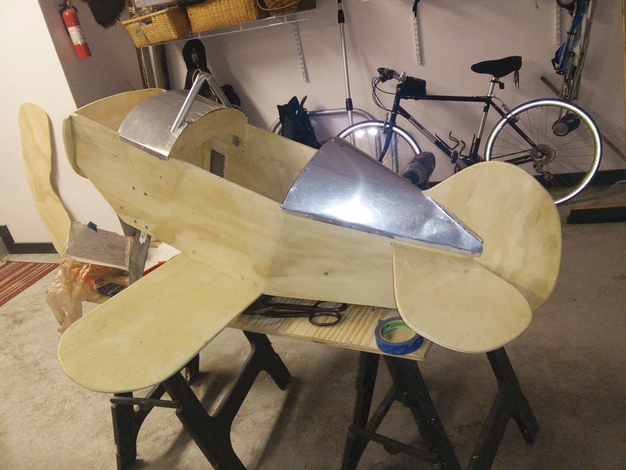
Fuselage after initial sawing with bulkheads in place.
Control System, Landing Gear and Crankshaft
I started working on the gear legs and the controls. The controls are made from thin-wall conduit, which is very easy to fabricate. Cut the tubing to length and squash the ends where the bolts will connect the parts together. There is a bellcrank that needs to be welded, so this was my first chance to try some welding on this project. I did an adequate job, and it came out quite strong, but I had things out of phase, so it had to be redone. After getting all the controls done, I made the two cabane struts, again out of conduit. Some bends around a squashed section in the middle where the wing attaches came out very nice.
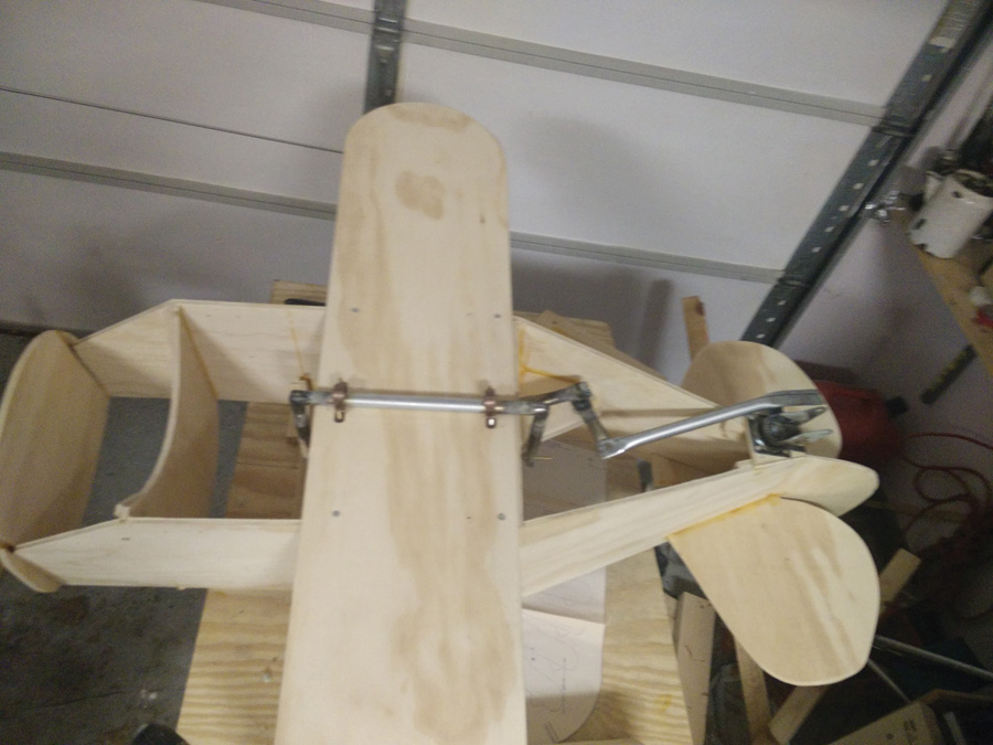
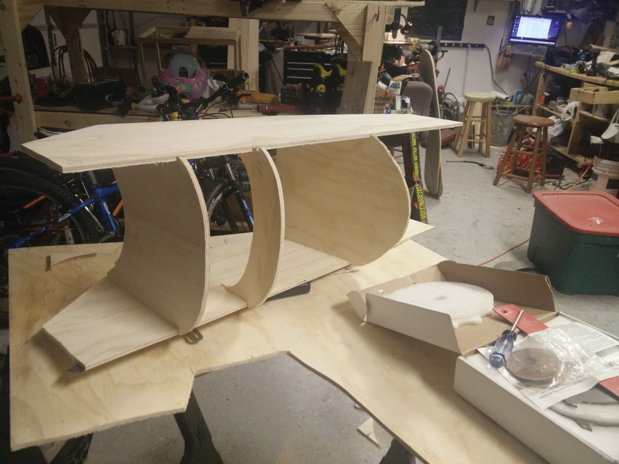
Test fitting the control system.
Next, I started on the landing gear struts. I followed the plans, and because I hadn’t purchased the wheels, I didn’t know how big the bearing was going to be. Once I found the right sized wheels, I found the plans were correct, and I was able to put the wheel bearings in place without any modifications. The drive wheel has both bearings removed and a nut welded to a washer for the replacement. The nut screws to the pedal crankshaft, and another nut has the threads drilled out. Welding the wheel was tougher than the conduit. The sheet metal used for fabricating the hub of the lawnmower wheel is very thin, and the washer is about four times thicker. Managing the heat was much harder.
Fabricating the crankshaft for the pedals was a fun challenge. I had never tried to bend solid half-inch bar stock like that. Building a jig was the key, and using lots of heat at the bend locations made it come out pretty accurate. Afterwards, cutting to length was done with an angle grinder. One end is threaded for attaching to the drive wheel.
Fuselage, Tail Feathers and Wings
The plywood showed up about this time. The plans come with full-size templates, so laying out the parts is easy. I taped the templates to the plywood and traced them. Where the plans had straight lines, I used a straightedge to be sure everything was as straight as possible. I did most of the rough cutting with a sabre saw, and then finish cutting on a band saw. Some parts wouldn’t fit in the band saw, so I put a finer blade in the sabre saw and cut closer to the edges.
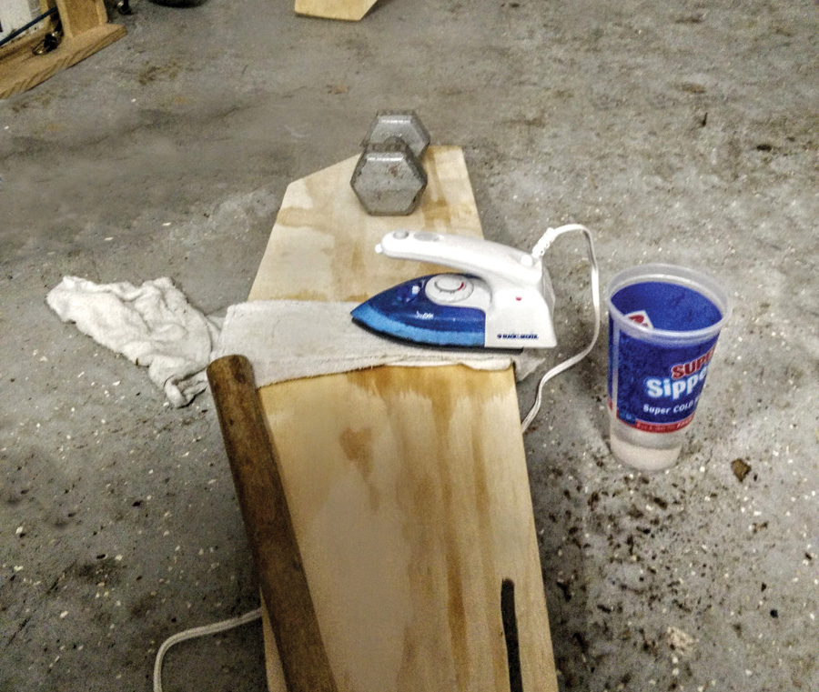
Sides are bent using an iron and wet cloth.
The fuselage sides have dados for the bulkheads and a bend just behind the cockpit. I cut the dados on a table saw. The plans have you build a jig for the bend, then suggest using an iron and wet cloth to steam the area. I thought bending the plywood fuselage sides would take hours. Using the method suggested, it took about 15 minutes per side. I left each side under pressure overnight.
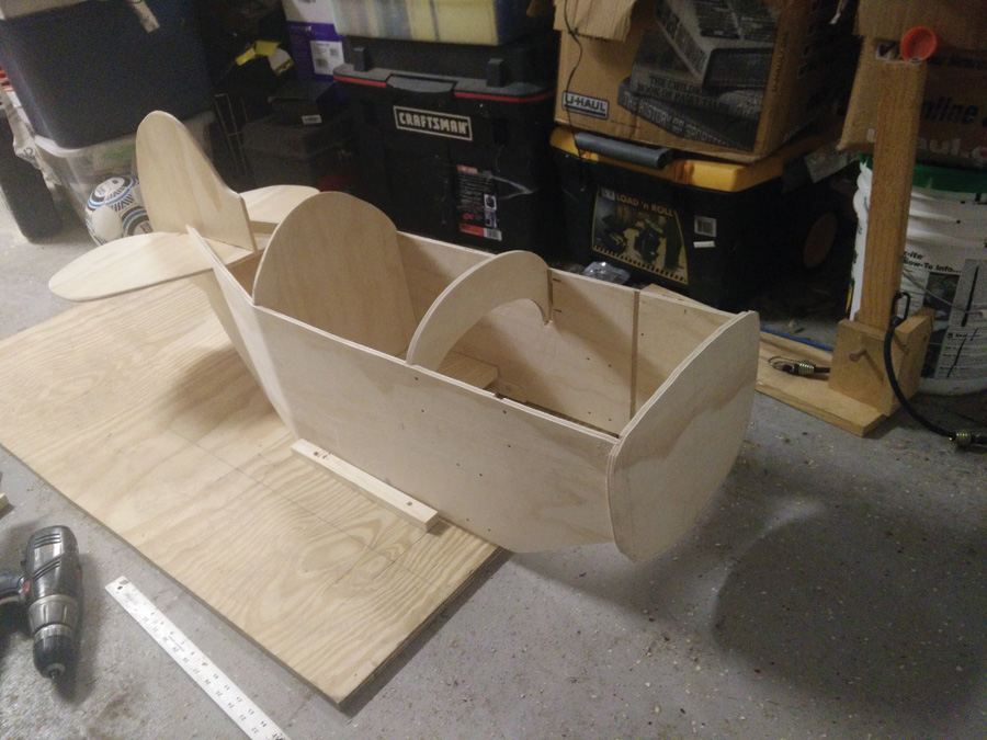
Fuselage in jig for alignment.
With all the parts cut and fabricated, I could start assembly. There was a fuselage assembly jig in the plans that was ideal for getting everything square and tight. That assembly was critical for later steps. A little gluing and clamping ensured the fuselage and bulkheads were assembled square in all directions.
Initial assembly is square and tight.
The joint used for the rudder and horizontal stabilizer was perfect if cut correctly. I was shocked how tight, square, and well locked it was when I first dry assembled it. I considered not gluing the joint because it was so hard to get apart. I did finally get it apart and glued properly. The slot in the back of the fuselage needed no additional trimming when I slid the tail assembly in place.
Removing the fuselage from the jig only took a couple screws. I was able to work on the bottom of the fuselage at this point. There was a block that needed to be fabricated out of two pieces of
plywood and four dowels for the bellcrank. Clamping and gluing allowed that part to come out strong, then it was screwed to the seatback bulkhead.
Many parts are assembled with hardwood dowels, as the places where screws will penetrate the plywood from the side may cause the plys to split. The locations in the plans are exactly where they need to be to prevent the split and give a strong joint. I wanted to be flexible and wait until assembly before committing to the dowel location, but the location worked out to be in the correct place every time.
By following the plans, the rear cover and mid cover fit well.
The wings and parts of the fuselage need the edges rounded. Using 80-grit sandpaper and a good sanding block made all of the edges round. Most of the plywood shaping was done by hand with the block. It wasn’t hard and gave me control to not sand where I shouldn’t.
The plans insisted on making everything soft for the pilots of this airplane. Most of the screws were flush, with some round head. The sharp pointy end never protrudes where the pilot can come in contact with it. The threaded bolts in the landing gear struts were almost flush when coming through the steel. Even in places where little mechanics might want to fiddle with things, there was nothing that should hurt them.
The gear legs went into the holes in the sides of the fuselage exactly where they were drawn in the template. I didn’t always get the holes in two parts exactly where the plans drew them, but the holes had enough tolerance to allow assembly to be completed. The gear leg has a wheelpant bracket as part of the design. This bracket is also where the crankshaft bearings attach. The designer thought that some pilots might be shorter than others, so the gear legs have two sets of holes. The top holes allow the pedals to be closer to the pilot, and the bottom holes allow taller pilots to have comfort. As the pilot grows, the position can be adjusted.
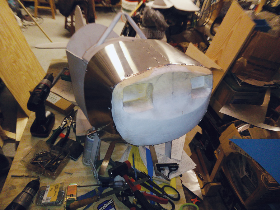
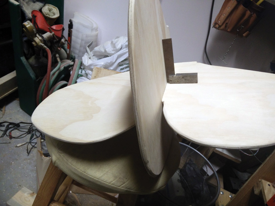
Rough shape of nose bowl with cowling fitted and riveted.
Wheelpants, Cowl and Tail Fairing
Fabricating the wheelpants and nose took some real woodworking skills. Both the wheelpants and forward section of the cowl are laminated 3/4-inch pine boards that need to be shaped. I tried spokeshaves, chisels, and various planes, but settled on a power belt sander with 40-grit sandpaper for most of the shaping. The belt sander worked, but I am sure there would be better ways to do it. When I was done, I had a couple inches of dust on everything in the garage.

Wheelpants before and after rough shaping.

Shaping with a sander leaves a mess.
When all the wood was shaped and assembled, the sheet metal work began. The top and bottom of the cowl are covered with an aluminum skin. The plans have patterns for all the aluminum parts as well. The rear part of the fuselage was the first part I covered. The pattern was spot on and took no more trimming than the instructions said it might. The mid-cowl has a cabane strut through it and required oval holes. This worried me; metal to metal, there isn’t much forgiveness, but again the patterns were spot on.
The lower cowl was flared around the exhaust area, and the bending tool was built according to the instructions. This bending tool was used around the edges of the top cowl as well, so there are no sharp edges exposed for little pilots or mechanics to get cut on. Something didn’t quite work out with my top cowl, and I needed to split it and splice a section of scrap aluminum to make half of the cowl fit. I chose to rivet these parts together and make it look like it was hinged.
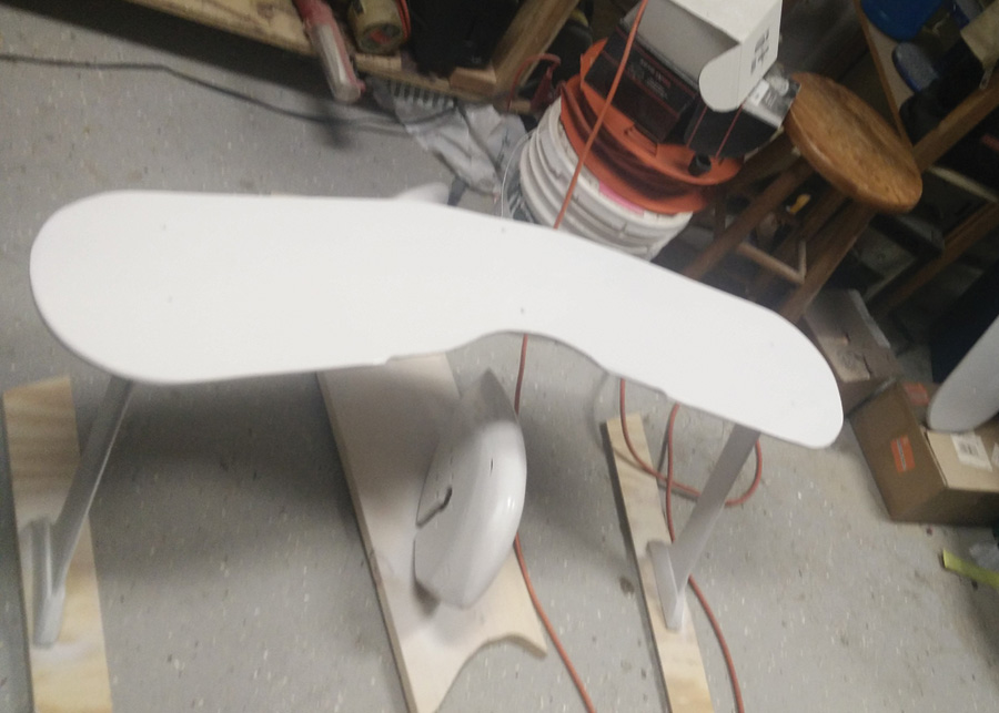
Wings and wheelpants after painting.
Finishing Touches
All the wood needed to be sealed. A good, high-quality sanding sealer is recommended. I put on about 2-1/2 coats, using all of a quart to cover the inside and outside of all the wood (the inside didn’t get a full coverage of the last coat). The metal needed to be primed before painting; I just used a rattle-can grey primer for the steel and aluminum.
The airplane was partially disassembled before painting. The plans recommended using an aircraft paint, but I chose to use a common hardware store lacquer paint (Rust-Oleum). I sprayed the plane in my driveway using a large drop cloth and a simple paint gun.
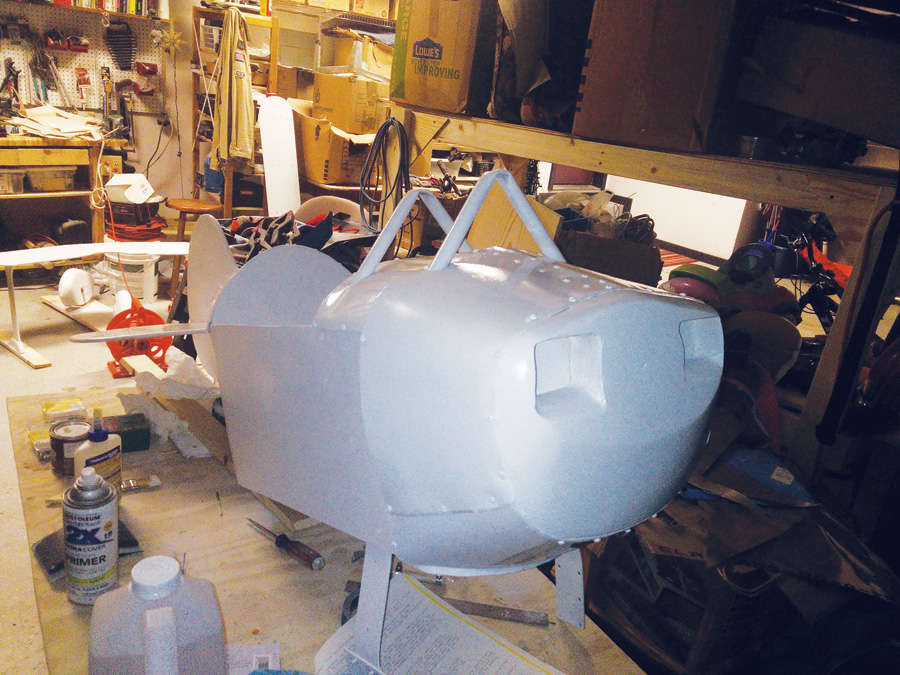
Fuselage after painting.
After painting there were items that needed to be added. The cockpit is lined with a coaming made of air hose. There is also a bit of air hose above the cockpit on the back of the top wing. I’ve seen my granddaughter bump her head into the back of the wing, so this was an excellent design enhancement.
The wheels and the wheelpants have very little tolerance, but the welding, crankshaft bending, and assembly had an accumulation of errors. Aligning the wheel flaw opposite the crankshaft flaw was the best way to make the tolerance acceptable. At worse, there was about 1/4-inch runout; at best, I got it down to less than 1/8-inch runout.
Reassembly took much longer than I anticipated. Many of the screws had never been installed. I needed to be careful to not scratch the paint replacing the hardware in the various parts of the plane. The birthday party was to be on Saturday, and I was still assembling late into Friday night.
At the party, my granddaughter’s best friend jumped in first. Both my granddaughter and her friend really seem to like it. The seat only holds one, and they took turns for a while. Eventually one or the other seemed to like wing walking. I hope it brings them many years of service.
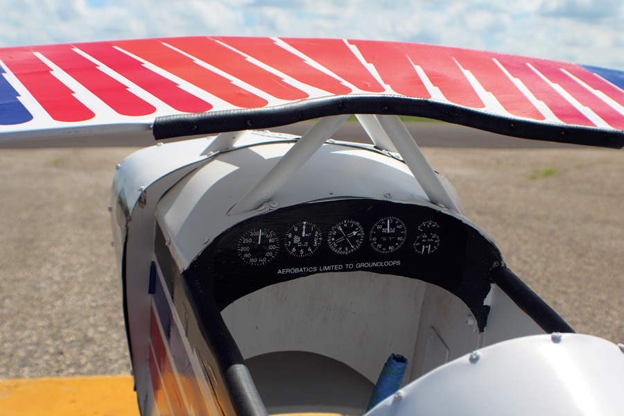
Cockpit view shows the coaming made from air hose and VFR instruments on the panel.
The decals didn’t arrive until the day after the party. No one seemed to mind a plain white airplane. When the time worked out, I brought the plane back and put the decals on. They really add to the looks and make it a more colorful airplane.
In the end, I didn’t care if anyone liked the plane; I really enjoyed building it. The building process brought me back to building my Cozy, and it gave me a sense of accomplishment every step of the way. The plans are very complete and outline everything that needs to be done.
Preflight is easy since the aircraft is below the pilot’s shoulder. Simply glance at the tires and pedals, and you’re done. Climbing in can be accomplished from either side. Standard procedure is to step on the wing, throw a leg over the side, step on the seat, and then the other leg can come in. The center stick and pedals are in mostly standard locations.
The single-axis control stick (tailwheel only) minimizes any risk of stalls or spins. Control harmony is ideal, and stick forces are easy to manage. Basic VFR instruments add to the pilot’s ability to imagine how well things are going.

Instead of a conventional throttle, power is regulated by dual foot pedals. At startup the pilot simply presses on the higher pedal to get the aircraft moving, and the flight can continue until nap time. The standard LG-2 (two legs) engine is adequate for straight-and-level travel at leisurely cruise speeds, but is somewhat underpowered climbing hills. Auxiliary pusher power is activated by shouting out to Grandpa or a nearby parent.
Range is typically about two blocks, with no reserve. Longer flights are possible, but are typically limited by the strength of the pilot’s legs and the length of their attention span. Once the flight is complete, the shut-down checklist is extremely short:
• Stop pedaling.
• Let someone else have a turn.
• Don’t leave the plane in the driveway or on the sidewalk.
For aviators who are small enough to fit into the cockpit, few other aircraft are likely to be so much fun.


Awesome article! I think that this would be an excellent next step after a Young Eagle flight.
Perdon Tom
muchas gracias por compartir
es factible que me diga la dirección en la cual puedo comprar los planos
Saul, plans can be purchased here: https://pedalplanekits.com/
Is there a way to reach out to you? I would love to do a project with at risk youth around aviation.
After having the pedal plans/kit for almost 30 years, I finally started it when my daughter was turning 24:) She turns 29 next week. In the meantime I did build a full-size Baby Great Lakes, so I have a bit of an excuse. I figure this will be ready for grandchildren. I purchased the hardware and metal kits – glad a I did!