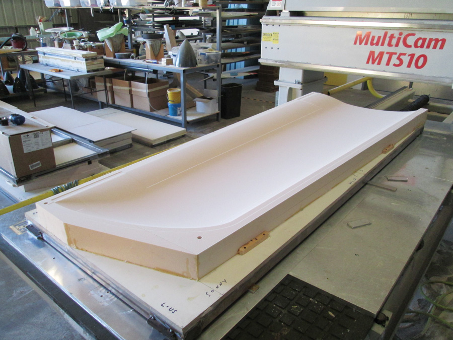
Wing mold for the author’s SR-1 speedplane after machining at Catto Propellers. Although Catto primarily uses its CNCs for propeller manufacturing, the large table size makes them perfect for wing molds.
Last year we featured a pair of articles [“Fifties Fuse, Teeny Wings,” March 2015 and “Black Beauty,” April 2015] that provided an overview of fabricating a Formula 1 raceplane wing using CNC-based rapid prototyping. The scale of the project was too large to get into the nitty-gritty details, but in this series of articles we’re doing just that—and a lot more. We’ll look at making a mold blank, familiarizing yourself with the materials and methodology vis–vis coupon testing and, finally, provide a detailed, step-by-step procedure for making a vacuum-bagged part such as a wing. We’ll also provide a video link where you can watch a typical layup.
In this first pair of articles, we are going to look at the use of lightweight tooling foam in (relatively) inexpensive, non-production-quality CNC molds for vacuum-bagged parts. (By non-production quality, we simply mean that the number of parts you can expect to make from these molds is limited; they are best employed for prototypes, one-offs, or parts made in small quantities.)
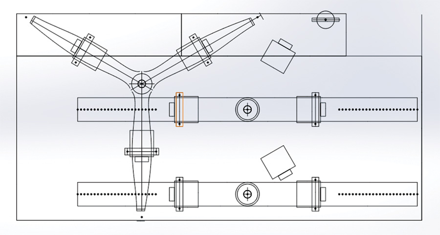
A model of the CNC table part attach points can help when determining dimensions of the frame. (Courtesy of Catto Propellers)
With the costs of CNC machines and concomitant shop rates dropping to a point of affordability for the average amateur aircraft builder, it is now possible to fabricate your own molds for composite parts at a reasonable price. Producing such molds is basically a three-step process: First, the molds must be designed with a 3D computer aided design (CAD) program like SolidWorks or Inventor. Next, mold blanks are assembled. Finally, the mold blanks are mounted to a CNC and machined according to a computer aided manufacturing (CAM) file generated from the CAD program.
Smaller block-shaped molds (i.e., for a spinner or wheelpant) can simply be bonded to a sheet of MDF/plywood, which is then bolted to the CNC table.

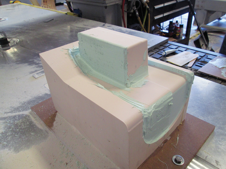
High-density (30-pound) mold finished with PPG DP90LV. Higher density foams finished this way obviate the need for the vacuum bag release layer used with lower density foams.
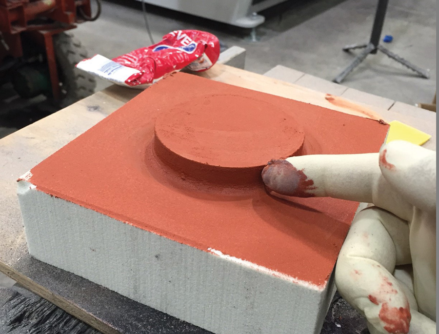
You can also get a nice finish by applying a thin coat of Evercoat Ever-Glaze spot putty with a squeegee, sanding to a smooth finish with 220 grit, and shooting with epoxy primer.
The first step—learning CAD/CAM—is not a trivial undertaking, but nor is it rocket science. For example, using tutorial books such as Paul Tran’s SolidWorks Part I: Basic Tools and Part II: Advanced Techniques, along with Matt Lombard’s excellent reference book SolidWorks Bible, you should be able to create advanced models in approximately 300 hours ab initio. If you have no CAD experience, teaching yourself can be extremely frustrating. In that case, I highly recommend taking a university or community college course to get started. This will also allow you to purchase the student versions of CAD software for hundreds of dollars vs. the thousands you would pay for commercial versions. An even better deal for EAA members is that you can now get a student copy of SolidWorks for free.
The last step—machining—is probably something many builders have some familiarity with, but we’ll also assume most of you don’t own your own CNC and will have a friend or shop do this for you. So the first and last steps are beyond the scope of this article. However, the middle step of assembling the mold blanks is certainly within the grasp of homebuilders, and is what we’ll cover here.
Step 1: Fabricate the Steel Frame
Once your part has been modeled in CAD, you will have a good idea of the dimensions of the foam blank and requisite mounting frame. The first consideration is how you will mount the mold blank to the CNC table. Most CNC tables will have threaded holes to which you can bolt your frame. The CNC operator should be able to provide you with a bolt hole diagram for their table. You’ll also want to find out the maximum x, y, and z axis travel of the tool head to ensure that your mold will fit within the parameters of the machine.
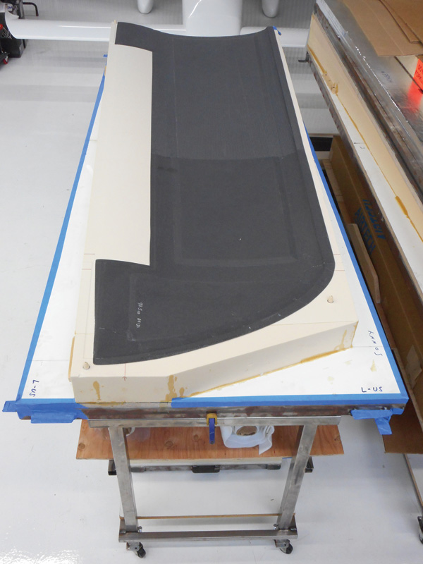
Although the wing mold is tapered, the frame itself is rectangular for ease of construction and alignment on the CNC table. The foam is cut as close to the mold shape as possible, since it is quite expensive. Foam cutoffs can be bonded into blocks for new blanks. Consider storage options when planning your molds. The rolling steel frame under the mold serves as storage and supports the mold during wing assembly. Shelves underneath provide storage space for layup materials.
For smaller block-shaped molds (for example, a spinner or wheelpant), simply gluing the block to a mounting board of MDF or plywood is sufficient. This base is then bolted to the table (don’t forget to leave enough edge room on your base for bolting), and you are ready to machine. Seal exposed wood as necessary to prevent warping that could be caused by moisture absorption.
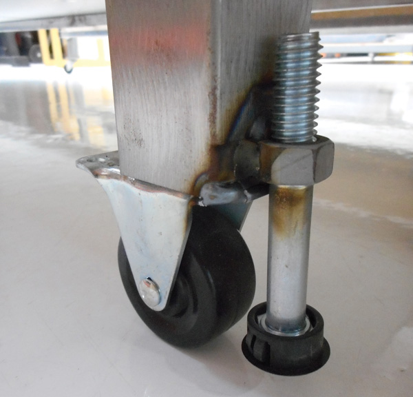
Retracting bolts allow the frame support to be precisely leveled when constructing the wing.
For larger objects, such as wing or fuselage molds, you will need a frame that ensures that the shape CNC’d while on the table is preserved when the mold is removed from the table, and will stand up to the rigors of layup, assembly, and storage. The easiest method is to simply weld the frame from 16-gauge (1/16-inch wall thickness) mild steel tubing. For smaller objects such as control surfaces or tail feathers, 1.5-inch square tubing is sufficient. For larger objects, such as a wing, use at least 2-inch square tubing, and/or heavier gauge tubing. One-inch tubing is too small and flexible for all but reinforcement or very small (less than 18 inches) molds, in which case it is generally easier to simply use a sheet of MDF as noted previously.
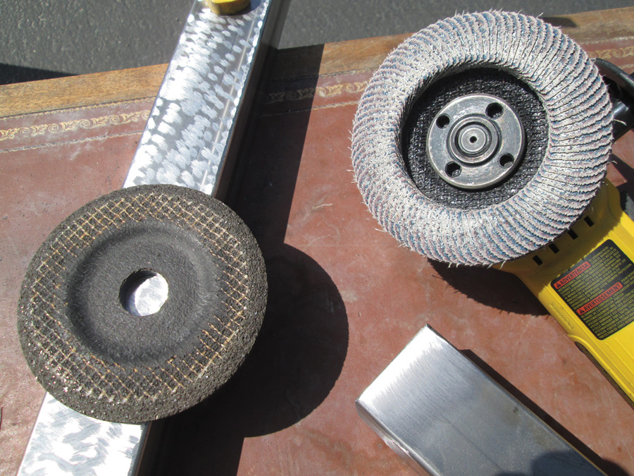
An angle grinder with an abrasive flapper pad is used to roughen up the frame before bonding on the MDF base. The flapper works great for most applications, but the cutting disk on the left can be used if serious metal removal is required.
If possible, keeping the frame rectangular, irrespective of mold shape, will help with positioning on the CNC table, by which we mean setting home (i.e., where the machine reads the zero point of the x, y and z axes) and establishing the orientation of the mold (i.e., aligning the x axis of the mold parallel to the x axis of the CNC machine). Non-rectangular molds may save a certain amount of weight and materials cost, but will require more time fiddling with alignment/orientation while on the table. Consider whether the material and weight savings are worth the extra time spent at the table. If you are paying for CNC time by the hour, a mold that allows quick setup will save you money in the long run. The downside of a frame that is larger than the actual mold is marginally greater cost and weight. The foam itself should be cut to actual mold shape in order to minimize waste, since it will be the most expensive material per square foot.
Two final frame considerations are how to incorporate portability and storage into the frame. Wing and fuselage molds can be extremely heavy and awkward to move, so consider welding handles of 1×1-inch angle to the frame. Molds can also be quite large, so give consideration to how you will store and stack them in order to minimize the shop footprint and also protect the mold surfaces (i.e., stacking wing molds face to face so that the vulnerable machined surfaces are facing inward). All handles, mounting feet, etc. should have rounded corners to avoid poking holes in humans and vacuum bags, and open tube ends should be closed to avoid sucking the vacuum bag into the frame.
Step 2: Attach the Base
Once the frame is welded, the next step is to attach the base. The base adds stiffness to the frame and provides a large surface area to which the tooling foam is adhered. MDF/melamine particleboard works well, since the homogeneous nature of the particleboard means it is usually quite flat, and the melamine acts to prevent moisture absorption and consequent warping.
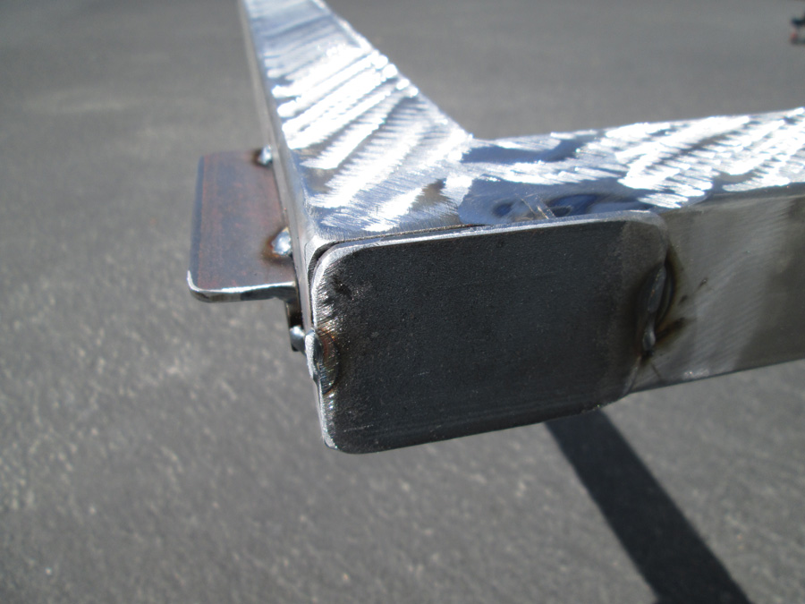
Round all sharp points that could potentially poke a hole in the vacuum bag. Here you can see a piece of angle iron tacked to the frame as a handle, as well as an end plate tacked over the open end of tubing to prevent the vacuum bag from getting sucked into the tubing. A well-constructed blank will prevent headaches when it comes time to vacuum bag. You’ll have plenty to worry about during a layup without chasing down leaks poked in your bag by the mold.
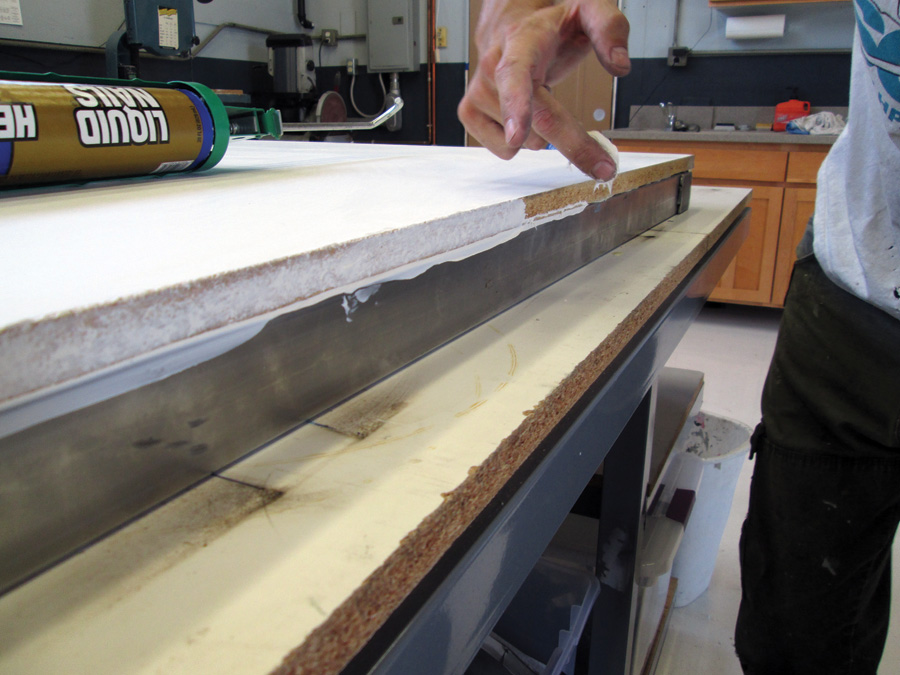
The melamine is stripped in the areas where it will be bonded to the steel frame with a 4.5-inch ceramic flap disc mounted to an angle grinder. Likewise, the frame should be lightly roughed up with a grinder wheel where it will be bonded to the base to ensure a good grab for the adhesive. The particleboard is then glued to the steel frame with construction adhesive and weighted evenly for a good bond. Once the adhesive has cured, use the remaining adhesive, or a latex acrylic caulk, to fillet the seams between the particleboard and steel frame, as well as the exposed particleboard edges, in order to minimize entry points for moisture that could cause warping of the MDF or rusting of the steel.
As mentioned previously, for small or block shape molds, the melamine particleboard serves as both frame and base when steel is not used.
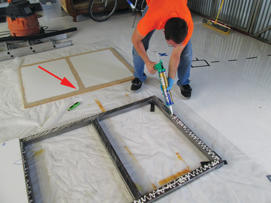
CalPoly Mechanical Engineering student and SR-1 Project intern Brian Paris lays down a bead of construction adhesive to bond the mold base to the frame. Note that the melamine has been sanded off the mold base bond line (see red arrow).
Step 3: Prepare/Attach the Foam
The final material to be added is the tooling foam. This article will assume the use of a high-density urethane foam such as Coastal Enterprises’ Precision Board Plus (distributed by Revchem Composites). Lower density foams (such as the blue or pink rigid extruded polystyrene [XPS] board available from home centers) will compress under vacuum and as such are not appropriate for vacuum-bagged parts, but are fine for non-bagged wet layups.
Precision Board comes in a large variety of densities, from 4 to 75 pounds per cubic foot. The price is approximately $6.00 per cubic foot per pound and is linear: 20-pound foam is twice the price of 10-pound, and 40-pound is four times the price. Forty-pound foam provides excellent machined surfaces with no visible porosity. Ten-pound foam, such as used on the F1 wing mold mentioned at the beginning of the article, is obviously much less expensive, can be moved without a forklift, but has visible porosity and is easily dented with a fingernail. As such, it requires extreme care in handling. Go with the highest density you can afford (and lift). Ten-pound foam is the absolute minimum recommended for vacuum-bagged parts, and will probably only allow for a few pulls (i.e., part layups) before “hangar rash” becomes a problem.
After bonding to the frame, you may wish to seal the edges of the base to avoid moisture absorption.
The Iscold F1 wing featured in last year’s article had four molds (upper surface left and right, lower surface left and right), each of which used approximately 12 cubic feet of 10-pound foam. So the 120 cubic-pound feet on each surface cost about $840, and each complete mold blank—steel, base, and foam—weighed well over 200 pounds.
Precision Board can be cut with typical woodworking tools like table or band saws; no special blades are required. The melting temperature of the foam is too high to permit hot-wire cutting. Note that Precision Board is not UV tolerant and will visibly tan very quickly (within minutes) when exposed to sunlight. Short term this does not pose a problem, but long term can result in degradation of the foam. Therefore you will want to store your foam (and molds) away from sunlight.
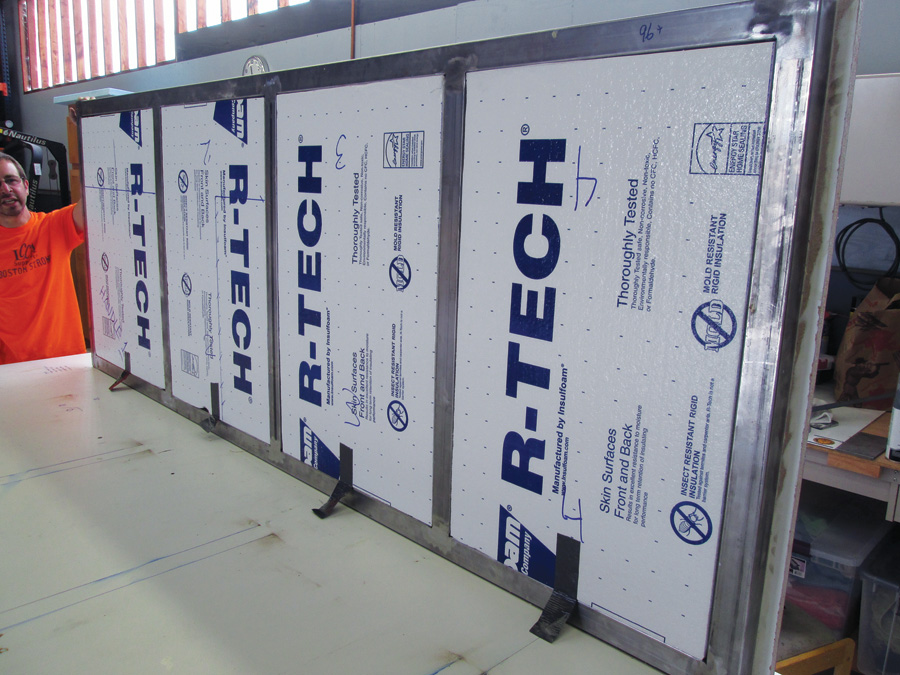
The tooling foam will be bonded to the frame using vacuum bag pressure, so it is necessary to fill the open frame space underneath with cheap insulation foam (otherwise the vacuum bag has a tendency to rupture when bridging large gaps between the steel frame and MDF sheet). The tabs at the bottom of the sheet are strips of duct tape to pull the foam out afterwards so it can be recycled on other molds.
Although the foam can be bonded to the MDF base with epoxy, this is unnecessarily expensive and overly complicated. Coastal Enterprises offers a one-part urethane adhesive that is faster, easier, and cheaper than epoxy. This adhesive is a moisture-cured isocyanate (i.e., expanding foam) that is applied to one or both surfaces to be bonded. The two surfaces are then clamped or vacuum bagged, with full cure occurring in approximately 240 or 30 minutes, depending on whether you use the slow (PB Bond 240) or quick cure (PB Fast Set). Because the PB Bond expands, small irregularities between the foam and base, or in the application of the adhesive, are filled by the expanding foam.

Precision Board is easily cut with a circular saw. A length of 2-inch steel tubing serves as a straightedge.
For small pieces, PB Fast Set and strong clamping provides excellent results quickly with a hairline bond width. For larger pieces, you will need to use PB 240 and vacuum bag the assembly (Coastal Enterprises web site has an excellent video on how to use PB adhesive, as well as a variety of other informational videos and literature on PB Board). Of course, in addition to bonding the foam to the base, you can use PB adhesive to join several cutoffs into one large block, or to make topographical blanks that economize foam usage.
Avoid the temptation to bond the foam to the base with construction or similar adhesive. You will not get an even bond line, and any unbonded pockets will deflect under the pressure of the tool head, ruining the accuracy of your mold.
That’s all we have space for this month. In Part 2 of this article, we will discuss vacuum bagging blanks to the CNC frame, mounting the blanks to the CNC table, and a few other options for rapid prototyping. Following that, we will then explore fabricating coupons, in order to dial in your layup process, as well as get a feel for composite structures.
![]()
Eric Stewart is designing and building the SR-1, a speed plane for setting records in the FAI c-1a/0 category (takeoff weight less than 661 pounds, including pilot and fuel). You can see more at facebook.com/TheSR1Project, including additional photos and videos of the subjects in this series of articles.


