Last month we started our look at propellers with idealized momentum theory. Momentum theory treats the prop as a magic disk that generates a force field that accelerates the air through it uniformly. While this is useful for getting an idea of the limits of propeller performance, it does not help in understanding the design of the actual propeller.
Real propellers are not magic disks. They are a set of blades that spin around the propeller shaft, driven by the engine. The blades interact with the air to convert torque into thrust.
Prop blades are often described as rotating wings. Aerodynamically, the blades do generate thrust by generating aerodynamic lift on the blade elements, in the same way wings generate lift. What is very different is how the flow conditions vary over the span of the blade.
On a wing, every element along the span sees the same oncoming air flow. Although induced effects and wing twist cause variation of apparent angle of attack along the wing, the inflow angle to the wing from the far field is the same over the entire span. Likewise, the oncoming air has the same airspeed, and hence, Mach number everywhere along the span.
This is not true for propeller blades. The prop is spinning around its shaft, while at the same time the propeller and shaft (and hopefully the airplane they are attached to) are moving through the air as a whole. The flow conditions at any point along a prop blade are the result of the combination of the velocity due to the spin of the propeller and the velocity due to the forward motion of the airplane. This causes large variations of both airspeed and inflow angle over the length of the blade.
A properly designed propeller needs to take both of these effects into account. We start by looking at the effect of tip speed on propeller design.
Blade Tip Speed
The airspeed of a blade element is the vector sum of the tangential speed caused by the rotation of the prop and the free-stream airspeed. Propeller designers are most concerned with the speed and, more importantly, Mach number near the tips of the blades.
The tangential speed of the tip of the blade of a propeller is given by:
Vr = πDN / 60 feet per second
Where:
Vr = velocity due to rotation
D = propeller diameter in feet
N = rpm
The airspeed of the propeller tip is increased by the forward speed of the airplane as follows:
Vt = SQRT (V2 + Vr2)
where V is the airplane’s airspeed in feet per second.
The tips of a propeller blade get going quite fast. Lets take, for example, an airplane flying 120 knots, with a 72-inch diameter propeller turning 2600 rpm:
D = 72/12 = 6.0 feet
Vr = 3.14159 x 6.0 x 2600 / 60 = 816.8 feet per second
V = 120 x 1.6867 = 202.4 feet per second
Vt = SQRT (816.82 + 202.42) = 841.5 feet per second
This is a tip speed of 499 knots.
What is more important is to compare the tip speed with the speed of sound. At sea level on a standard day, the speed of sound is 1116.9 feet per second, so our example propeller has a tip Mach number of 0.75, or 75% of the speed of sound. If the same airplane were flying at 15,000 feet, where the speed of sound is 1057.7 feet per second, the tip Mach number would be 0.795.
Figure 1 shows the variation of tip Mach number, rpm, and propeller diameter for our 120-knot example airspeed.
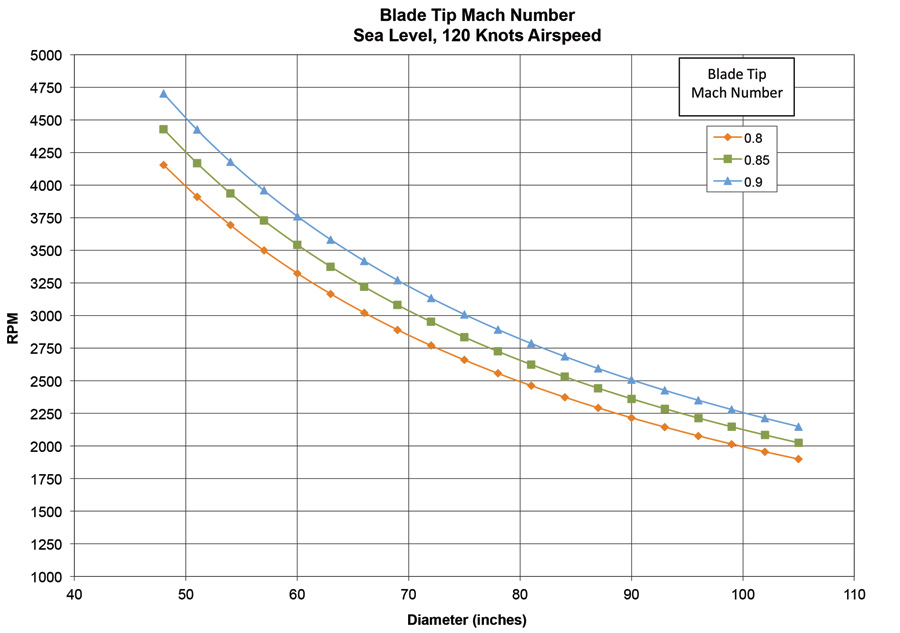
Figure 1: Blade tip Mach number, sea level, 120 knots airspeed.
Now let’s look at what would happen on a faster airplane flying at the 250 knots:
The tangential velocity stays the same, but the airspeed is now 421.7 feet per second. The tip velocity increases to 919.2 feet per second. The tip Mach number is 0.82 at sea level, and at 15,000 feet it is 0.87.
If we increase the propeller diameter of our 250-knot example airplane, the tip Mach number would rapidly approach sonic.
Airfoil performance generally starts to degrade as Mach number climbs above M=0.85, although some thin airfoils can retain good characteristics to higher Mach numbers.
In general, propeller designers try to keep the tip Mach number below about M=0.9. This tip Mach number works well for metal or composite propellers that can use thin airfoils near the tips. For wooden props, which have thicker blades, it is advisable to keep the tip Mach number down in the neighborhood of 0.8 or less.
Figure 2 shows the variation of propeller rpm and diameter for the M=0.9 limit condition for the two airspeeds considered above (120 knots and 250 knots). The figure illustrates one of the major problems facing propeller designers. The faster the airplane flies, the higher the free-stream Mach number is. This means that, for a given propeller blade tip Mach number, the allowable tangential speed is lower.
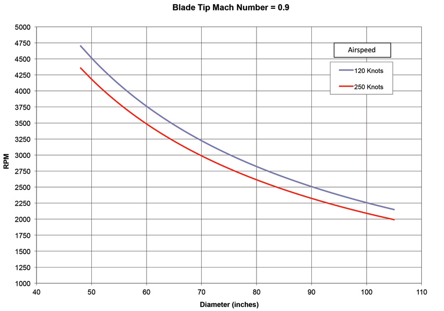
Figure 2: Blade tip Mach number = 0.9.
This phenomenon drives the allowable diameter and/or rpm of the propeller down as the airplane gets faster. Unfortunately, faster airplanes also tend to need more power than slow ones, so the prop designer is faced with the need to absorb more power with a prop that is either smaller diameter or slower turning than if the airplane were slower.
The problem is compounded if the airplane is propelled by a direct-drive piston engine, since the engine must turn its rated rpm to develop its rated power, and the prop turns at the same speed as the crankshaft.
At some point, the allowable prop diameter to keep the tip Mach number within limits is too small for the prop to absorb the required power with a realistic blade area. In this situation, the solution is to use a reduction gearbox to drive the propeller at a lower rpm than the engine. All turbines and some piston engines do this.
Very-high-speed propeller-driven airplanes (Like WW-II fighters) use large-diameter propellers to absorb the power. These turn quite slowly compared to the props on typical light airplanes to keep the tip Mach number subsonic.
Noise
In addition to hurting efficiency, high propeller-tip Mach numbers cause another problem: noise. As the tips approach the speed of sound, shock waves form. These make a lot of noise, as anyone who has seen the Samson “Big Pitts” biplane in action can attest. While a lot of prop noise may be a plus to some airshow audiences, it definitely annoys airport neighbors. As people get more noise sensitive and propeller designers seek to make quieter propellers, there is a strong reason to keep tip speed down.
In some special cases, propellers with supersonic tip speeds are used, but these tend to be where no other solution exists and noise is not a major issue. Formula 1 racers have to work with the combination of direct drive engines of fixed displacement and high forward speed. The only way to get more power from the engine is to turn it faster since other methods are not permitted by the rules. Since the goal is pure speed, efficiency is not the critical parameter. What is important is the total thrust horsepower coming from the propulsion system. This is the product of engine power times propeller efficiency. Maximum thrust horsepower is achieved at an rpm somewhat above the rpm at which propeller efficiency starts to fall off because engine power keeps increasing with rpm. The maximum occurs when the rate of propeller efficiency loss is equal to the rate of power increase. For Formula 1 airplanes, this leads to blades with supersonic tips.

Republic Aviation XF-84H “Thunderscreech” on display in Bakersfield, California. During runup, the aircraft was loud enough to induce severe nausea and headaches to ground crews.
There have also been a few experiments with supersonic-tip propellers designed to allow a converted automotive engine, which develops its power at a higher rpm than a typical airplane engine, to be run direct without a reduction drive.
Propellers with blades designed to be locally supersonic were experimented with by NACA in the 1950s as part of studies of high-speed turboprop concepts, which at the time were seen as superior to jets for long-range missions. These props had relatively small diameters with wide-chord, extremely thin blades. While the results of the propeller experiments were encouraging, the state of the art in jet engine design advanced quickly enough that the supersonic-propeller turboprop approach was bypassed in favor of the turbojet, and later the turbofan. This was probably a good thing because the supersonic-blade propellers were appallingly noisy. Republic Aviation built a pair of prototypes of a turboprop-powered version of the F-84, the XF-84H, for the U.S. Air Force. These airplanes were so loud, it was reported that the sound level in the plane of the prop was above the threshold of pain 100 yards away when they were run up on the ground. The loud props caused the XF-84H to be tagged with the unofficial name “Thunderscreech.” The program was not a success and was quickly canceled. One of the two prototypes survived and spent many years doing gate guardian duty at an airport in Bakersfield, California.


