We are halfway between the 1960s era transponder and ADS-B. The feds issued their compliance regulation in 2010, and it is now a bit past 2015, on our way to the 2020 deadline for getting your aircraft ADS-B Out equipped and working. There isn’t much of a choice. There isn’t a whole bunch of exempt airspace, and homebuilts as well as certified aircraft are painted with the same broad required-equipment brush.
As with all things regulatory, it sounded so easy back in 2010. Just another small box like an altitude encoder tacked onto your transponder and you are compliant. Oh, you say that’s technically impossible? Well, then, what will it take? Hmm…throw the transponder away because it can’t be modified. Couple your new transponder (ADS compatible) with a WAAS-certified GPS, a new antenna or two, and now you are just marginally compliant. Oh, you want to see other traffic as well as squawk position and altitude into the system (ADS-B In)? That’ll require another receiver, another antenna, and another display screen.
If this is your first venture into the wonderful world of ADS-B, here are two really good sites for you to visit to get your feet wet with the various and sundry combinations of ways of using the system: www.avidyne.com/publications/guides/ADS-B-Overview.pdf and www.freeflightsystems.com/ads-b-university.
I can’t help you much with the required ADS-B Out, but a lot of really smart folks are working on the non-required, non-regulatory, non-licensed, non-approved ADS-B In hardware and software for those of us who want to noodle around with the currently operational ADS network of 500+ ground repeater stations that are on their ultimate way to a ground “constellation” of 800 stations providing coverage to virtually all of the lower 48, as well as a large percentage of the “outer two.”
Two of the very best “homebrew” hardware groups are www.reddit.com/r/stratux and www.pilotsofamerica.com/forum/showthread.php?t=85058, where some folks are building their whole traffic/weather ADS receiver for about a hundred bucks that will drive an Android or iPad through ForeFlight or some other moving map system. Think about it…traffic advisories and real-time weather on a moving map into a fairly large color display for less than $300 for the whole shebang.
The homebrew groups are rather technical, but for those just wanting to cobble one of these things together, it is nearly cookbook simple. A Raspberry Pi computer, an assembled receiver dongle to plug into the Pi, a few wires, and you are on your way. You can get all the parts on Amazon.com if you want, or shop the surplus stores and really lash one up yourself.
We all contribute to the groups as we can. There are bit-twiddlers on these groups that can dance digitally around me like angels on the head of a pin. There are programming gurus who know how to twist code so tight it screams for mercy. Computer hardware nerds abound in herds.
And one humble tinkerer is trying his best to guide the homebrew groups into the path of antenna righteousness. There are some of the most ingenious digital processor systems combined with the most exquisite software programming and most sensitive digitally tuned receivers using what amounts to a rusty barbed wire fence for an antenna. Sigh.
So, with that in mind, let’s see what we can do to optimize the first element in that chain between the ground station transmitter and our solid gold ADS-B receiver—a decent antenna.
Let’s go over what we know so that we can proceed to what we have to calculate. We know that the ground station is going to transmit both traffic information and real-time map overlay weather on 978 MHz. We know that the ground station is going to transmit vertically polarized signals. We know that the ground station could be anywhere in a 360 azimuth about the airplane. And we know that the antenna will have to point down if we are flying above the surface of the earth.
Shucks, I thought this was going to be a hard problem. As with all RF antenna work, we have to first calculate a wavelength at 978 MHz. This isn’t so hard. Wavelength (inches) = 11,814 / f where f is the frequency in MHz. So a wavelength at 978 MHz is 12.0 inches. Now, I know from a lifetime of antenna work that I’m going to need a quarter-wave also, so dividing wavelength by 4 gives me a quarter-wavelength of 3.0 inches.
Now we need to pick an antenna shape…and the shape that will have an omnidirectional (360) reception pattern is the good old vertical spike over a horizontal ground plane. This is getting easier as I go along.
There isn’t a “bandwidth” requirement (we are operating on one spot frequency), so any diameter antenna element should perform well; we might as well pick a convenient diameter that makes the antenna mechanically simple to construct. In particular, 1/8-inch copper tubing from the hobby shop will just fit over the center conductor of a common BNC chassis connector, which will also serve as the connector to the coax cable and receiver, as well as the connection to the ground plane.
One last “finagle factor” and we are good to go. The radiating element(s) of an antenna is shortened by the diameter of the element. The ground plane dimensions are not shortened. Therefore, we need to apply a somewhat experimental factor (generally derived in the field with an antenna resonance meter and a pair of wire cutters) to the antenna length, and we find in this case that the element should be shortened 0.2 inch to 2.8 inches long.
So, on to construction. A 2.8-inch long copper tube is soldered onto a standard UG-1094 BNC chassis mount connector center pin. That BNC connector is mounted onto a ground plane, with an “I factor” red plastic cover over the end of the copper radiating rod. The “I” factor is only there to keep from putting your eye out if you inadvertently poke it.
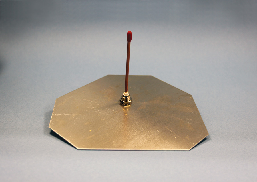
Now you have your choice of ground planes. The classic is just an aluminum plate with at least four dimensions of the plate 3.0 inches away from the center of the connector mounting hole. Figure 1 shows the antenna mounted onto a cattywampus plate with no particular shape or form. I did this to demonstrate that you can make the plate any size or shape you choose, just so long as there are at least four places where the ground plane is 3 inches long and roughly in the shape of a cross (+).
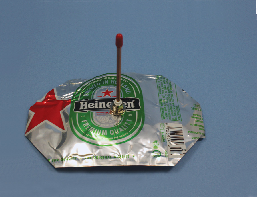
It is not necessary to use thick aluminum plate. Figure 2 shows the use of a very thin aluminum ground plane manufactured from stock found in nearly every shop building an Experimental aircraft. Note the raggedy edges and non-symmetric shape. One note is that any voice received by this antenna will have a strong Dutch accent.
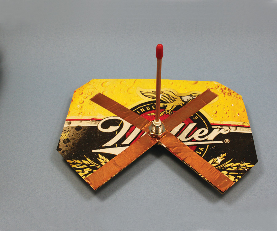
Similarly, the “plate” can be cardboard with metal strips (copper is best, but aluminum foil will do quite nicely) glued to the cardboard, as shown in Figure 3. I cut out one side of the cardboard to demonstrate that the cardboard is only there for structure and has no bearing on the electrical performance. Signals received on this antenna will have a Wisconsin accent—ja, you betcha.
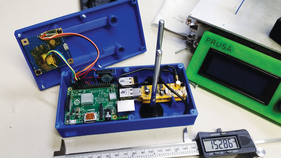
Figure 4 shows Tony Kirk’s (RV-6A at KDUH) homebrew “Stratux” ADS-B receiver. Tony has taken the leap that the data sent by the FAA ADS ground transmitters on 978 MHz are only repeating information sent down by the ADS transponder on 1090 MHz, so he built a 2-channel ADS receiver, one tuned to 978 and one tuned to 1090, so that he could get both data streams at the same time. In this image, the Raspberry Pi computer is the green board to the left, the GPS receiver for his aircraft’s location and altitude is the little square board bolted to the cover, and the two receiver module dongles are the brown boards stacked one on top of the other on the left in the blue box. This is really a homebrew project, as Tony is building these plastic cases using his own design and a 3-D printer for fabrication.
The antennas that most folks are using, unfortunately, are the silver rods you see sticking up out of the right side of the blue box. They are the collapsible antenna rods out of an AM-FM receiver and don’t do particularly well at microwave frequencies. They aren’t quarter-wave and they have no ground plane to work against, but they “seem to work well.” I think they would work much better tuned and with a ground plane, and be smaller to boot.
Now, a Weir Two-Fer. Since one of the antennas needs to be resonant at 978 MHz, and the other one needs to be resonant at 1090 MHz, we can get the 1090 antenna easily as above with a 2.5-inch long radiating rod and ground plane dimensions of 2.7 inches from antenna center.
Oh, bingo. Brian Anderson (Pulsar XP [registration ZK-PXB] in New Zealand) challenged me to build a simple, cheap transponder antenna. Since 1090 is the transponder frequency, whether you use it for ADS or regular transponder makes not a bit of difference. So now not only do you have an ADS antenna, you have a cheap transponder antenna for “regular transponder” use until 2020.
How’s that for simple homebrew antenna? Oh, and if you send me a case of either the thin metal raw material in its original packaging or a full case of the cardboard liquids, I’ll be happy to send you back the drained materials.
See you next month…stay tuned.

![]()
Jim Weir is the chief avioniker at RST Engineering. He answers avionics questions in the Maintenance Bay forum at pilotsofamerica.com. His wife, Cyndi Weir, was his high school sweetheart 50 years ago and now she keeps Jim from making stupid blunders in spelling and grammar. Check out rst-engr.com/kitplanes for previous articles and supplements.


