Neighbor Phil Hooper’s Velocity RG project is making serious progress. With the installation of the canard, it’s now almost a complete airplane (sans engine, interior, instruments, etc.)!
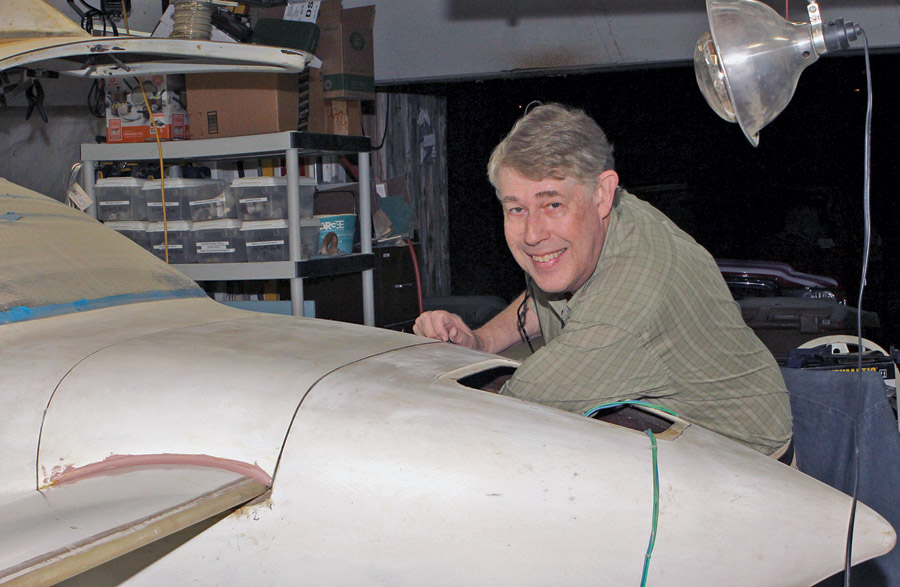
Phil Hooper beaming with pride after the successful fitting of the canard attachments on his Velocity RG.
The canard main anchors are two hardpoints in the forward bulkhead. It’s up to the builder to position the canard, mark and drill the pilot holes, then epoxy the mounting bushings in place. It sounds simple, but it’s a critical step that should not be messed up! The canard has to be centered, leveled, and the angle of incidence set. Using a plethora of tools, including a laser, tape measure, protractor jig, and a bubble level to check and recheck the position of the canard, Phil was ready to mark and drill the pilot holes for the bushing. Only one problem: There wasn’t room to drill the pilot holes owing to the proximity of the walls of the ever-narrowing nose cone. Even with a stub bit in a right-angle, close-quarter drill, we could not get lined-up square to the bulkhead. One option was to drill a small pilot hole at an angle, then drill the hole from the cockpit side, correcting for the angle and hoping to get in the ballpark. Ballpark might be fine for a home repair, but for a flying machine, it’s not good enough.
That holes needed to be drilled from the cockpit side of the bulkhead was clear. How to do this was a head scratcher. Measuring and marking were considered, but the top of the bulkhead was the only reference plane; all the other surfaces in the vicinity were curved. The solution: a drill guide.
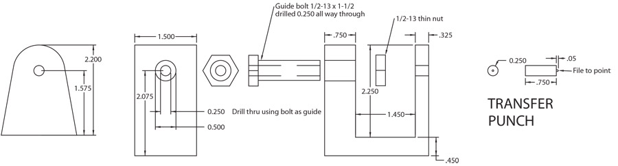
Drill guide frame, guide bushing, fixing nut and transfer punch.
Drill guides are common tools for metal airplanes. They are available commercially as strap duplicators or hole locators, but the concept is the same: You line up a dimple in the tool with an existing hole on one side (usually hidden) and, with the sheet to be drilled or dimpled in place, you bring the tool faces together and mark or drill the part.
In the case of Phil’s Velocity, the bulkhead is more than an inch thick, so a locator for sheet metal wouldn’t work. That meant a trip to my home shop to whip out a drill guide. The design parameters: Keep it simple.
The tool consists of four parts (or three if, as I explain later, you thread the hole for the guide bushing): The frame, the guide bushing and fixing nut, and the stubby transfer punch.

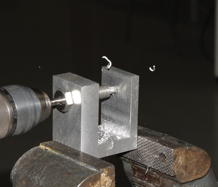
Fly-cutting to true up the blank.
The frame was made from a block of aluminum that was bandsawed and then fly-cut to square up the sides. The area for the opening was scribed using a height gauge, then roughed out on the bandsaw. The notch was cleaned up on the vertical milling machine using a long-reach (2 inches), two-flute, -inch end mill. If you have a 3+ hp milling machine, you can skip the bandsaw and hog out the material on the mill with a few passes. But my milling machine is less than 1 hp, so that meant light passes and slow feeds.
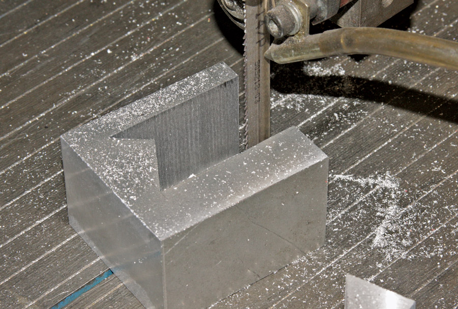
Using the bandsaw to rough out the frame.
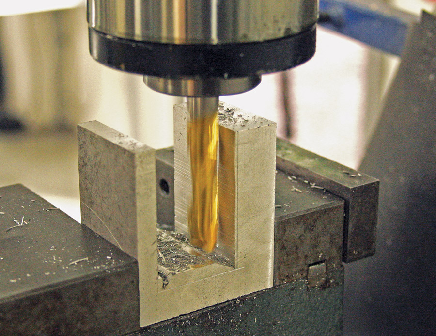
Using a long-reach end-mill and light passes to clean up the sides and bottom. Note the scribe lines.
With the notch complete, I marked and drilled the -inch hole for the guide bushing. Alternately you could drill and tap this hole for the bolt used for the guide bushing. In retrospect, I wish I had tapped the hole, as it would have made clamping the guide in place a little easier.
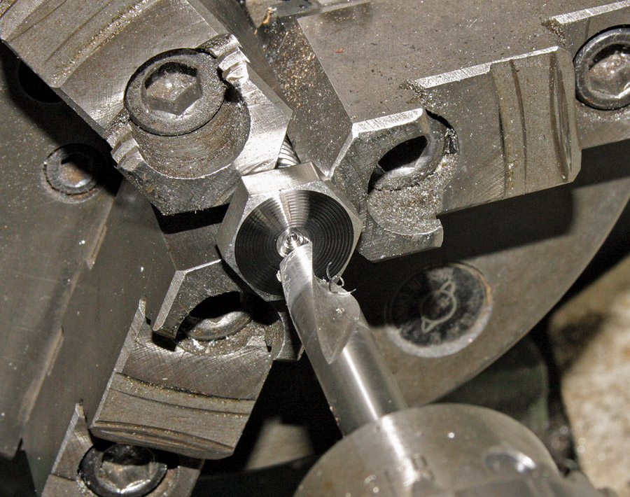
Facing and spot drilling the stainless bolt.
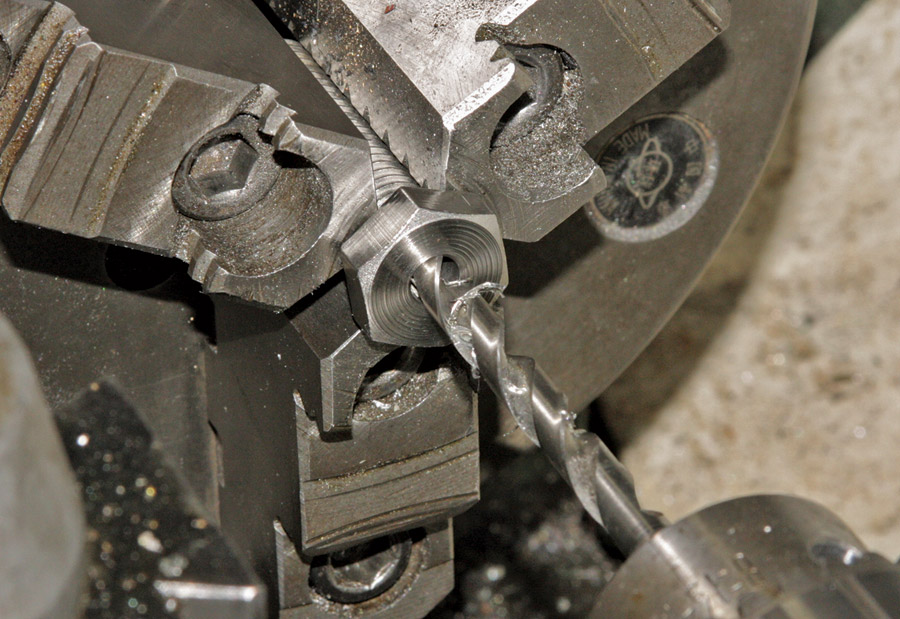
Drilling the -inch guide hole.
The guide bushing is nothing more than a -inch stainless steel bolt with a -inch hole drilled down the center. This is easy work on the lathe. Like most bolts, our example had embossed markings on the top. I faced these markings off and then spot-drilled the center. The through hole was peck-drilled 0.1 inch at a time, with cutting oil to prevent overheating. Pecking (retracting the drill to keep the chips from clogging) also helps prevent the drill from wandering off line. You’ll note in the photos that I used the 3-jaw chuck. There’s a slight risk to damaging the threads when drilling or turning a bolt this way. The trick is to tighten the chuck firmly enough to clamp the part and keep it from slipping, but not enough to ding the threads.
Drilling the “transfer” hole.
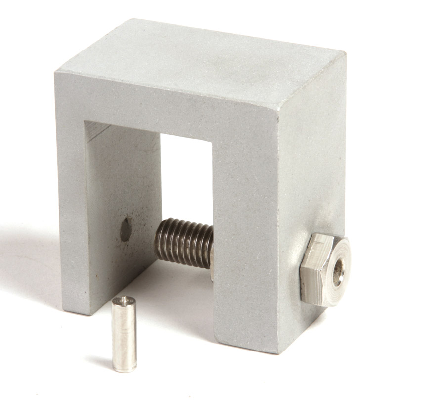
The finished drill guide ready for service.
I turned down a 3/8-inch stainless steel bolt to make the stubby transfer punch. The final operation was to install the guide bushing in the frame, clamp the bushing tight with the jam nut, and using a hand drill, make the -inch through hole in the frame. I deburred all the edges and then sandblasted the frame to obliterate the machining marks. With the addition of a coat of clear acrylic, our tool has a “factory” look to it!
With the canard clamped in place (leveled, centered, inclined, etc.), both hole locations are center-punched through the mounting tabs using the stub-length -inch transfer punch we made. It’s important to get a good punch mark because we’re also using that punch mark—and the punch—to locate the guide.
To help distinguish them on the rough texture of the composite skin, the punch marks were circled and a vertical reference line drawn with felt tip pen. The drill guide was then positioned using the transfer punch to find the dimple mark and clamped in place. Once we visually confirmed the guide was centered (Phil used a small mirror), we drilled the hole.
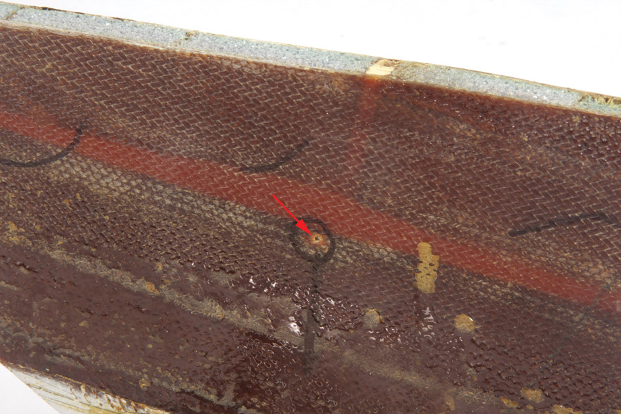
The punch mark indicating the correct location to drill (red arrow).
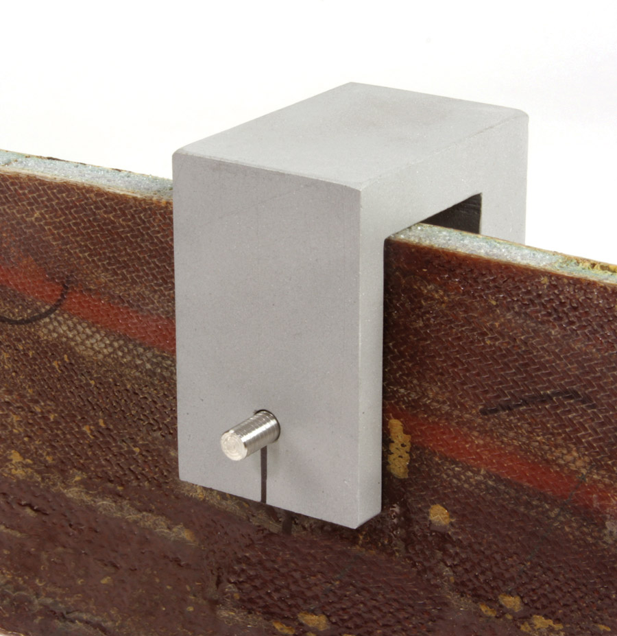
The punch mark and punch used to align the frame.

The guide clamped in place for drilling. (Note: these photo examples are illustrative and not the actual airplane.)
The guide worked like a charm. The canard tabs lined right up with the mounting holes and made the next step of adding the hardpoints a cinch.

Drilling the Velocity bulkhead for the canard mounts. The upper edge of the bulkhead has about a -inch overhang toward the cockpit side. The drill guide made all the difference getting the holes to line-up with the mounting tabs.
This may seem like a lot of work to drill two holes! But it really wasn’t, considering the amount of time Phil Hooper and builder-buddy Robert Rice had spent getting the canard in position. It had taken the better part of three work sessions measuring, adjusting, test clamping, leveling, and so on to get it right. The last thing they wanted was to mis-drill the tabs and have a big repair job on their hands. As for the tool, it’s a one-and-done item, at least for Phil’s Velocity. He’s often mentioned how much help he gets from the Velocity community, so in classic pay-it-forward style, the drill guide will be made available to anyone building a Velocity. Send an e-mail to [email protected] with Bob Hadley and Velocity Drill Guide in the subject line, and we’ll arrange everything.


