Last month we addressed motor oil as used in aviation engines; this month we’ll detail the mechanical systems that store, pump, filter and cool the oil.
Wet Sumps: The Motor Oil Swimming Pool
Most common Continental and Lycoming aviation engine oiling systems are simple wet sump designs very similar to your car’s engine. A reservoir of oil puddles in the sump (oil pan or intake in Lycoming-speak) located at the bottom of the engine. A gear-driven oil pump sucks oil from the sump through a tube or cast-in passages known as the oil pump pickup. A suction screen in this tubing protects the oil pump from ingesting boulders fallen into the oil sump, namely chipped gears, excess casting flash, wear metal, or hardware lost into the sump by the mechanic during cylinder changes or whatever. The oil pump uses a single pair of toothed gears to suck the oil from the sump and push it through the oil filter, oil cooler, engine, and to supply the prop governor if so equipped. The oil pump is driven from the engine’s accessory section gear train, which is, of course, driven by the crankshaft.
In the engine, two main oil passages—galleys—run the length of the engine and serve as oil freeways. Side passages from the main galleys feed oil to the crankshaft main bearings, the camshaft bearings, and via the hollow rocker arm pushrod tubes, out to the cylinder heads to the rocker arm bushings. Oil squirting out of the rocker arm bushings “splash” cools and lubricates the valve springs and valve stems.
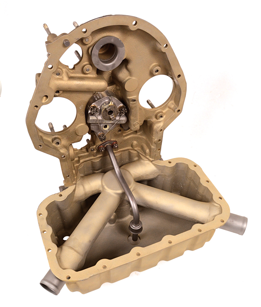
Mocking up the sump and accessory cover of an O-320 Lycoming serves as an excellent illustration of the typical wet-sump aviation oiling system. The oil pump is the silver unit with safety-wired nuts in the center of the upright accessory section; the oil pump pick-up tube is below the pump and drops into the oil sump. The four large tubes in the sump are intake manifold runners.
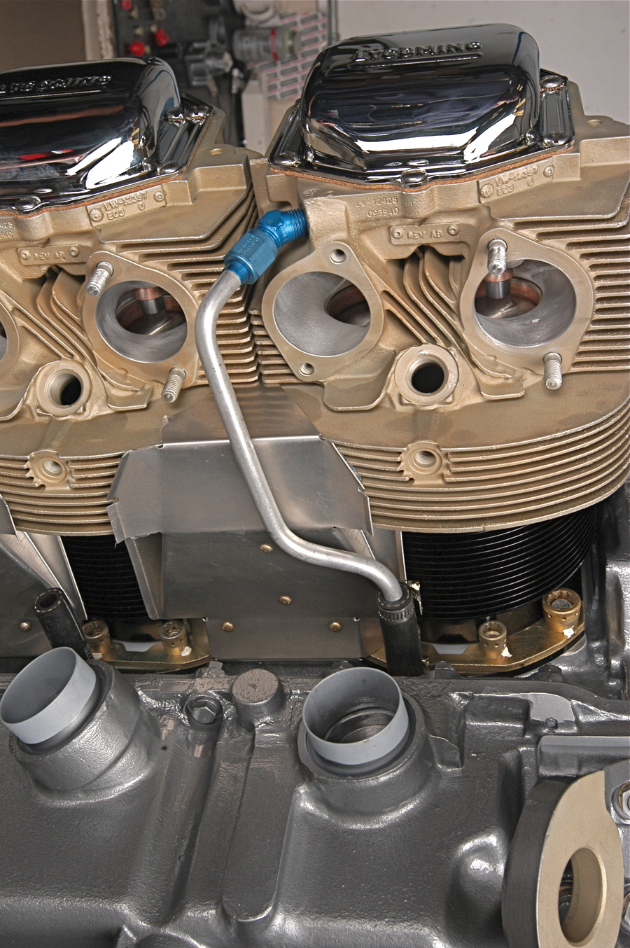
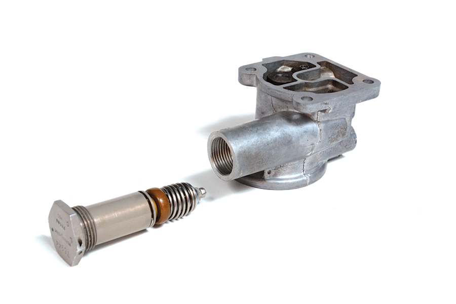
All 360 Lycomings, including this front-facing fuel servo application, dispense with the 320’s separate oil pump pickup pipe and use cast-in passages instead. It means fewer parts and more room in the crankcase for other things—such as a longer stroke crankshaft.
The rod bearings are oiled from the main bearings via passages drilled into the crankshaft; excess oil at the main bearings therefore travels to the rod bearings. As the oil squeezes out the ends of the rod bearings, it is flung everywhere inside of the crankcase and onto the cylinder walls. This splash oil provides the lube between the highly loaded camshaft lobes and valve lifters (tappets) and lubes the piston-to-cylinder interface, along with the piston pin-to-piston pin boss assembly.
In higher performance engines, extra piston cooling is provided by special passages in the case squirting oil directly onto the bottom of the pistons.
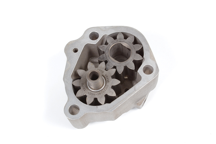
Two gears in a housing are the essence of the typical wet-sump aviation oil pump. Gear rotation sucks the oil from the sump on one side of the gears and pushes the oil through the engine on the other side. Scoring from debris wears the gears and the housing, costing oil pressure and flow as the clearances open up. This current style gearset uses one nitrited gear (“N” visible on one tooth) and one carburized impeller (“C” too faint to see here). Gear materials or finishes are purposely mismatched to reduce wear between them.
Oil extruding from the back of the rear camshaft and main bearings, along with some pressure oiling from the main oil galleys to the magneto drives, provides the splash lubrication in the accessory section to lube the gear train that powers the magnetos, vacuum pump, and so on. At the other end of the engine, oil is also sent to the propeller governor, which is itself part high-pressure oil pump and part speed governor. The oil pump in the governor jacks the oil pressure into the 300 psi range, then routes the oil through the front section of the crankshaft to the propeller where it powers a piston that controls propeller pitch. If a fixed-pitch prop is used, the prop governor is deleted and a plug seals the end of the crankshaft.
Oil returns to the sump via gravity. Dedicated oil drain-back tubes (Lycoming) or the pushrod tubes (Continental) provide both the return oil path to the sump and the necessary internal engine breathing (movement of the air/oil mist found everywhere inside the engine).
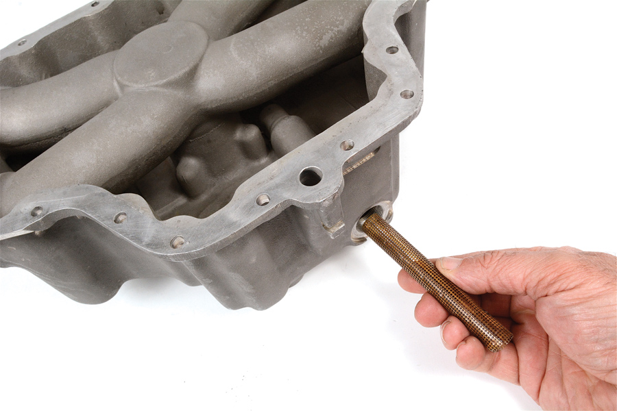
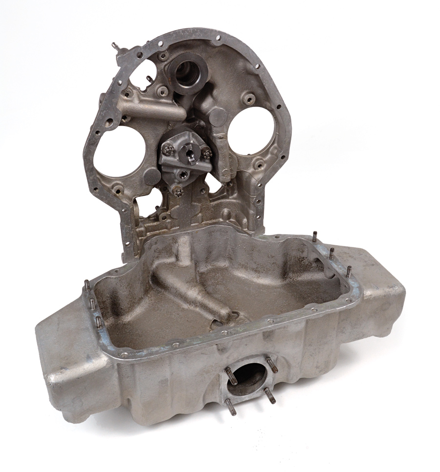
Suction screens on O-320 Lycomings are vertically mounted at the end of the oil pump pickup tube and are accessed from the bottom of the sump. On the O-360 shown here, the suction screen is horizontally mounted and lives behind a plug at the rear of the oil sump. The larger hole, just above the screen on the sump mounting flange, is the oil pickup passage where it communicates with the accessory housing.
There are some take-away concepts associated with the basic oil system. In no particular order: Relatively little of the oil is found at the working points (bearings, bushings, piston rings) at any given moment; most of the oil is found “resting” in the oil sump. There’s voluminous oil mist whipping around inside the engine. This windage produces drag on the rotating crankshaft and connecting rods. The piston and piston pin are direct witnesses to combustion heat, but their only heat rejection path is through the oil. That junk that ends up in the oil gets spread all through the engine unless filtered out. The connecting rod bearings are oiled downstream of the main bearings; if oil volume drops, the rod bearings will be the first to know. A standard wet sump only works when upright or in positive-G flight; rolling the airplane upside down for sustained periods or going straight up or down means the oil pump cannot reach a supply of oil to pump.
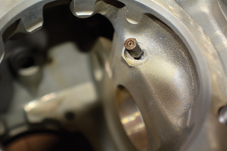
Angle-valve and parallel-valve Lycomings with turbochargers come stock with piston squirter valves for increased piston cooling. The squirters thread into a crankshaft bulkhead so their spray hits the piston underside near mid-stroke. They definitely work; engines retrofitted with them need a larger oil cooler to maintain the same oil temperatures. A tiny ball-and-spring valve inside the squirter nozzle closes oil flow at low oil pressure to avoid excessively lowering oil pressure at idle. Continentals use a small pipe with no valve for the same job.
Dry Sumps
A more sophisticated (expensive, heavy, complex) oiling system is the dry sump. Dry sump systems employ multiple—at least two—oil pumps. One of these pumps is similar to a wet sump pump in that it supplies oil under pressure to the consumers inside the engine. The other oil pump(s) are scavenge pumps; they suck oil from the sump (and wherever else oil might puddle, such as from the valve covers or accessory section). These scavenge pumps are running all the time, and instead of letting the oil gather in a sump, the oil is scavenged immediately to an oil tank outside of the engine. The pressure oil pump is fed from the oil tank and oils the engine exactly as the oil pump does in a wet sump engine.
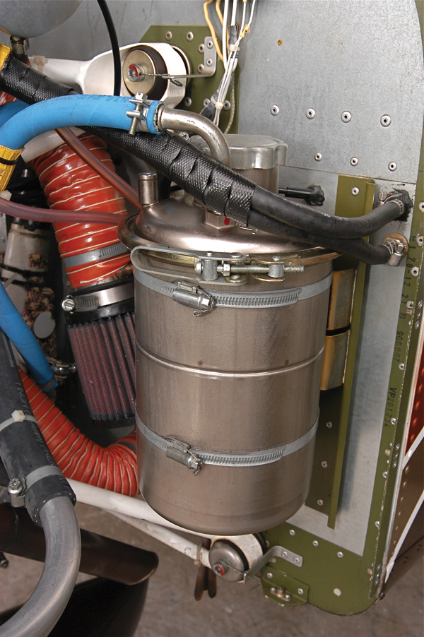
Rotax engines are dry-sumped and therefore store their oil in a vertically mounted round tank separate from the engine. Oil enters the tank on a line tangent to the outer wall. This swirls the oil to deaerate and cool it.
Dry sumping offers powerful advantages. For starters, much more oil can be carried in the oil tank without creating excessive windage. This means fewer hot trips through the engine for any given drop of oil, so the oil inherently runs cooler and does not get as dirty as fast. Given a flop tube inside the oil tank, the oil supply pump always has a ready oil supply no matter the aircraft’s orientation to gravity, although in practice most engines still oil best upright. Also important, the scavenge pumps suck the windage from the crankcase, thus releasing power otherwise wasted on rotating the crankshaft assembly through a thick oil mist. Piston ring sealing is also more positive due to the negative crankcase pressure. The oil sump or pan can be smaller because it need not hold an appreciable volume of oil. This makes the engine a little slimmer and can facilitate a smaller airframe frontal area.
Dry sumping has traditionally been too expensive for Lycomings and modern Continentals. Rotaxes use it as a matter of course, as do helicopter Lyc’s and Continentals, plus radials, and the WW-II V-12s. Furthermore, our low-rpm engines don’t waste too much power on windage losses, so the efficiency gain to dry sumping is limited on a run-of-the mill general aviation engine.
Inverted Oiling
With the postwar popularity of aerobatics, an add-on inverted oil system was needed to help conventional wet sump engines when turned upside down. When that happens, oil flow and pressure is lost immediately because the oil pump pickup draws only windage from the sump because the liquid oil is now puddling at the “top” of the crankcase. Even better (worse?), oil pours out the breather.
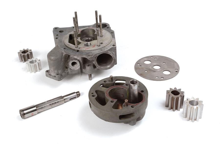
Piston-powered helicopters mount their engines vertically, with the accessory case down. This requires dry sumping and a two-stage (one scavenge, one pressure) oil pump. As this exploded view illustrates, a dry-sump pump is typically two oil pumps in one housing separated by a plate.
For Lycomings, the popular Christen system was the result. An add-on system external to the host engine, it provides an additional oil drain back from somewhere on the top of the engine (typically the stock breather location atop the accessory case), plus a two-way valve using a pair of heavy ball bearings free to slide in a tubular passage, along with an oil separator tank that also contains a gravity-driven ball valve. As the airplane rolls inverted, the ball bearings in the 2-way valve seal off the upright oil pickup and open the inverted pickup, while the ball valve in the separator tank keeps liquid oil from running out the breather. The oil pump is thus supplied during sustained inverted or negative-G maneuvers. Such systems really don’t do much in downward vertical or sustained sideways (knife edge) flight. They also port a negligible amount of oil into the separator tank with each transition from upright to inverted flight. That said, such systems are a huge oiling improvement to some hapless Lycoming tasked with powering a Pitts through an outside loop.
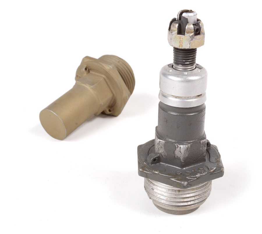
Oil pressure regulators are all simple spring-and-ball valves that open at a set oil pressure. Early regulators lived under the closed end cap at left and were disassembled for adjustment. For years, the externally adjustable style with the castellated nut has been stock. It’s much more convenient to adjust.
Pumps, Filters and Things
With that overview of the three common lubrication systems, let’s more closely examine a few oiling subsystems and parts, starting with the oil pump. Considering they’re bathed in oil, you’d think these things would last forever, but they merely live a long time. Eventually clearances open up where the gears rub on the pump body, and the gears themselves sometimes pit and wear so much you’d swear they were processing gravel. Pumping efficiency is reduced by the larger clearances, so expect to replace the pump during a major overhaul. Also, back in the mid 1990s, there were Airworthiness Directives on Lycoming oil pumps to replace sintered iron and aluminum gear sets; this is an excellent AD to keep current on.
Remember that while oil pressure is necessary, the volume of oil flow—typically a Niagara-like 7 to 12 gallons per minute—is even more critical.
Oil Pressure Relief Valve: Because oil pressure varies with temperature, rpm, bearing wear, and modifications to the oiling system (larger oil coolers or adding hose length and hose fittings lowers oil pressure), there is a need to regulate oil pressure. Also, to provide a safety margin and accommodate field modifications, oil pumps are typically of much greater capacity than normal operation demands. All this means is an oil pressure relief valve is provided. A simple spring-loaded ball-and-seat valve, the pressure relief valve opens when pressure rises too high, venting some oil flow back to the crankcase.
The oil pressure relief valve is adjustable. On earlier models this is via shimming the spring, changing to a different rate spring, or both. Later valves—and a host of aftermarket valves—fit a screw-adjustable mechanism to speed the process.
Lycoming’s oil pressure recommendations are typically between 65 and 85 psi at cruise rpm, and at least 25 psi at hot idle. Given the low engine rpm, this is higher pressure than your car because in aviation, the crankshaft bearing areas are vastly larger, so there is a need to flow generous volumes of oil for cooling, plus a necessity of overpowering G loads in accelerated flight.
Minimum oil temperature is controlled by the Vernatherm, shown here with the oil filter adapter it is often threaded into. The Vernatherm expands with heat; at its set point it expands to close off the passage bypassing the oil cooler, thus shuttling hot oil through the cooler.
Oil Thermostat: Oil temperature is regulated by a thermostat, most often referred to as the Vernatherm after its manufacturer. Typically these are set to close at 180-185F, at which point oil is directed to the oil cooler. Oil flow to the cooler is controlled because cold oil doesn’t lubricate well, and the oil cooler can be harmed or burst by the high oil pressures generated by cold oil.
Oil cooling systems must be sized to accommodate the hottest expected temperatures, such as high-power settings in summertime. Naturally, this is too much cooling for low-power winter cruising, even with the Vernatherm open. Thus it may be necessary to blank some of the air flow to the oil cooler with a plate in winter.
Filtration: For some reason oil filtration seems a great subject to start fights over, but the basics are pretty simple. The old oil screen system is lousy, catching only about 60% of junk 80 microns or larger. Common aviation spin-on oil filters snag more like 35 micron debris, so a filter offers an immense oil-cleaning improvement over a screen. Some sources say nine times better filtering! Older engines not yet retrofitted with an oil filter really ought to be. If you want more convincing, oil change interval specifications rise from 25 hours to 50 hours when moving from a screen to a filter.

Compare the filtering area of the pleated paper element inside the oil filter at right to the simple oil screen at left—it’s not even close! The old school screen lives in the canister-like casting at left in the background.
We’ll also say some aftermarket oil filters are advertised on their merit to filter down to single digit micron levels. This is great, but does reduce oil flow volume while not addressing lead and sludge contamination, so oil change intervals cannot rise with them. Also, not all oil is filtered all the time because the oil filter mount is provided with a spring-loaded bypass valve (additional to the main oil bypass valve that sets overall system pressure). Cold oil is too viscous to pass through the oil filter, so the bypass opens until the oil pressure drops; very fine filters mean this bypass valve would remain open considerably longer, defeating the purpose of finer filtration.
Next month we’ll examine engine cooling.
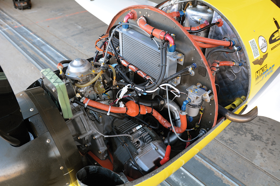
Never forget the oiling system is also a major part of the engine’s cooling. This two-cylinder Hirth exemplifies this maxim via a disproportionately large oil cooler. It’s necessary because the Hirth oil cools the upper cylinder head and has a gear reduction prop drive.


