In our discussion of propellers so far, we have covered basic momentum theory and taken a look at the characteristics of the incident airflow on the blades. We now turn our attention to some more details of the shape of the blades themselves.
Like a wing, a propeller blade is characterized by its area, planform, and airfoil cross section. As we have seen in previous months, the airflow conditions along the length of the blade vary in a much different way than on a wing. Accordingly, the airfoil and planform choices for a good propeller are different than those for a good wing.
Diameter Limits
For most airplanes the propeller diameter is set primarily by a combination of tip Mach number and landing gear length considerations. On a direct-drive engine, the full-power rpm is set by the engine characteristics, and this in turn limits the diameter of the propeller. If the engine is geared, the designer can adjust propeller rpm, as well as diameter, to get to an optimum design point. Tip Mach number becomes less of a limit because the prop rpm can be chosen to keep it at an acceptable value, and ground clearance and propeller weight start to become more important limiting factors.
For extremely large propellers, blade structural considerations, both strength and stiffness, can limit the maximum feasible diameter as well.
Once the diameter of the propeller is set, the designer must come up with a blade design that will absorb the power of the engine at the proper rpm and convert it to thrust as efficiently as possible. The parameters available to achieve this are blade area, blade airfoil, blade planform, number of blades, and pitch.
Solidity
The blades must have enough area and pitch to absorb the power delivered by the engine at the right rpm. Increasing either blade area or blade pitch increases the amount of power the propeller will absorb, so proper design involves finding the proper balance between area and pitch. If the blades have too much area, the parasite drag of the blades will hurt efficiency. If they are too small, they may stall before the pitch reaches a high enough value to absorb the power of the engine.
The solidity of a propeller is the ratio of the blade area to the area of the disk swept by the propeller. A high-solidity propeller has a large blade area relative to its disk area. Theoretically, increasing solidity decreases efficiency because the blade parasite losses increase with increasing blade area. In practice, this is only true if the designer has the option of choosing the theoretically ideal propeller diameter to absorb the power of the engine. As we have seen, the diameter of the propeller is often limited by other factors to a lower-than-optimal size.
Since most light airplane engines turn at about the same speed, we can see that the maximum propeller diameter hits a practical limit very quickly. As power increases, it becomes necessary to increase blade area and propeller solidity to absorb the power in the diameter allowed.
Up to a point, increasing blade chord works well. If the blade chord gets too large, several problems appear. The blades get heavy, and the structural issues of joining a large blade chord to a practical shank and hub get severe. At this point, increasing the solidity and total blade area of the propeller by increasing the number of blades is a better design option than increasing the chord of a smaller number of blades.
As we see on some modern turboprops, when the power gets large, a high-solidity prop with many blades is often the best solution.
NACA did many tests on propellers to determine the effects of diameter, solidity, and number of blades on propeller performance. One of the best references on this subject is NACA Technical Report 640, published in 1938. This is available online at the NASA Technical Reports Server.
Blade Planform
Ideally, we want every element of the propeller blade to be flying as efficiently as possible. The way to do this is to design the area, taper, and twist of the blades so that at every point along the blade, the blade element is operating at the lift coefficient at which the blade airfoil develops its highest lift-to-drag ratio (L/D). It is this ideal blade lift coefficient that determines the optimum blade area.
Chord Variation Along the Blade
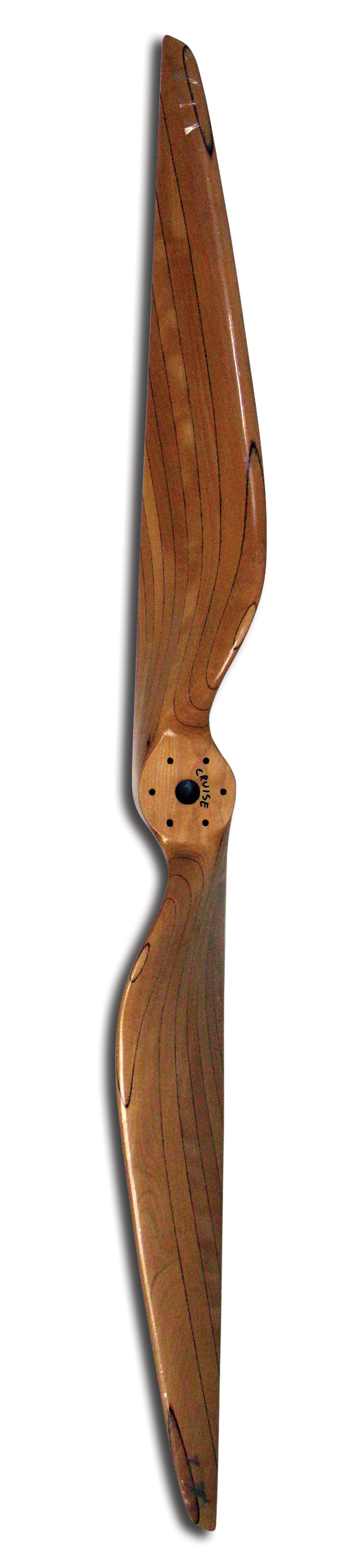
Looking at the airspeed of the elements of the blades as a function of the distance from the hub, we can see immediately that an efficient propeller will have a significant amount of taper in the blades. The tangential component (due to prop rotation) of the velocity of a blade element increases linearly as we go outboard on the blade. The dynamic pressure of the air increases as velocity squared.
If the blades had a constant chord, the lift on the blades would increase roughly as the square of the distance from the hub if the blade elements were all operating at the same lift coefficient. This would make the prop excessively tip-loaded. The loading on the blade can be adjusted using twist, but this would cause the outboard part of the prop to be operating at a much lower lift coefficient than the inboard portion. Only a small part of the propeller would be at the optimal lift coefficient for the blade airfoil, and the parasite losses due to blade element drag would be increased over the optimum.
The solution to this is to vary the chord of the blade over its span. By adjusting the local chord, each blade element can be operating at or near its optimum lift coefficient while producing the right amount of thrust to give an efficient spanwise loading of the blade.
The ideal loading on a propeller changes with advance ratio because the variation of incident angle of the airflow along the blade is a function of advance ratio. The variation of blade element airspeed along the blade also changes with advance ratio.
Accordingly, there is no single “ideal” propeller blade planform. Each propeller must be designed to match a specific advance ratio and power input.
Figure 1 shows the variation of local airspeed along the blade of an example propeller flying at different airspeeds and constant rpm. Our example prop has a diameter of 72 inches and is operating at 2400 rpm.
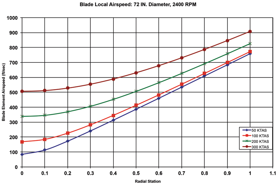
Note that at 50 knots forward airspeed (J=0.35), the airspeed at the tip is 7.5 times the speed at the 10% radial station. Increasing the speed to 300 knots (J=2.1) changes this significantly. The tip airspeed is now less than twice the airspeed at 10% radius.
At low advance ratios, the tangential velocity dominates. This causes a large variation in airspeed over the length of the blade. Props designed for low advance ratios accordingly tend to have very highly tapered blades.
At higher advance ratios, the forward velocity becomes more significant. This reduces the variation of airspeed over the length of the blade and makes the optimum planform somewhat less tapered.
Practical Considerations
The theoretically optimum planform for a propeller blade is often not practically buildable. Particularly for low advance-ratio propellers, the optimum blade planform has very large chords very near the root. It is difficult to get these large chords to integrate with a reasonable propeller hub design, so it is relatively common to see shorter than optimum chords on the inner portions of prop blades.
At the other end of the blade, extremely small chords in the outer portion of the blade may be theoretically efficient, but they are difficult to make strong and stiff enough to hold up in ordinary use. Also, extremely small tip chords may lead to a degradation in airfoil performance due to lowered Reynolds number.
The best physically realizable propeller will almost always be a compromise between the theoretically optimum and the practically buildable.
Airfoils
The airfoil cross-section of the blades also affects propeller performance. A well-designed propeller operates with the local lift coefficient of each blade element at the value for best L/D of its airfoil. Because of this, the operating lift coefficient of a propeller blade element is somewhat higher than the typical cruise lift coefficient for a light airplane wing. Accordingly, propeller airfoils tend to have more camber than wing airfoils for cross-country-capable airplanes.
Many propellers use the Clark Y or similar flat-bottomed airfoils with cambered upper surfaces. This was an appropriate choice for props with wooden blades, since the 12% thick Clark Y was thick enough to make structurally sound, stiff-enough blades. The problem with such sections is that they have relatively low critical Mach numbers, and accordingly limit the acceptable tip Mach number of the propeller.
One of the primary advantages of early metal propellers like the Curtiss-Reed props used on the Curtiss Racers was that the metal construction allowed the designers to make the airfoils of the propeller tips much thinner than was possible with wood. This allowed the props to operate efficiently at higher tip speeds, which in turn allowed either larger prop diameters for a given rpm, or higher rpm at constant diameter. The higher diameter increased prop efficiency, while the higher rpm allowed the engines to turn faster and develop more power.
On modern propellers, it is common to vary the airfoil along the span of the blades. Thicker sections are used inboard to improve the stiffness and strength of the blade, and thinner, less cambered sections are used outboard to allow the propeller to operate efficiently at a higher tip Mach number.


