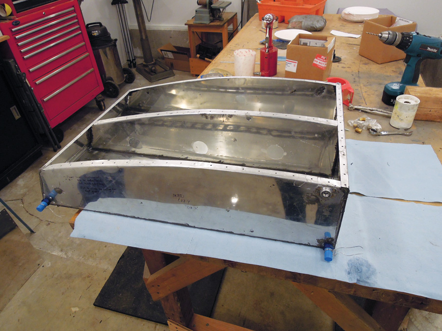
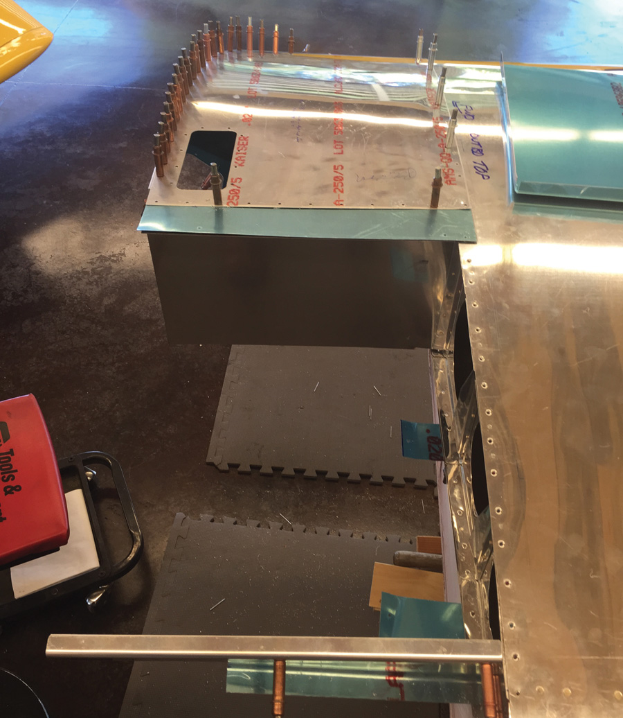
A riveted fuel tank ready for the top skin. The blue-capped fittings are outlets, and the upper fitting is part of the sight gauge that will be installed after the wing is installed.
As you might remember from the last exciting episode, the Pudding River Bearhawk crew was closing in—however slowly—on completing their Bearhawk LSA.
Well…remember how Charles Schultz’s cartoon dog Snoopy looks when he’s happy—feet flying, ears twirling as he dances with delight? Well, none of us exactly “twirl” anymore, but we can appreciate the emotion…because…
The wings are done!
Even as we were riveting up the skins on the second wing, we knew that there were still two major projects ahead before we could call the wings really done: fuel tanks and wingtips.
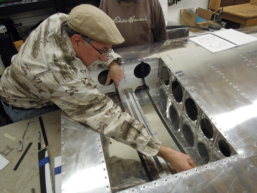
Rion fits one of the upper straps that suspend the fuel tank within the wing. Getting the exact length was tricky.
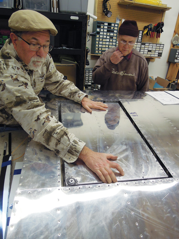
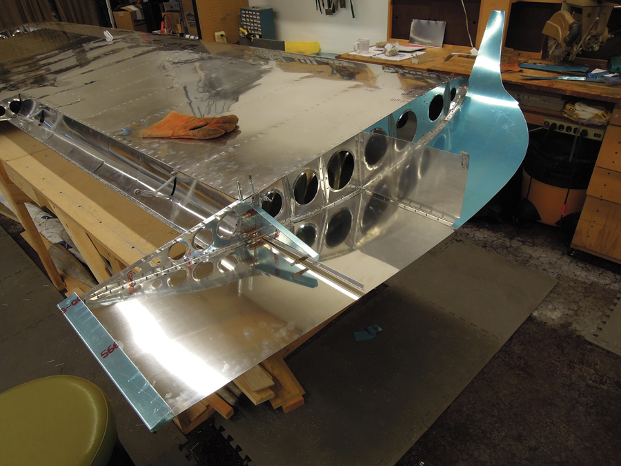
With the straps in place, the tank can be fitted into the wing.
Building the Tanks
The construction plans barely show the tanks and have no details at all of how they are built or installed, but the rudimentary construction booklet that came with them gave enough information to form a basic picture: The Bearhawk uses a 15-gallon tank in an inboard bay of each wing. They are suspended between the spars by steel straps, tensioned by adjustable clamps, and accessed by a removable panel of lower wingskin.
The “plans” call for them to be welded from formed bulkheads and skins made of 6061 aluminum—a weldable alloy—0.040-inch thick. We didn’t have a ready source of 6061 in .040—although it would have been possible to get some—and we certainly didn’t know how to weld aluminum. Between us, though, we’d built several tanks for RVs using the Van’s method of riveting with tank sealant between all the pieces. Even though we’d learned some lessons about departing from designer Bob Barrows’ plans—his methods usually worked better than ours!—a conversation with Barrows at Oshkosh let us know he had no objection to riveted/sealed tanks…he just preferred welding to messing with tank sealant. We decided to go with what we knew and build riveted tanks. Because they were separate, stand-alone structures, we figured if we got the strength and shape right, the construction method was secondary.

Tensioning “buckles” for the tank straps were made from bolts with the heads removed. One side is drilled and tapped for stainless steel Allen-head bolts.
In most RVs the tanks do double duty as the inboard section of the wing leading edge, so they are riveted with flush, solid rivets. In the Light Sport RV-12, though, the tank is a simple aluminum box riveted with sealant and blind rivets. The latter was the most similar to the Bearhawk tanks. Neither contribute to the shape or structure of the airframe—they are just containers strapped into the airplane for the sole purpose of holding fuel. We chose to copy RV-12 construction.
I made form blocks for the tank ribs and pounded out three per tank, using .032 Alclad 2024-T3. We bent skins on a simple brake, forming the top and front from one piece, the rear and bottom out of another. There’s nothing tricky about assembling the tanks—clamp the parts together, drill the hole patterns for the rivets that will hold them together, deburr and clean all the parts, apply tank sealant and blind rivet the “box” together, using the same closed-end blind rivets used in the RV-12 tank.
We installed two RV-10 fuel pickups in each tank, one at the forward corner and the other at the rear. I put them as close to the bottom skin of the tank as I could, but we suspect that testing will reveal at least a gallon of unusable fuel in each tank. The pickups are plumbed together just outside the tank with a single aluminum fuel line running to the selector valve. By having one forward and one aft, one should always be submerged in fuel, whatever the airplane’s attitude.
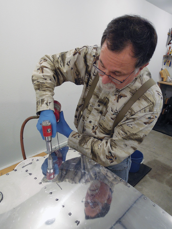
A pneumatic blind rivet gun makes short work of closing the tank.
A simple push drain was installed on the inboard aft corner of the tank and a hole cut in the access panel to let it protrude. The filler neck was located by strapping the tank in place and using a long drill bit to poke a hole through the top wingskin and tank. We cut the hole in the wingskin to 2.25 inches to accommodate the 2-inch filler neck—the strapping method isn’t precise, and we wanted a little wiggle room.
Although the construction booklet gave complete plans for making the multi-part vented gas caps on a metal lathe, we weren’t looking for ways to make the wings take longer and bought the pre-made caps from Bearhawk. They’re nicely made, fairly priced, and fit perfectly.
The most difficult part of tank building and installation, to our surprise, was nothing on the tank itself…rather it was the straps holding the tanks into the wings. We made these out of steel banding material used to hold shipping crates together, covered with shrink tube. The exact lengths of both the short and long sections of the straps turned out to be quite important, and there are no dimensions on the plans—actually, given the realities of scratch-built airplanes, it probably isn’t possible to give one. We figured it out through trial and error. Allen-head bolts threaded into drilled and tapped steel rods (simply large bolts with the heads and threads cut off) pulled the straps together and provided the tension to hold the tanks. These are buried between the rear of the tank and the rear spar of the wing and are difficult to reach. Way too much practice taking the tanks in and out finally led us to develop a technique that worked, but we hope we don’t find ourselves removing the tanks very often. If I’d made the tanks about -inch shorter, access would have been quite a bit easier.
With the tanks and fuel lines finally installed and buttoned up, we turned our attention to the last big project on the wings—the wingtips.
Building the Wingtips
Bearhawk wingtips are more or less left to the builder. The construction booklet suggests you could carve a wingtip out of blocks of foam glued to the end of the wing, cover that with fiberglass, finish that out to a smooth surface, make a fiberglass mold off the “positive” tip, and make the actual fiberglass tip in the “negative” mold. Nothing to it.
RV-12 parts were used as patterns for our all-metal wingtip.
In my long ago Malibu youth, I’d shaped and glassed several surfboards so carving and finishing the tip didn’t intimidate me…but I knew it would be messy (not a good thing in the TajMahangar with its polished floor) and tedious. Making a blank, pulling a mold, and making the part inside that seemed reasonable if we were going to be making several sets of tips, but it’s an awful lot of work for just one set. I just knew that if we made our tips this way we’d have four or five months of part-time work in one set of tips, and worse, that time would be spent working with fiberglass. Does anybody really like working with that? None of us do…so we looked for alternatives.
The best was right in front of us. Phillip recently had worked up a set of metal tips for his other project: a super-light RV-9A. Both the KK-1 and the RV-12 that I’d built earlier had used some cleverly shaped aluminum parts to form very light and aerodynamically clean tips with no compound curves. It helped that both those airplanes were designed on CAD systems, so the complicated metal shapes that bend into a graceful tip were accurately designed and manufactured. We decided to go for it, and build metal wingtips.
The RV-12 wing has almost exactly the same chord and thickness as the Bearhawk, so our first thought was, let’s just copy that. That didn’t work exactly, because the airfoil shapes are quite different. The Ribblet airfoil chosen for the Bearhawk LSA has a concave, cambered, lower surface, which complicates the shape of the tip.
The high-wing Bearhawk won’t have the rectangular handhold used on the RV-12. The flat top of the wingtip (right) was fairly simple, but the bottom was complicated by the airfoil shape.
We didn’t have a CAD system, so we bought a few parts of the RV-12 wingtips from Van’s and used them as disposable patterns, cutting them as necessary to fit the new shape. Phillip, with his engineering background and recent experience, was appointed geometer-in-chief, and using his eye, some basic math, and some cut-and-try pattern making, he came up with a five-piece wingtip that simply riveted together. We were able to use a couple of the RV-12 parts without alteration, which pleased us.
Phillip drills one of the five pieces making up the all-metal wingtip.
The geometry isn’t simple, and we were surprised how very small changes in almost any dimension made big changes in the final shape. Eventually, we burned through enough scrap aluminum and cardboard and arrived at a sleek flush-riveted wingtip that weighs less than a fiberglass unit, took a lot less time, and was much more fun to build. It gives a unique touch to our airplane.

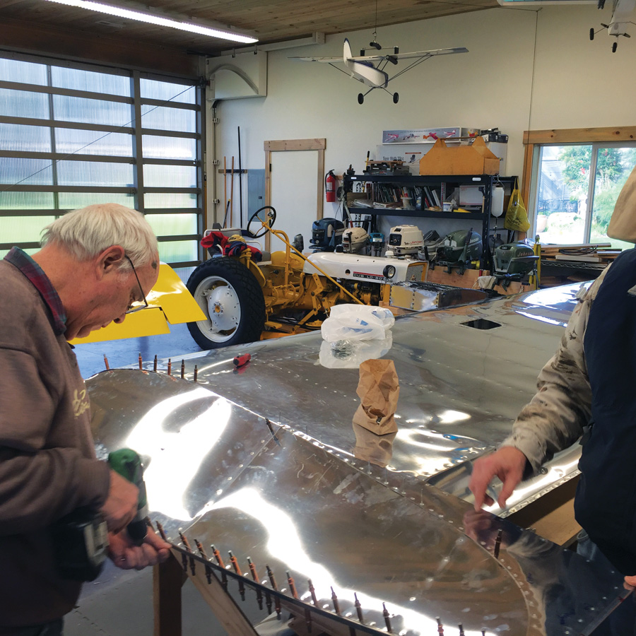
Rion sets up the blind rivets for the final installation of the wingtip.
When the last rivet went into the wingtip, we poured a glass of homebrew (brewing beer is a close second to aviation as an approved activity on our airpark!) and celebrated. The wings are done! In a phrase made famous in the Pacific Northwest by William Clark (during his expedition with Meriwether Lewis) 212 years ago:
O! the joy!
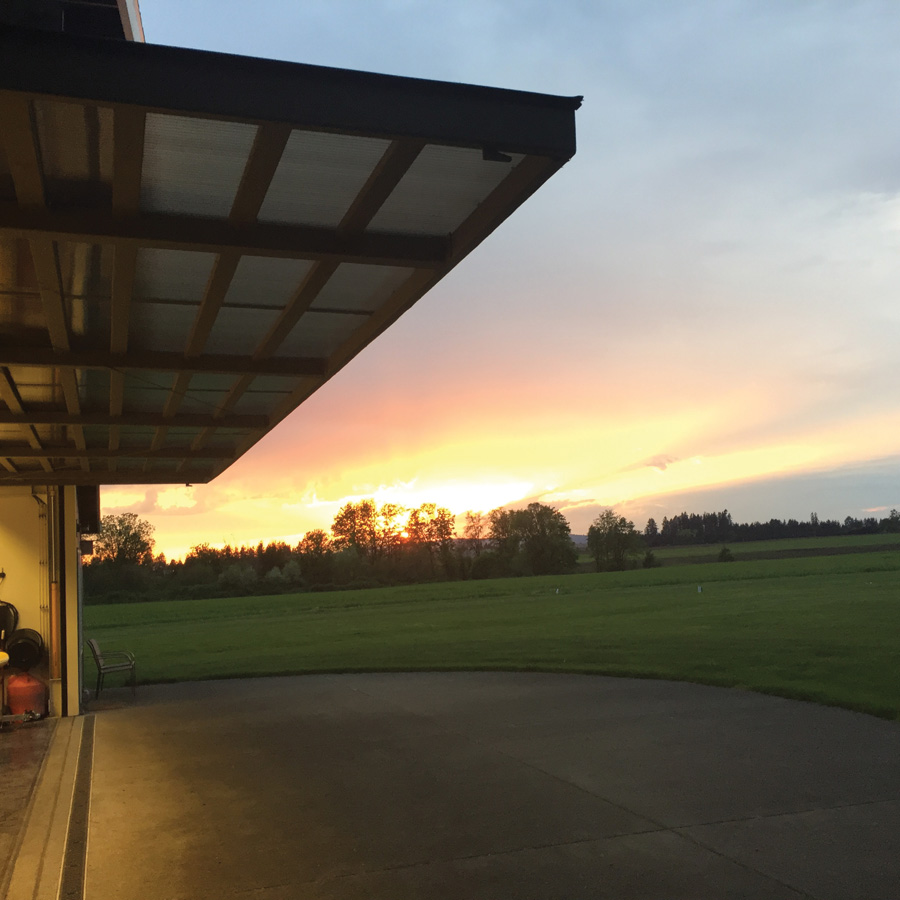
Some days you just have to set down the tools, step outside, and realize how lucky you are to live in a place like this.


