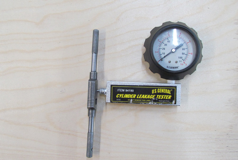
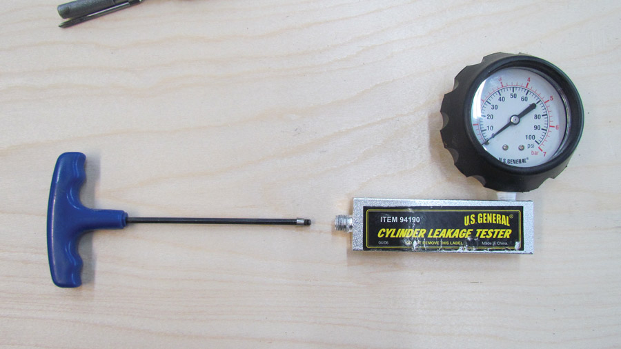
I bought a Harbor Freight compression tester, only to find out that it wasn’t designed to do the type of test required for aircraft engines. When I purchased it a few months ago, the U.S. General Cylinder Leakage Tester (Item #94190) was on sale for $21.95. However, that unit is no longer shown on the Harbor Freight website and appears to have been replaced by the Pittsburgh Cylinder Leak-Down Tester (Item #62595). Except for a black-and-yellow sticker on the gauge base and a black carrying case instead of red, the two units appear to be identical. Not on sale, the current price is $39.95.
When I tried to use the tester right out of the box, it didn’t work in the usual 80/xx mode required for aircraft engines. I disassembled the unit and found that it had a .080-inch orifice in it instead of the .040-inch orifice specified for aircraft engines with a bore of less than 5.00 inches or a .060-inch orifice for engines with bores of over 5.00 inches. The photos show a .040-inch orifice because I am flying behind a Jabiru with a bore of less than 5.00 inches.
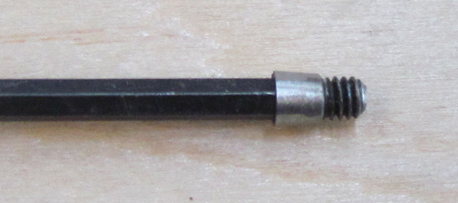
The .080 orifice in the gauge base was drilled out with a #36 drill bit, then tapped with a 6-32 tap. Next, a 6-32 socket head cap screw was cut off so that the distance from the bottom of the socket in the head to the end of the screw was .250 inches.

Make a new orifice from a 6-32 socket-head cap screw.
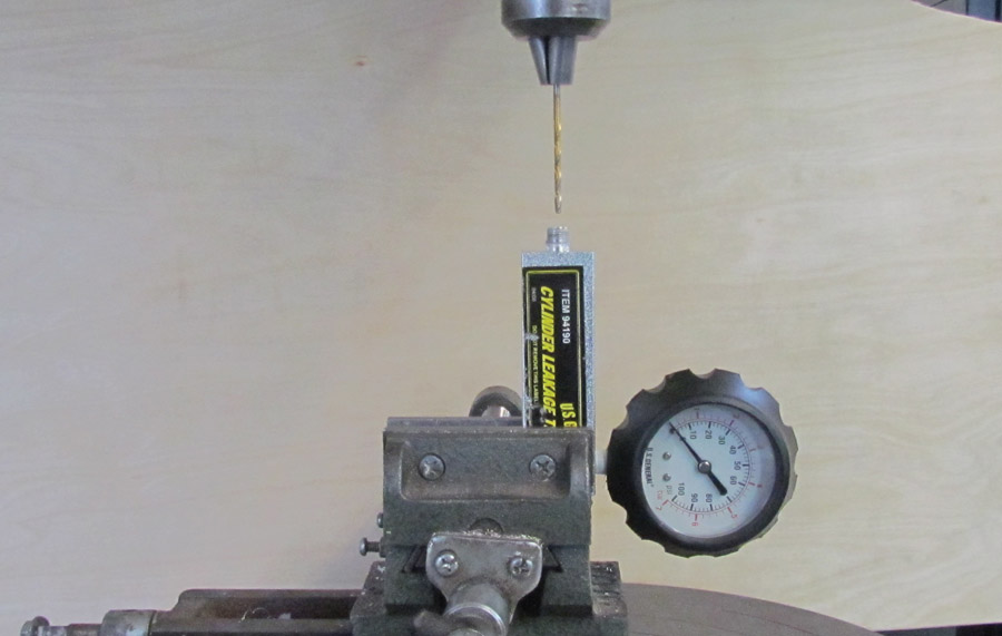
A .040-inch hole was drilled lengthwise through the screw. This is done most easily in a lathe, but if you’re careful, it can be done by hand with the screw held in a vise. The entrance and exit of the .040-inch hole were tapered with a larger drill bit that was ground to a 60-degree point angle.
The cap screw head was too large to fit into the orifice block, so the diameter was ground to fit. I did this on my 1-inch belt sander, or if you have access to a lathe, it can be turned to size.
Thread sealer was applied to the cap screw threads and the screw was inserted into the gauge base. Be careful to not get any thread paste or tape in the orifice.
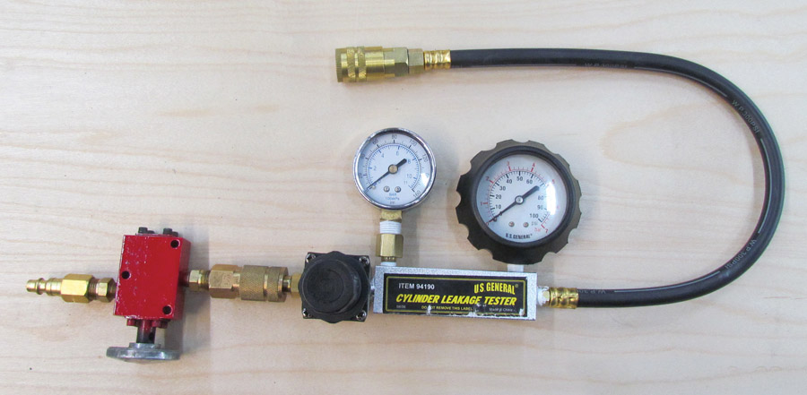
The leak-down gauge supplied by Harbor Freight must be replaced with a 0-100 psi range gauge. As shown in the photo, the supplied gauge has been moved to the cylinder-pressure side of the orifice. To make the tester easier to use, I added a shutoff valve on the air supply.
Drill out the .080-inch orifice in the gauge base using a #36 bit.
Tap the #36 hole using a 6-32 tap.

The gauge base after drilling and tapping.
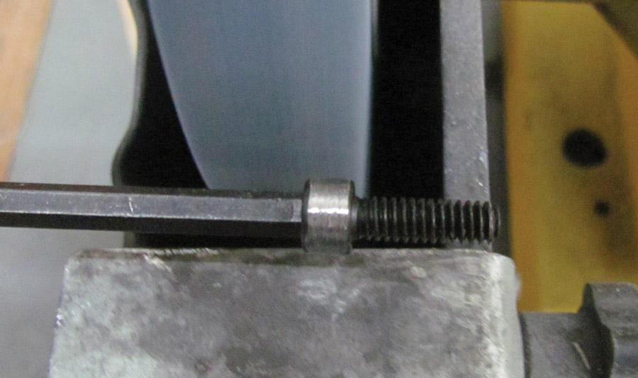
Grind the cap screw to the correct diameter for clearance.
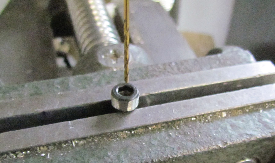
Drill a .040-inch hole in the cap screw.
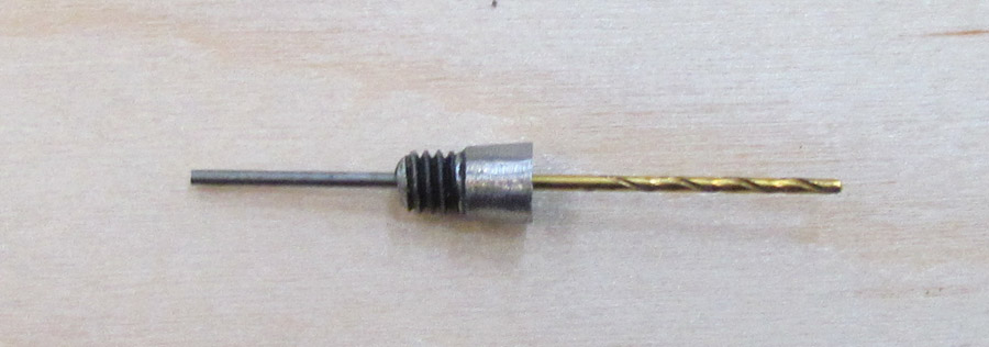
The cap screw after cutting and drilling.
New .040-inch orifice ready for insertion.

Orifice screw with Teflon tape.
Insert the new .040-inch orifice into the gauge base.


I think the orifice diagram you show is incorrect. The FFA AC 43.13-1B says “For an engine cylinder having less than a 5.00-inch bore; 0.040-inch orifice diameter; .250 inch long; and a 60-degree approach angle.”
The 0.040″ diameter portion should be 0.250″ long, and the 60 degree approach angles should not be included in this length. If the 60 degree approach angle was included in the 0.250″ measurement they would have to specify a depth for this angle for all orifices to function similarly.