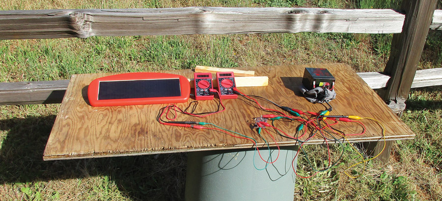
The test setup at 8 a.m. on the 7th of June. At this time, it looked like it was going to be a very pretty day. Note that the author spared no expense for test facilities. An old trash can and a piece-of-junk plywood sheet work just fine as a test bench.
Ah, the signature song of The Weavers. When shall we see a folk group like that again? Probably not in our lifetime.
In 1921, a young feller got the Nobel Prize for showing how sunlight makes electricity. Feller’s name was Einstein, and the technical name for his discovery was the photoelectric effect. It has taken us nearly a hundred years to put this discovery into wide practice. Today that wide practice takes us to an invention in 1903 called the airplane. And the battery. And the starter motor. And how not flying our machines every day leads to the battery not batting, and consequentially, the starter motor not starting.

The gel-cell battery getting the charge.
The problem is that keeping a trickle charger (even most of the smart ones) on our batteries leads to bad juju inside the battery, especially those with the AGM (glass mat) method of construction. These little rascals like to go up to full charge, then periodically drop back down to a lower level, then back up and so forth. Sort of like our bodies don’t like to work at full speed 100% of the time. We need to rest and (you should pardon the expression) recharge our batteries and then go back to work.
It is also true that even if you get a trickle charger that does the cycle-on, cycle-off routine, you need commercial AC power in the hangar or at the tiedown to plug into. We do have a free power source that is available every day that we don’t need to plug in—the sun. The nice part about using the sun and a solar charger on our batteries is that we have an automatic charge timer on them. It is called the sun going down at night and coming back up in the morning. Charge during the day and ever so slowly discharge at night…and then back up the next day and so on. Serendipity strikes again.
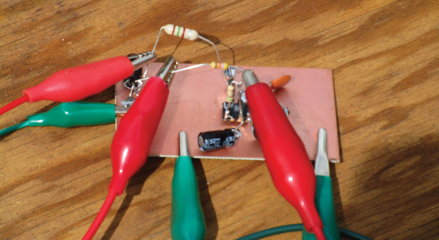
The little charge regulator circuit. Note that for breadboard circuits, we use “dead-bug” construction where the parts are put on the board upside down with their leads in the air. This gives the effect of a dead cockroach.
The prime mover in this little scheme is an inexpensive solar charger from the aviation department of our favorite airplane parts store: Harbor Freight. The HF 62449/68692 solar charger is rated at 12.5 volts at 1.5 watts…which is a rather strange way to rate a charger. Usually it is volts and amps, not volts and watts. The kicker is that the little beast puts out about 22 volts in full sunlight and expects the battery to drag it down so that it doesn’t overcharge. That problem goes away if you only charge a day or two and then drive the car. With the airplane in the hangar for a week or two, and with the small batteries in our aircraft, I see the probability of overcharge and ruining a perfectly good (and perfectly expensive) battery.
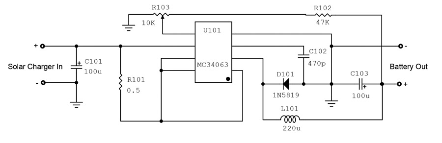
Solar battery charger regulator.
There are going to be a couple of relatively simple problems to solve to make this $12 charger do the job for us. First of all, we are going to use a power charge converter to take the output of the solar charger, which is too high volts and too low amps, to the correct voltage with an increase in amps. Let’s say that again. Our little charge controller is going to take power (the product of voltage times current), decrease the voltage, and increase the current at about a 90% efficiency. We will throw away a few milliwatts in the process as heat, but we get a pretty decent boost in charge current for our trouble.
The schematic shows the relative simplicity of the charge controller. One IC, three resistors, three capacitors, and one inductor are all we need to make the controller, including a nighttime charge leak to drain the battery down just a little.
The question then becomes, how do we get maximum power out of the solar charger? The answer is easy to say, somewhat difficult to implement. The easy answer is just keep the charger pointed at the sun at all times. The difficult part comes when you have to climb up on the hangar roof every day and every hour to repoint the charger. Not a good idea.
Some pretty smart folks have done some calculations that show the best constant angles to point the charger for maximum insolation or capture of the sun’s energy. All calculations are done with the charger face pointing due true south. Here are the calculations (“latitude” or “lat” is the latitude of your homedrome).
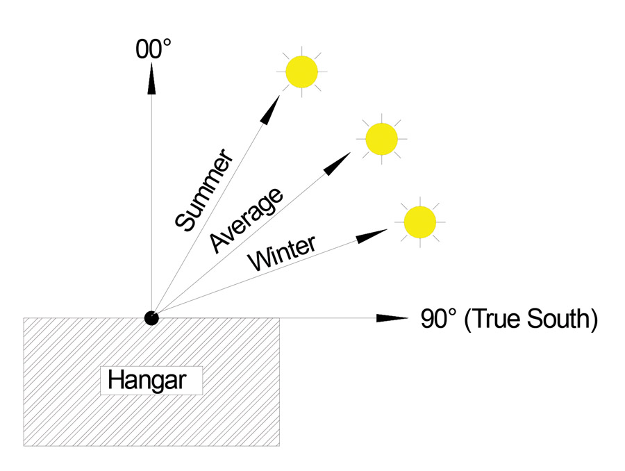
Solar charger aiming angle.
If you don’t want to repoint the charger at all and are willing to take less charge in both winter and summer than is possible, just do the following calculation:
Angle = (lat * 0.76) +3.
For example, the home airport latitude at KGOO (Nevada County Airport, California) is 39, so the compromise angle is 33. The efficiency at this point is 72% of what you could achieve with perfect charger tracking of the sun.
If you don’t mind repointing for summer (on the 30th of March) do the following:
Angle = (lat * 0.93) – 21
And in winter (on the 29th of September) do the following:
Angle = (lat * 0.87) +19
Your overall efficiency increases to 76%. Again, at KGOO, these angles are 15 and 53 for summer and winter respectively.
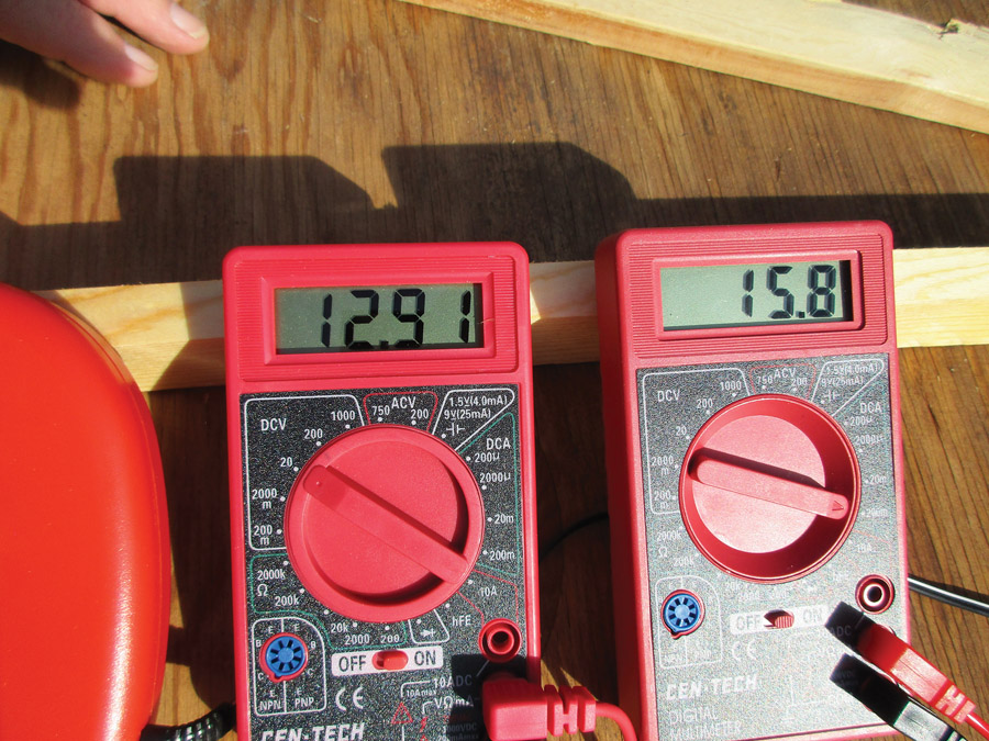
The test was started at 9 a.m. Still looks like a nice day, and our 12.91-volt battery is getting 15.8 mA of current charge
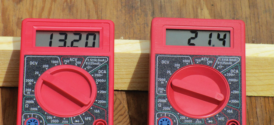
By 10 a.m. the clouds had started to roll in, but we were still generating 21 mA of charge.
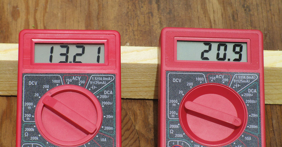
It’s now 11 a.m. Note that even with this small amount of current, the battery is now up to 13.21 volts, but heavy cloud cover dropped the current to 20 mA.

By 2 p.m. the clouds had slightly parted and we were getting 24 mA into a 13.22-volt battery. Other tests I’ve done with this same device and charger are easily double this current in bright sunlight.
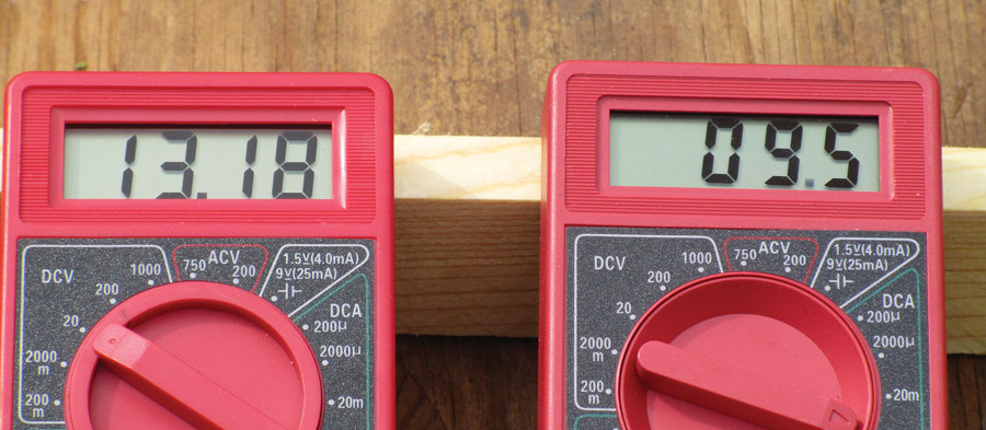
At 5 p.m. the sun was nearly down, we were down to 9 mA, and the battery had started to go down in voltage for the night.
Here are a few questions that I think this project might pose:
Q. Harbor Freight has some 5 watt and 13 watt chargers. Will this controller work with them?
A. The 5-watt charger is a 5-volt charger for cell phones and tablets. No, it won’t work. The 13-watt charger is a 12/24-volt charger. This controller will probably work in 12-volt mode. I don’t know if it is weatherproof to the point where you can leave it out in the elements.
Q. Will low temperatures affect the rate of charge?
A. Yes. The colder the temperature, the better a solar charger works. While the sun is much lower in the sky and is visible for fewer hours in a day, the colder temperatures will help increase the current output.
Q. The case of the charger is plastic. Will it deteriorate over time?
A. Yes. I’ve painted one with silver “UV” dope, and it seemed to increase the life quite a bit. I’m still looking for something that will protect the plastic lens over the solar cells and haven’t found anything that doesn’t drastically decrease the charger’s output.
Q. I see that HF has a $70 12-volt 35-amp-hour sealed glass mat battery for sale. Any comments?
A. Yup, lucky you. Experimentals can use any battery the owner wants. My 182 isn’t so fortunate. Caution—the case (+) and (-) terminals seem to be reversed from the aircraft convention.
Hey, that was kind of fun for me. I think we ought to branch out and revisit some of the stuff I did 20 years ago and see if we might want to update it with currently available parts. I haven’t forgotten about the ADS-B article(s) in plain English, nor about the shielded switching power supply for the LED nav lights. All in good time. Until then…stay tuned…
Note: The images for this story were taken on a cold, dark day. You should expect at least double the performance on a typical bright spring/summer/fall day.

![]()
Jim Weir is the chief avioniker at RST Engineering. He answers avionics questions in the Internet newsgroup www.pilotsofamerica.com-Maintenance. His technical advisor, Cyndi Weir, got her Masters degree in English and Journalism and keeps Jim on the straight and narrow. Check out their web site at www.rst-engr.com/kitplanes for previous articles and supplements.


Excellent, Jim!
As a novice (though I built some of your kits back in the 70’s), I need help on the parts required.
Electrolytic caps, or ceramic? R103? Is it variable?: Three taps, one mid-point? R101 a half ohm?
Do you have the parts in kit form, or should I depend on Mouser or Digi-Key?
You had another article using an Eco-Worthy panel (so now I have two of them for this purpose), but I can’t find it…
Thanks!