Rare is the occasion when you make a part in the home shop without some sort of layout work. Most layout work consists of basic tasks like marking hole positions or scribing the perimeter of a part. But occasionally the design or fabrication sequence dictates more detailed work. Whether a part is simple or complicated, good layout is the cornerstone of efficiency and precision in the machine shop.
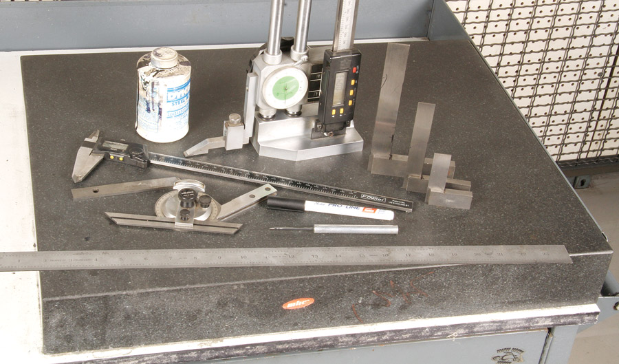
The basics: a ruler, protractor, caliper, a fine-point marking pen, a scriber, height gauge, marking dye, and various machinist squares. A granite surface plate is nice to have, but a table saw or band saw table will work in a pinch.
Layout is a combination of measuring and marking. While dimensions most often come from drawings or sketches, they can be transferred from an existing part (when making a copy) or, sometimes, the best layout is to paste a drawing (1:1 scale) directly to the workpiece.
Most jobs are laid out in two stages. The first is to mark and cut the raw material to a size suitable for making the final part. Sometimes the initial sizing can be close to, or right on, the final size. Other times it makes sense to trim the raw material substantially oversize to make it easier to clamp or put in a fixture for machining. It all depends. If your machining stock is standard bar, plate, or a prepared blank that is already flat and parallel, you often can skip the stock prep and go straight to final layout.
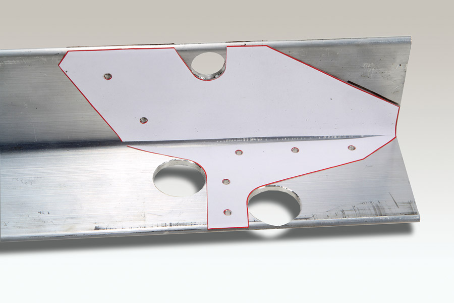
Often the best way to lay out a complex part is to glue a paper pattern directly to the material. This is an L-bracket for a Xenos motor glider. The pattern was spray-mounted to the aluminum angle. The hole-centers were punched and drilled. Sawing and disk sanding will finish the job.
Layout tools can be almost anything: I often use aerosol spray cans as circle templates. You can use whatever works, but there are a few must have items that should be in every machinist’s toolbox: a set of calipers, a scribe (which can be anything pointy), a steel precision ruler, a machinist square (which is different from a carpenter’s square), a protractor, and Dykem Blue. (Dykem Blue is a brand of blue layout ink that you brush or wipe on before scribing. It makes even the lightest scratch mark easy to see.)
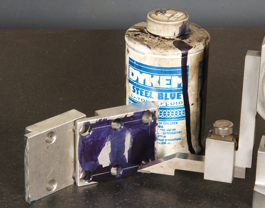
Dykem Blue layout fluid makes the most faint scribe lines visible.
Scribed lines are generally preferred over pen or pencil lines for precision and permanence. Scribed lines can’t get smudged or get washed away. But there are times when you should not use a scriber. Last month I mentioned using an ink pen or a paint marker on aluminum instead of a pencil. While scribing won’t contaminate material like graphite does aluminum, it does have the potential to weaken a part, particularly on sheet metal and especially on sheet metal parts with bends.
On structural parts, keep the scribe lines within the areas of material to be removed.
On thick parts, scribe line lines can usually be machined, sanded, or polished off. If the marks can’t be removed, a good strategy is to scribe short intersecting lines at hole locations and exterior perimeters. That way, the lines are automatically removed by machining, drilling or final sizing operations.
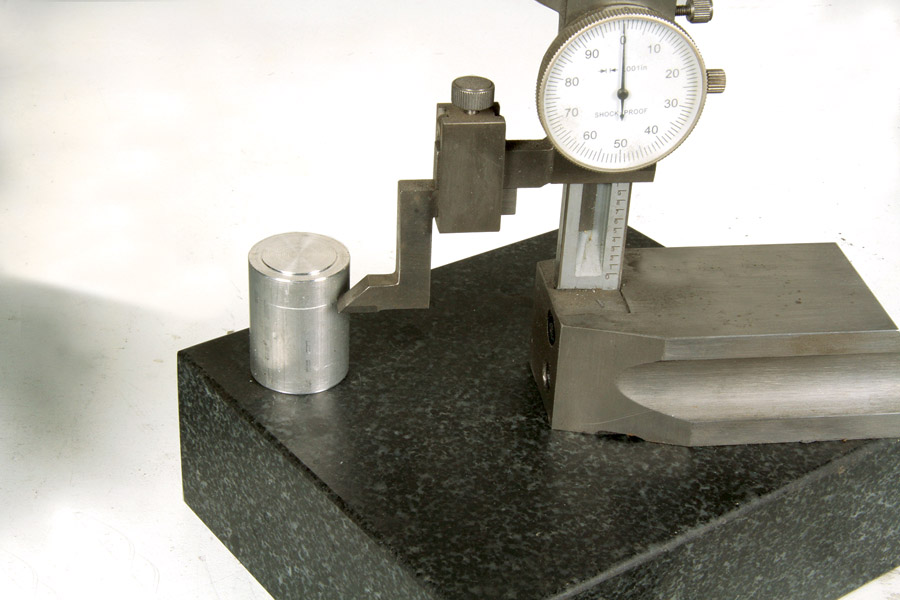
Small surface plates are inexpensive and provide a dead accurate reference plane for scribing precision dimensions.
Although not an absolute necessity, a height gauge and surface plate come in handy for scribing perfectly straight lines from the “zero” base plane of a part. A “B” grade 12×12-inch surface plate is $45 (or less) and a worthwhile investment if you have the space. If a surface plate is not a practical option, any reasonably flat, preferably machined, surface will do, such as a table saw table or band saw table. Height gauges start at around $40 for an inexpensive dial type and go up incrementally for digital and high-precision models.
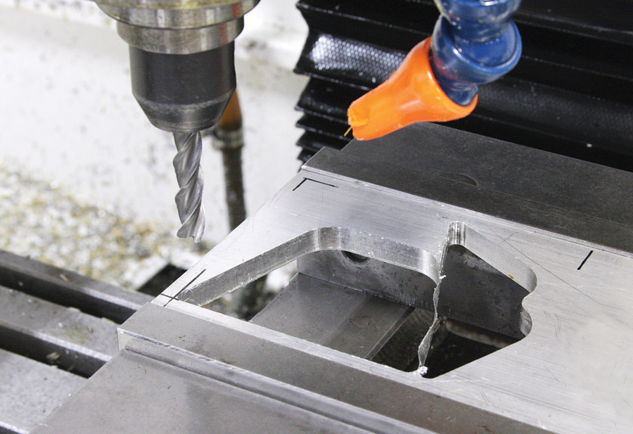
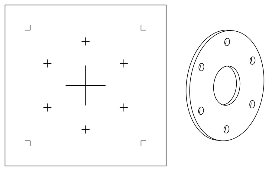
The black lines represent the boundary of the “live area” for this one-off CNC job. The tool path, plus the cutter diameter, determine the margin to the vise jaws.
Parts made on CNC machines generally don’t need layout work, but when making one-offs, I often mark the boundaries of the “live” area to remind me where to set zero so I don’t accidently run the cutter into the mill vise.
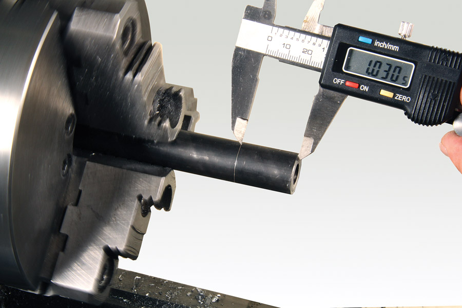
Scribing lathe parts is a simple matter of setting the caliper, running the lathe at low rpm, and lightly scratching a mark just proud of your target dimension. In this example, a 1-inch spacer is marked 1.030 inch in order to have some extra material to face off to the correct dimension.
How much detail you include in a particular layout depends on the complexity of the part and, again, the machining process. Lathe parts rarely need to be marked, but sometimes it’s expeditious to use a caliper to lightly scribe a line to the cutoff point in order to speed up the process.
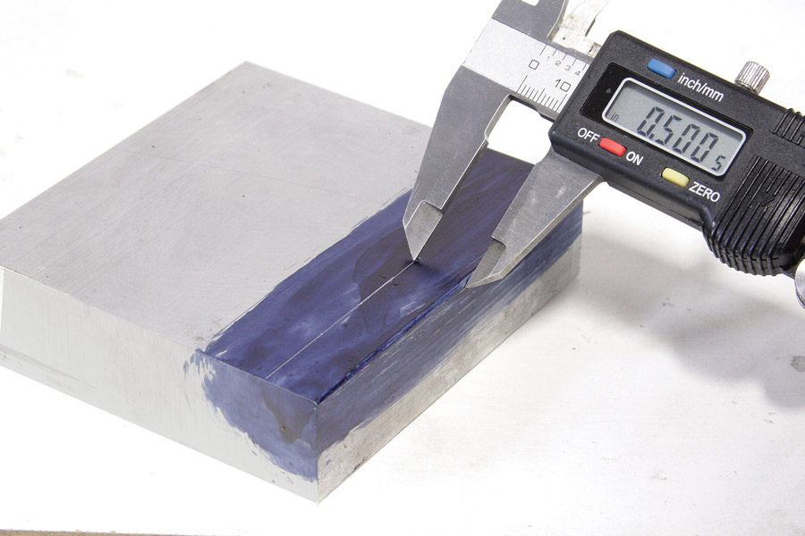
Calipers make quick work of scribing lines close to an edge
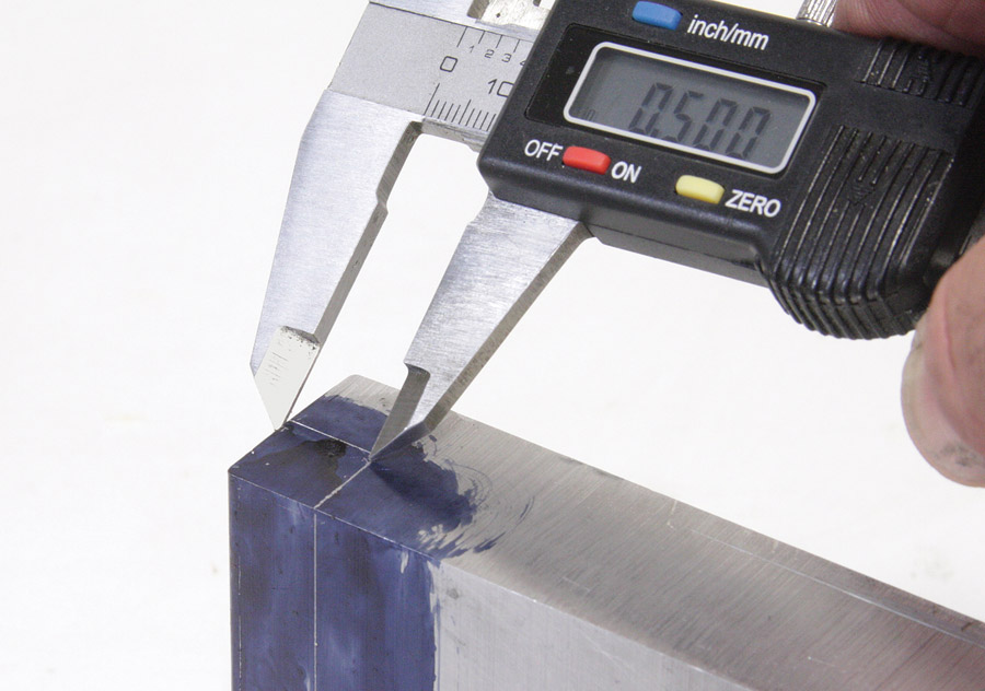
Calipers have hardened jaws, which makes them ideal to make scribe marks. There’s almost nothing faster than a caliper for scribing parallel lines close to an edge. However, the farther you get from an edge, holding it parallel is progressively more difficult. In these cases it’s best to use the caliper to make a small tick mark and then use a straight edge or a machinist square to scribe the straight line.

Scribers and pens should be angled into the straight edge.
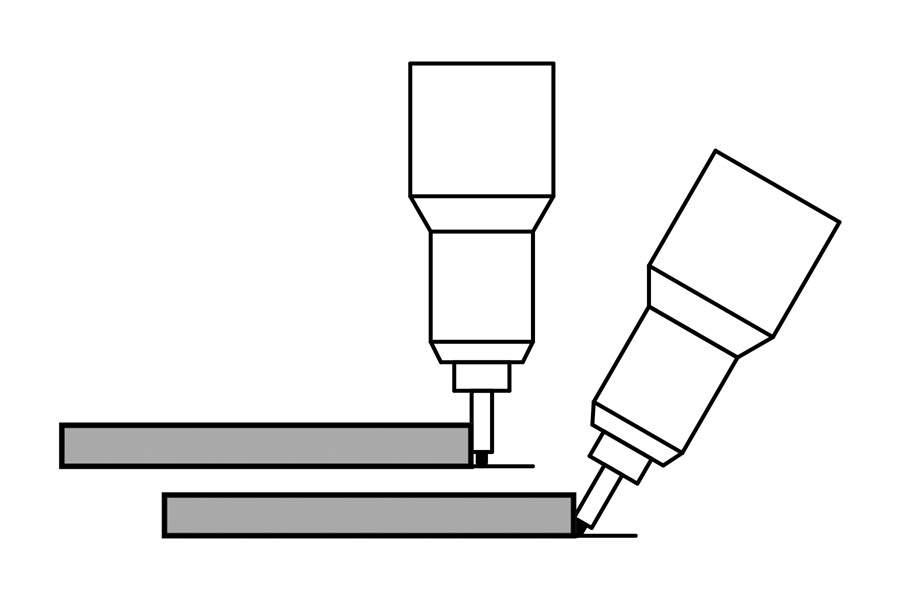
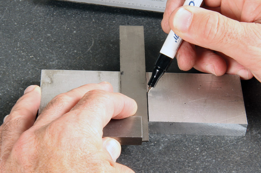
The correct technique for using a machinist square and marking pen.
Some machinists might consider using a caliper as a scribe an abuse of a precision tool. But considering the low cost of imported calipers (less than $15 for a 6-inch digital version at Harbor Freight), you can afford a couple of them for scribing and save your expensive caliper.


