Our Wheeler Express made its first flight September 10, 1998, powered by a 200-hp angle-valve Lycoming IO-360-C1C6. The economics of the time had dictated going with a used engine, with some 500+ hours on its first rebuild. Treated to a set of Lycoming factory-new cylinders, she ran strong and reliably for almost 17 years and some 1200 hours.
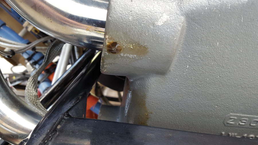
OK, like many aircraft engines, there was the usual sweating of oil in various places, but one day, there were drips running down the nosegear faring after a flight, prompting an immediate cowl removal and look-see. Finding no obvious leak, it was time to wash firewall forward down with mineral spirits, dry it up, and spray with developer—a white powder coating that will show even the smallest traces of oil. I expected to fly once around the pattern to flush the culprit out, but it took no more than a short ground run to deliver the devastating news: a large case crack right under the number 2 cylinder! Some discussion with several mechanics revealed that this was not unusual—a bittersweet comfort.

Crack under cylinder #2—not the kind of thing you like to see.
Decision Time
Now what? A replacement case would run $4000 to $6000, and by now there were some 1600 hours on the bottom end of an engine that had already been rebuilt once. My local helpful mechanic was happy to oversee my rebuild, but then came the deciding factor: One day my always-safety-conscious wife said to me, “Why don’t you just buy a new engine?” Now, there’s an enviable situation—being encouraged by one’s spouse to spend large amounts of money on your winged toy! And so, the path forward started to materialize.
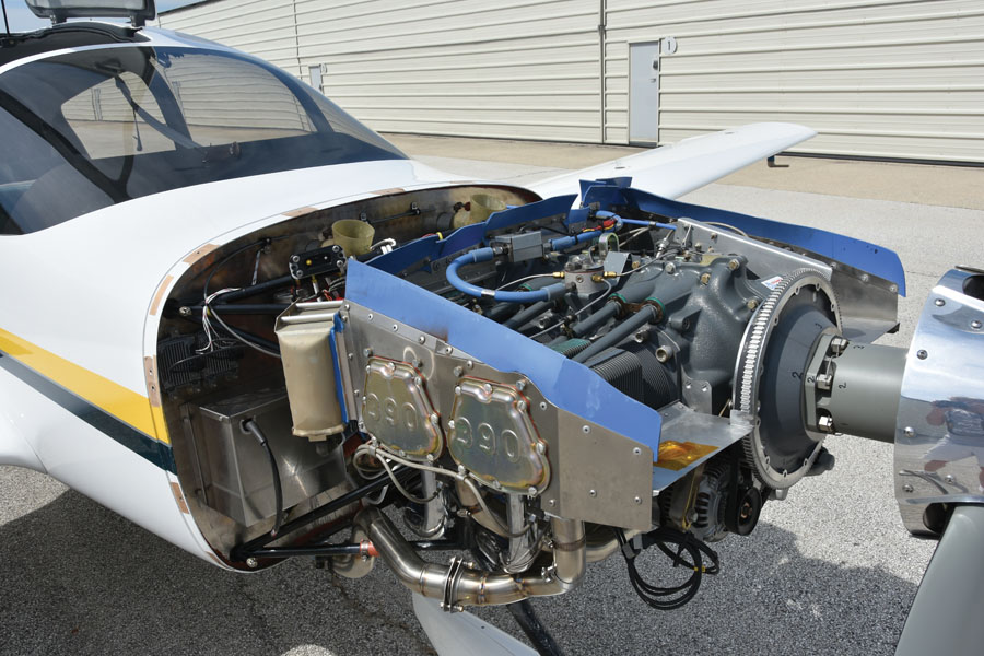
On to the next decision: to just go with a new IO-360 or make some kind of upgrade? Finally, the choice I made was to have an Experimental version of the IO-390 built by the folks at G&N Aircraft, Inc. in Griffith, Indiana. Ten more horsepower, roller tappets, a new more rugged case design, precision reciprocating mass balance, and mounting dimensions essentially the same as the IO-360, so a minimum of installation changes. One significant configuration difference is that the IO-390 is generally configured for front induction while the IO-360-C1C6 is rear induction. Changing to front induction would not only require modifications to the lower cowl, but would also reduce space for the heat muff, which is on one of the front exhaust crossovers. I decided to keep the rear induction and had G&N reuse the air box and intake tubes from the old engine. Time to put in the order and begin planning the surgery!
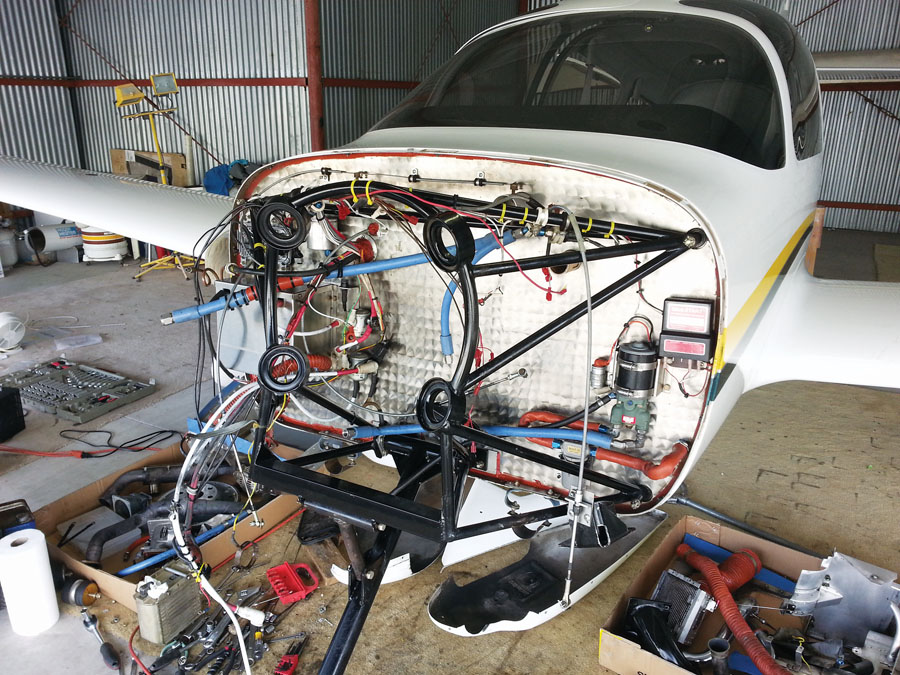
Engine off—a lot of loose ends.
Disassembly and Things to Remember
Probably the most useful pre-disassembly task is to take a bunch of pictures of the existing installation, just in case you forget exactly where that heat muff hose and those sensor wires were routed. It’s also useful to make notes of any particulars that you encounter during the removal that you may want to remember for the new installation.
You’ll need an engine hoist, which nowadays fortunately are not very expensive. First thing then is to take off the prop—it has to come off anyway, and you might as well not have it in the way for all the accessory, hose, and wire removals. As you take off that maze of hoses and wires, take note of any particulars that you may want to remember for the new installation, such as routing and clearances.
For example, when you finally remove the engine, keep track of the sequence and number of engine mount washers used, which were the upper and lower bolts (likely slightly different lengths), and the facing direction of the engine mounts. (To honor the new engine, I bought new ones.) While there is a recommended facing direction for the upper and lower mounts to place the intended half in compression, if you try to figure it out later by looking at some certified planes at your local shop, you’ll be surprised to find some engine installations use them both ways, despite the Lord data sheets—and you don’t want to find out when you finally put on the cowling that the engine is positioned wrong!
Finally, whatever your intended plan is for the old engine, keep it around until you are finished with the new installation. There are numerous things you may want to look at again or even reuse: What was the angle that oil cooler hose fitting needs to point? Which index position should the mags be at to align with the cooling blast tubes? Gee, the new engine didn’t come with that fitting! Etc.
Installation
Engine mount installation is a challenge. Dynafocal mounts are difficult to align and get the bolts through when they are new and uncompressed. Here are two techniques to simplify the job:
1. Install the top mounts first—they are easier to get to and then lowering the engine helps put the lower mounts under compression and closer to alignment.
2. Make yourself an alignment pin by grinding a bolt to a bullet end. When pushed through a mount, it helps pull the pieces into alignment. Pull it back out and follow with the actual bolt. While tightening the bolts, to hold the nuts in the tight space Lycoming provides, it is highly useful to grind the box wrench to fit, particularly for the left lower nut.
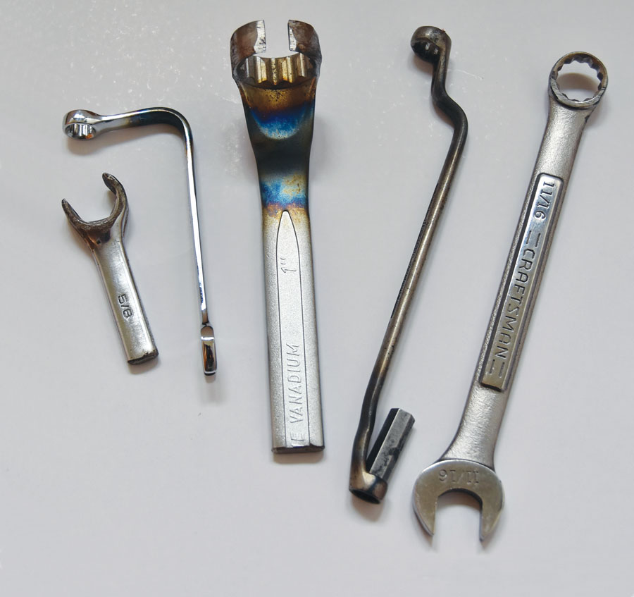
Have torch and grinder, will modify wrenches to fit.
On that topic, one useful thing I have learned is to be willing to sacrifice tools to modification by torch heating and bending and/or cutting to fit the need of a particular job—for example, the pictured offset wrench for the accessory mounted component nuts. The idea of “mutilating” a perfectly good tool hadn’t occurred to me until I saw the collection in my local mechanic’s toolbox.
You may also note in the pictures that I safety wired the intake tubes, not a standard Lycoming procedure. That’s due to an experience one day with a tube coming loose in flight, signaled by a climbing EGT accompanied by roughness. Luckily, it happened really close to an airport.
Surprises
Compared to the IO-360-C1C6, the prop governor moved from the back of the engine to the front on the IO-390. That’s convenient as it gets rid of the front-to-back oil line of AD fame. Since my old Hartzell governor was leaking a bit of oil and was clearly a candidate for rebuilding, I opted instead to buy a new and much smaller PCU 5000. That led to one of my first installation surprises: The stock studs that came with the new engine at the governor mounting pad were too short! Turns out there are a number of different lengths available, and Lycoming had decided to go with those that work for the Hartzell governor—you’d think they would ask first? Taking the short ones out was a real challenge; the usual tightened-double-nut approach to hold onto the stud had absolutely no chance! They were in there so tight that it took all the bite one could muster with a pair of Vise-Grips to get enough of a hold. Talk about a scary undertaking on a brand new engine—the thought of one of those studs breaking off in the case gave me the heebie-jeebies! But a new set of Lycoming correct length studs and a bit of Loctite later, and all was well.
The next surprise was the flywheel. Most of us are familiar with the two Lycoming ring gear tooth counts (149 or 122), and you will likely have been asked what you want or told in the engine ordering process. But did you know there are several alternator drive pulley sizes for the backside of that flywheel? Well, there are, and I found out when my alternator belt did not fit! So be prepared to research which diameter you will have and which belt size fits, or order with the size pulley you want. Luckily, the knowledgeable folks at B&C quickly helped me figure this out.
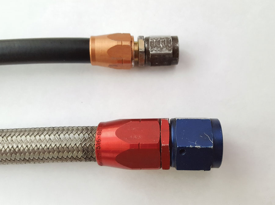
Type 491 and 816 hose/fittings that eventually leaked.
What to Replace, What to Keep
Typically, your new engine will not include a number of accessories, and you will need to decide what to reuse and what to replace. My general philosophy is go new as much as possible, but there are exceptions.
Engine mounts—why start out sagging, even if only a little bit? Replace!
Baffling—now is a good time to repair or replace baffling components as needed. Incidentally, the IO-390 puts out a bit more heat than the IO-360, so if you don’t have the margin to begin with, this may be a good time to plan some airflow improvements.
Exhaust system—inspect and repair/replace as needed. I had some problems with the old exhaust, so a new system from Experimental Aircraft Exhaust in Burnsville, Minnesota, became part of the job. Chris and the folks there did an outstanding job of making exactly what I wanted.
Control cables—some may need to be different lengths and require replacement. In my case, the move of the prop governor to the front necessitated one new cable from the get-go. I also had a recent experience with an ACS throttle cable breaking in flight, so I was motivated to upgrade. I went with new McFarlane cables for all three. They are very well made.
Starter—I went with a new unit, since they do wear out.
Alternator—I added a B&C backup alternator in the process, so the main alternator was safe enough to reuse. Speaking of which, mounted on the accessory pad, the lower left nut is all but impossible to reach. This is one of those cases where a custom made wrench is essential.
Oil cooler—sent out for cleaning and rebuild at Pacific Oil Cooler, it came back looking like new.
Hoses—here’s where I get up on a soapbox: I had already replaced most hoses with custom-made AE466 silicone/Teflon lifetime hoses, which I reused. But I also replaced the remainder of the stainless-steel-sleeved 701 hoses and 491 fittings at this time. These field-assembled hoses are convenient and look nice, but I have found over time the inside rubber hardens at the ends and they begin to leak—not a good thing, especially when it’s a fuel line.
Oil drips should not be here on a new engine.
Pre-Flight Preparations
Just before the engine developed the case crack, I had dutifully sent the propeller out for inspection and rebuild, given its years of service. That turned into an expensive proposition as well, as I received a call from the prop shop that it was out of spec and could not be rebuilt! Apparently when I first bought it used, the shop had taken some liberties with the Hartzell limits since it was going on an Experimental. So, I was cornered into buying a new prop.
With a new prop and governor, it became necessary to set up the rpm limits anew. This is relatively easy, but important so that the brand-new engine doesn’t begin life with an overspeed.
After the specified low-power ground runs to check for oil leaks, the rpm limit can be set. Basically, the prop low-pitch stop sets the static rpm limit, and the governor sets the dynamic—aircraft is moving—rpm limit. So, to begin with, set the prop governor so that it likely will not limit the standing rpm, and run the engine up, but no further than the desired limit, say a typical 2650 to 2700 rpm. If the rpm limit is reached before full throttle, then the pitch stop needs to be set to a greater angle, following the prop manufacturer’s directions, and repeat the runup until the static limit is achieved at full throttle.
No-seepage silicone dipstick tube seal.
If the limit is not reached at full throttle, the prop pitch limit needs to be set flatter. This is easier because you already know the rpm shortfall, and the prop manufacturer typically supplies a number for how much rpm change a particular adjustment will provide.
Next, it’s time to do high-speed taxi tests with the governor set approximately correctly according to the manufacturer’s directions. Once the plane starts rolling down the runway, the prop unloads from the static limit and begins being limited by the governor. At this point it is important to keep an eye on rpm and noting what happens. Use the throttle to back off of full power if any tendency to overspeed is observed. After the taxi, adjust the governor to achieve the desired rpm limit on takeoff roll, and confirm that no overspeed occurs in flight with max rpm and full power.
These runs should be performed expediently to minimize the amount of low-power operation in the beginning of the break-in process. Alternatively, the prop speed limits may be set later, but that requires careful attention to limit power settings on takeoff and in flight to avoid engine overspeeds.

Safety-wired intake tubes.
Break-In
Here’s where I will defer to the well-established Lycoming (or in my case, the additional G&N) instructions. Read and follow them carefully, as it is vital to the life expectancy of your new powerplant. One thing that is not so well known about the IO-390: The typical approach to break-in is to run the engine hard in first flight(s) (and with some power setting variations) to press the rings out and help them seat. That’s usually accompanied by noticeably higher CHTs, which, in my experience, then drop suddenly as the rings seat, say after the first hour or two (or even less). The IO-390 doesn’t behave this way. According to Lycoming, and true to my experience, the IO-390 rings may take as long as 50 hours or more to seat and for the oil consumption to drop. Apparently they are made of a harder material, which is responsible for the longer break-in, and supposedly have a longer service life. Hmm, we’ll see!
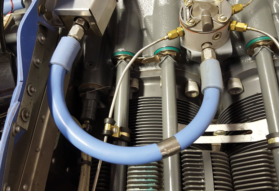
AE466 silicone/Teflon hose with unlimited life expectancy.
Follow-Up
With a new engine, it is a good idea to perform an engine/prop dynamic balance. With the new prop, it was even more important in my case. Dynamic balance, as noted in several previous KITPLANES articles, is vital to the life of numerous aircraft components: exhaust system, instruments, avionics, etc.
So, once the engine seemed reasonably happy, we headed over to my friend and fellow Express builder/owner, Jim Butler, to do the balance, as we had done on several prior occasions. After mounting the sensors and reflective tape on the prop, the usual drill is for me to sit in the plane and run up the engine, while Jim stands to the side with the balance computer and waves when the data has stabilized. We shut down and iteratively place weight on the flywheel until an acceptable level of vibration is reached.
This time, on the very first run, Jim had an incredulous look on his face as he waved to stop the first run. Engine shut down, he held up the computer screen and said, “We’re done—0.02 inches/second.” We repeated the run a couple of times just to be sure, but it was true—perfection right out of the box, and a flywheel with no weights on it. Lovely! Apparently Lycoming, G&N, and Hartzell had all done an amazing job of balancing all of the components.
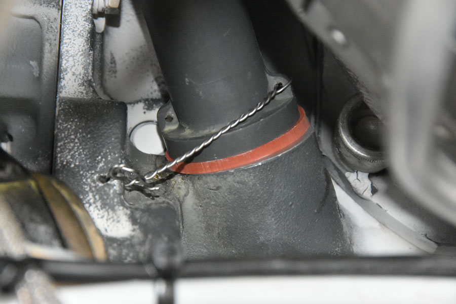
Squawks
As with any big project, there are some things to clear up before all is perfect. I certainly had a few. The first problem was a number of small oil leaks. One was the gasket at the base of the oil filler/dipstick tube, typical for a Lycoming. I found a very nice silicone gasket, available from Aircraft Spruce and Real Gaskets, to replace the standard issue to fix that. Also, while they may start out tight, it is soon necessary to re-tighten the hose clamps on the oil return lines, a typical Lycoming oil leakage/seepage point.
But there continued to be a small amount of oil leakage—not what one would expect from a new engine—resulting in little drips clinging to the bottom of the airbox. After a cleaning and drying, it turned out to be coming from the mechanical fuel pump—new, Lycoming supplied—leaking both from its own seals and at the engine-mount gasket. I decided to replace the pump with one from a different manufacturer, installed it with silicone gasket sealant, and the leaks were finally all gone.
The real big surprise was that the fuel pump replacement unexpectedly fixed two other squawks: Coincident with the new engine, fuel flow numbers were about 10% too high, for no apparent reason, along with periodic substantial drops in indicated fuel pressure. Once the new fuel pump was installed, both problems disappeared! Apparently, somehow the original pump was able to make the FloScan fuel-flow sensor generate more pulses for a given flow than it should—perhaps due to pressure pulses, which could also account for the erratic pressure indications.
And the Winner Is…
We’re up to 66 hours now, and the rings are finally broken in. Runs great, though surprisingly had to learn a different starting procedure—the new fuel servo is more likely to flood the engine than the old one. Basically, the procedure is now exactly what the Lycoming manual recommends. Performance with 10 extra hp? I can’t say the top speed is any more, but takeoff torque and climb are noticeably stronger. The belly is staying much cleaner, and the increased sense of confidence and security flying behind a new herd of horses is extremely satisfying!


