Somebody at Oshkosh ’16 is the proud owner of a newish handheld radio antenna…mine. In the hurly-burly of ending my forum on time and loading up to make room for the next guy, I inadvertently left it right where I put it on the speaker’s podium.
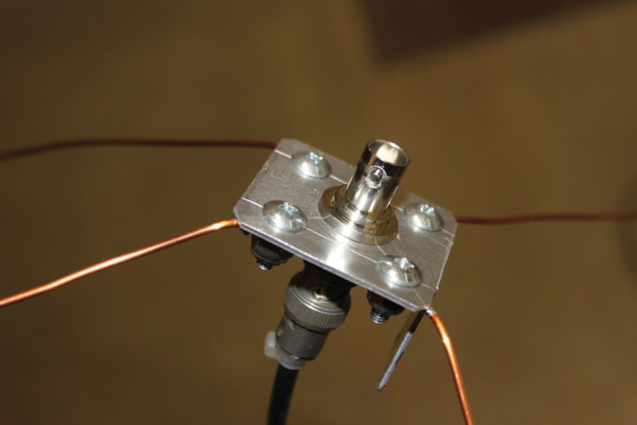
The antenna base with the four radials, BNC cable connection, and the BNC antenna port.
Did I rush right out and buy a replacement? Certainly you jest. Antennas are my bag, and if I can’t gin up a simple “rubber-duckie” antenna then I shouldn’t claim the title of antenna engineer. But how to shrink the venerable quarter-wave antenna to fit neatly on my belt? That took a little doing and “heuristic experimentation”…what some might call diddling around.
Be forewarned, however, that no matter how much trial and error goes into a shortened antenna, it will never approach the performance of a full-sized quarter-wave whip over a ground plane. Never. The only question you can reasonably ask is how bad is it compared to the full whip? Perhaps a better question is how does it compare with the duckie (sometimes called a rubber resistor or a rubber dummy load) that comes with the radio?
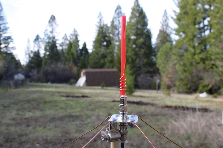
The antenna wound on the McDuckie soda straw.
Fortunately, I had the twin brother of the one I lost that I use in my automobile mobile radio setup, so I can compare my little gem with one that comes store-boughten from the radio shop. I can say with some confidence that it is every bit as good (or bad, if you wish) as the factory antenna.
Several problems rear their ugly heads. First and foremost among them is the actual design of the antenna itself. Since I wanted to make it as much like the original as possible, this created the constraint that the antenna part itself (not including connector) needed to be no more than 6 inches long. That meant that I had to put a resonant 23-inch antenna into something about a quarter of that size. The only way I know of doing that is by using what we call “base loading,” which in simple terms means putting an inductor at the base of the antenna. How much inductance and how do we fasten it to the center pin of the connector on one end and the short wire antenna on the other end? Now we leave the realm of theory and start cutting and pasting to see what works.
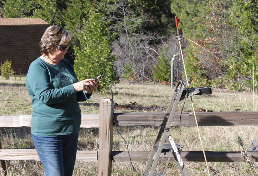
The technical advisor working the test radio for the little red soda straw antenna. Note the “sophisticated” RST Engineering antenna pattern range.
The best antenna-tuning tool I’ve ever used goes by the exotic title of “wire cutter.” The drill was this: Cut a resonant quarter-wave antenna for 123.0 MHz, 24 inches long out of #14 Romex house wire. Strip both the black and white wires completely free of insulation. This will give you three #14 bare copper wires 24 inches long (one from the white, one from the black, and the ground wire). Cut another identical piece. This will give you six 24-inch wires. Use four of them to make a ground plane as shown in the photo. Use a piece of scrap aluminum for the antenna base, drill four #6 clearance holes in the corners, and a half-inch hole in the dead center of the base for a BNC female bulkhead connector.
The antenna connects to one side of the BNC bulkhead connector, and the radio coax lead-in connects to the other side. My preferred method of experiment (since I have absolutely no way of calculating the input impedance of a 5-inch piece of wire at 123 MHz) is to take a resonant quarter-wave 23-inch antenna, make one turn of wire, and see what happened to the resonant point. Cut the antenna shorter to resonate at the desired frequency. Lather, rinse, repeat. It just so happens that five turns of wire resonates with 5 inches of antenna at 123 MHz (sort of, kind of, a goosey resonance) and that is our antenna.
Not quite. I really don’t want a wire poking me in the side when I put the radio on my belt, so we need some sort of flexible rod to fasten the wire for support. I tried a lot of things, and what worked best was a long thin pencil eraser we used to use in the electric erasers before computer aided drafting. I still have a dozen of those old rascals around, but a web search showed that you can still get them, but only by ordering a dozen at a time and at an unbelievable price.
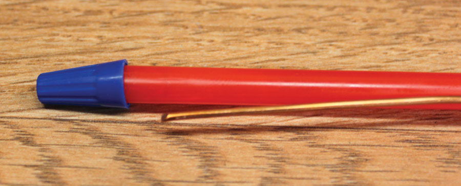
A wire nut is used as the antenna top.
So here I sit in McDonald’s, enjoying a vanilla shake and pondering the problem of what to use for this flexible rod. Right there in front of me sits this…red soda straw full of ice cream. About a quarter of an inch in diameter, plastic, and very flexible—especially full of ice cream. Since I don’t expect the ice cream to survive an Oshkosh summer, I think we ought to fill the soda straw with some other flexible filler…something like silicone caulking. Problem solved.
That defined the diameter of the coil. Take a drill bit and see if it will fit inside the soda straw. When you find the one that is one diameter larger than the one that fit, you have found your coil form winder. For example, a quarter-inch drill bit just barely fit into the straw, but the next larger size (9/32 inch) would not fit. Therefore, the five-turn coil mentioned above was wound on the 9/32-inch bit.
One last touch and we are done: Somehow, we have to put the finishing touch on the top of the antenna. Once again, serendipity rears its lovely head. While working on another house electrical problem, I reached for a wire nut—a plain old wire nut that fits quarter-inch red vanilla shake straws like a glove. Shrink sleeving puts the whole thing together and makes it hermetically sealed against the weather.
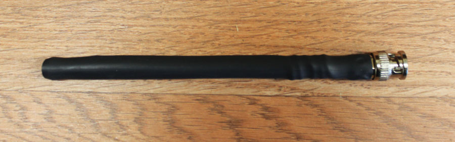
The finished antenna covered with shrink sleeving.
There you have it friends. A rubber-duckie antenna for way less than $5 and works every bit as well (or as poorly, your call) as the $15 store-boughten variety.
So what’s upcoming for the rest of the year. Shucks, you all have been feeding me a lot of stuff that I’m happy to work into an article for the rest of the brethren and sistren (send me more stuff, I love solving problems). How about a little inexpensive circuit that will let you run a 10-LED graph for such things as flap position, fuel quantity, oil pressure…indeed any quantity that can give a voltage out for a quantity in. Or how about a short treatise on the various MIL-SPEC wire types that we can use in aircraft. It is shaping up to be a good year. See you next month. Until then…stay tuned…

![]()
Jim Weir is the chief avioniker at RST Engineering. He answers avionics questions in the Internet newsgroup www.pilotsofamerica.com-Maintenance. His technical advisor, Cyndi Weir, got her Masters degree in English and Journalism and keeps Jim on the straight and narrow. Check out their web site at www.rst-engr.com/kitplanes for previous articles and supplements.


