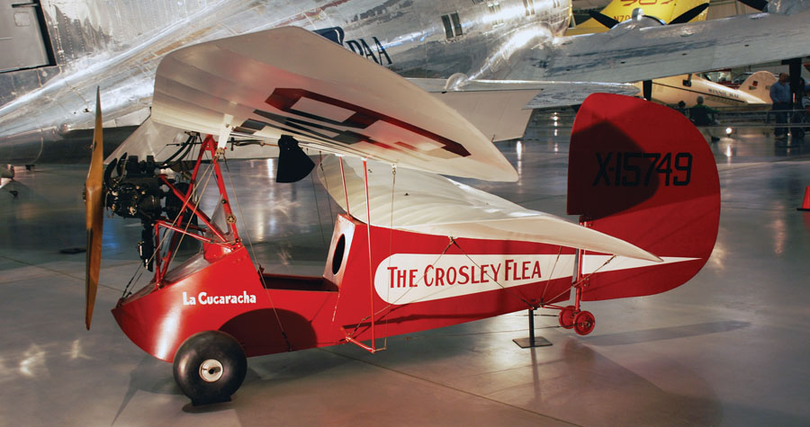
The first HM.14 to be built and flown in the U.S. was completed in November 1935 and is now on display at the Steven F. Udvar-Hazy Center. (Photo: Jarek Tuszyński [CC BY-SA 3.0], via Wikimedia Commons)
For the past two months we have been looking at the story of the Mignet HM.14 Pou-du-Ciel (Flying Flea) and its dangerous behavior. We continue this month with a closer look at the cause and cure of its problems.
The numerous fatal crashes suffered by the original Pou, coupled with the findings in full-scale wind-tunnel tests in Britain and France that it suffered from dangerous instability, led to the type being grounded, and in some countries, banned.
As we saw last month, understanding of the cause of the Pou’s problems was severely flawed. The ban was based on the erroneous idea that the dangerous flying qualities were intrinsic to the whole class of configurations, rather than type-specific flaws with the HM.14 itself.
In spite of all of this, Henri Mignet persisted, and fixes were found that made the basic “flea formula” viable. After the initial tragic problems with the HM.14 were fixed, Mignet continued to build successful Flying Flea type airplanes for the rest of his life. None of these met with much commercial success, but the Mignet formula survives to this day, particularly in Europe. Aircraft using the Pou configuration have varied in size from single-seat microlights to the 180-hp Croses Para-Cargo, which had a span of 31 feet and a maximum gross weight of almost 2500 pounds.
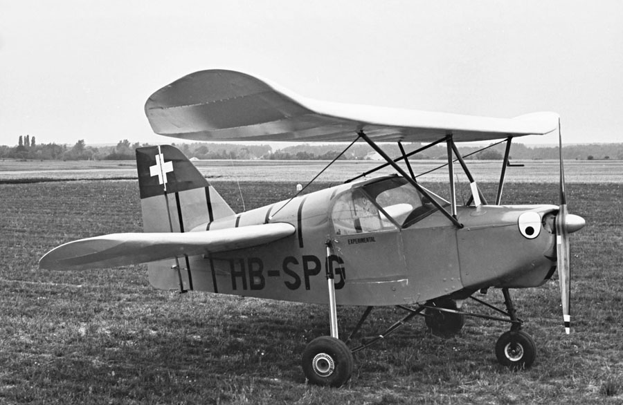
Don’t have a tailwheel endorsement but want a Flying Flea? You can build an HM.14 with tricycle gear. (Photo: Happy Days Photos and Art [CC BY 2.0], via Wikimedia Commons)
Understanding the Problem
Although a lot of speculative nonsense was published at the time of the original Pou accidents, some contemporary engineers had a more realistic understanding of the issues with the HM.14. E. L. Baynes, the designer of the Abbott-Baynes Cantilever Pou, wrote about it in Flight magazine (Oct 22, 1936 pp 406-407 [http://tinyurl.com/jj58jna]). Most importantly, he realized that there was no magic “alternate aerodynamics” happening, commenting:
“Provided the Pou is correctly designed according to the accepted rules of the game (and I am sure that, fundamentally, it is perfectly sound), there is so much to be said in its favour…”
He noted that with CG farther aft than 40% chord of the forward wing, the airplane would be unstable and opined that the far-aft CG positions of most standard Poux were “the primary cause of the accidents to Poux in France.”
In keeping with the idea of using a conventional engineering approach, he stated, “the machine should be regarded as a monoplane with a large tail, rather than as a tandem-wing machine” because with the CG far enough forward to be stable, the rear wing was carrying a relatively small portion of the lift.
Mr. Baynes had it mostly right, and in keeping with his wise counsel to “design according to the accepted rules of the game,” let’s look further at the HM.14.
The Pou Configuration
The Pou configuration has several features that differentiate it from conventional airplanes:
- Tandem-wing configuration with short fuselage.
- High-mounted front wing on struts and low center of gravity (CG).
- Longitudinal control by varying front wing incidence.
- No ailerons: All lateral/directional control provided by the rudder.
Since our primary focus here is on longitudinal stability and control, the last item is not significant. What is most important is how the combination of CG, the variable-incidence wing control, and the presence of the rear wing play together.
Viewed in this light, the Pou looks very much like a modern trike with a large tail (rear wing) added to it. The CG is well below the front wing, and the variable-incidence pitch control works exactly like the control bar of a trike.
It’s easy to fall into the trap of thinking of the fuselage as inertially fixed and see the primary effect of changing wing incidence as a change in wing angle of attack. This is not the case because the fuselage is not fixed. It’s hanging from the wing and free to pitch. Moving the stick changes the angle between the wing and the cabane struts, suspending the rest of the airplane below it. This moves the CG forward or back relative to the wing in the same way moving the control bar of a trike does.
The low CG causes the pitching-moment curve to have the same type of nonlinearity we saw a few months ago in our discussion of trikes. The airplane becomes more stable as angle of attack increases, and less stable as it decreases.
The rear wing, which is fixed to the fuselage, stabilizes the airplane and adds a relatively linear stability increment. Accordingly, a Pou will have an aft CG limit that is farther aft on the front-wing chord than a trike. The trap Mignet fell into was thinking that, as a tandem-wing airplane, the Pou should have a CG very far aft to share load between the front and rear wings.
Analysis
With this in mind, let’s now analyze the Pou the same way we did a few months ago for trikes. The analysis that follows uses linear methods and does not model stall, flow separation, or any mysterious “slot effect.” It does properly model the effects of both the horizontal and vertical positions of the center of gravity relative to the lifting surfaces.
We start out using the geometry of the original HM.14 (G-AEFV), as measured by the Royal Aircraft Establishment for its wind-tunnel test with the CG placed at 50% of the chord of the front wing. Figure 1 shows the pitching moment for this machine at three wing-incidence settings (stick positions).
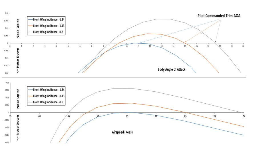
Figure 1: HM.14 with CG at 50% of front wing chord.
Looking first at the top plots, we see characteristics very similar to those measured in the wind tunnel. The airplane is stable at high angles of attack and becomes progressively more unstable as angle of attack decreases. At the stick position that trims the airplane at 11 degrees angle of attack, the airplane is on the edge of a cliff. Any change in angle of attack, either nose-up or nose-down, will result in a negative pitching moment. The pilot cannot command any angle of attack less than this and trim the airplane in a stable flight condition.
There are trim points at lower angles of attack, but at these points the airplane is unstable and the trim stick position is aft of the trim position for 11 degrees. To get there, the pilot would have to push forward enough to drive the angle of attack below 11 degrees and then pull back to arrest the nose-down pitch rate that would be increasing. In this flight condition, the airplane would be quite unstable and require constant corrections to prevent it from diverging in pitch.
Looking at the lower plot, we can see what this means to a pilot trying to fly a specific airspeed. At speeds below 55 knots the airplane trims at a stable point, and the relationship between stick position and trimmed airspeed is stable: stick back trims slower, stick forward trims faster. If the pilot pushes forward a little too much to command an airspeed above 55 knots, the airplane will pitch down at an ever-increasing rate as airspeed increases, unless the stick is pulled back well aft of the trim position for 55 knots. In this regime, the airplane is unstable and will be very difficult to control.
As we discussed in some detail in Part 1 of this series, a pilot, particularly an inexperienced one, is very likely to be caught out by this behavior and be unable to react quickly enough and correctly enough to maintain control of the airplane.
Now, per the recommendation of Mr. Baynes, lets look at moving the CG forward to 40% of the front wing chord. The results of this change are shown in Figure 2.
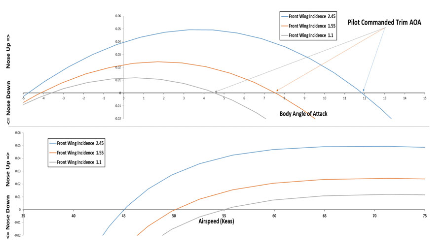
Figure 2: HM.14 with CG at 40% of front wing chord.
The angle of attack at which the airplane becomes unstable is now much lower, and it maintains the ability to command nose-up pitching moment to negative angles of attack. The variation of stick position with trimmed airspeed is now stable (stick back for slow, stick forward for faster) to well above 55 knots. This is a flyable airplane. It would still be uncomfortable to fly much above 55 knots because the stability degrades at higher airspeeds, becoming neutral at slightly above 65 knots, and unstable faster than that. Still, Mr. Baynes had it right. With the CG at or ahead of 40%, the HM.14 would be unlikely to end up in the unrecoverable dive that caused most of the accidents.
The final fix to the basic configuration was likely the result of getting the right answer for the wrong reason. As we saw last month, some people believed that the close proximity of the trailing edge of the front wing to the upper surface of the rear wing when the stick was back caused a Venturi effect that increased the lift of the rear wing and forced the nose down. They therefore concluded that the rear wing should be moved aft far enough so that the two wings did not overlap, and all post HM.14 Fleas have had this feature.
In fact, the wind-tunnel results show that this Venturi effect did not happen, but moving the rear wing aft did have favorable effects for a much more prosaic reason: Moving the rear wing aft acts like increasing the tail arm of a conventional airplane. It increases the stabilizing influence of the tail (or rear wing in this case).
Figure 3 shows our HM.14, with the CG at 40%, and the rear wing moved aft 25% chord from its original position. The plots show that, while some nonlinearity remains, this version of the airplane remains stable over the complete pre-stall angle of attack range. (Stall is not modeled in this analysis).
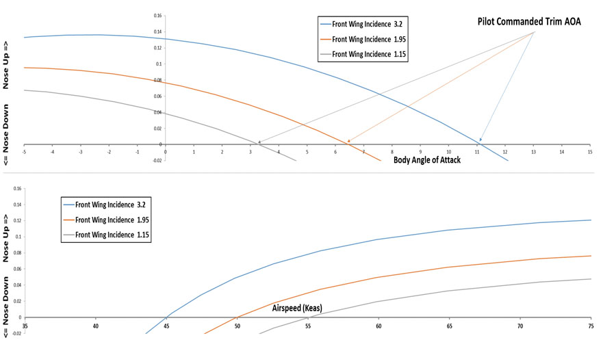
Figure 3: HM.14 with CG at 40% of front wing chord and rear wing moved back 25% chord from original position.
From the above, we can see that Mr. Baynes’ assessment of the Pou was substantially correct. The basic Pou configuration is reasonably sound, provided it is properly designed and analyzed. The divergent dive characteristic of the original HM.14 is predicted by conventional analysis, provided that analysis properly accounts for the effects of the vertical position of the CG and the variable-incidence front wing.
The tricky bit here is that both of these effects are normally ignored because they are small enough to be treated as negligible on conventional configurations.

![]()
Barnaby Wainfan is a principal aerodynamics engineer for Northrop Grumman’s Advanced Design organization. A private pilot with single engine and glider ratings, Barnaby has been involved in the design of unconventional airplanes including canards, joined wings, flying wings and some too strange to fall into any known category.


