The elusive Skyotë is a rare plansbuilt aircraft that some people have heard of but few have actually seen. The design dates back to the 1970s when it was created by Pete Bartoe. His goal was to create a plane that was affordable and easy to fly, with enough performance to be competitive at the International Aerobatic Club’s Intermediate level. Bartoe met his design goals, and the delightful handling qualities of the Skyotë were praised by none other than R.A. “Bob” Hoover in a flight report that appeared over 40 years ago in the December 1976 issue of Sport Aviation.
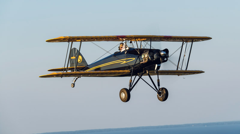
The Skyotë uses a biplane planform, with a swept wing that will remind you of a B cker B 133 Jungmeister. It has a single seat, tube-and-fabric fuselage with an all-aluminum structure, and fabric-covered wings stressed for +9/-6 G. Weight and performance qualify it for the Light Sport category, and it uses a Continental O-200 engine.
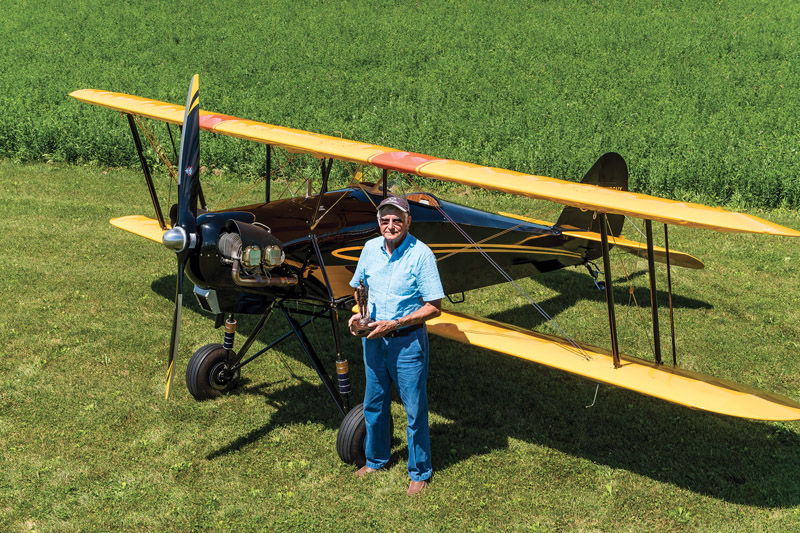
A literal field of dreams: green grass, pretty biplane, a proud builder, and a Bronze Lindy.
So, why have you never seen a Skyotë? Probably because there aren’t many around. The airplane is not a typical plansbuilt homebuilt. In fact, Bartoe did not design it with homebuilding in mind; his intention was factory production.
Because the goal was good aerobatic performance on minimum horsepower, each part is optimized for its purpose. As a result, parts are made from six gauges of aluminum, seven gauges of steel, and three gauges of stainless steel. The 7.2-degree wing sweep looks and performs great, but is hard to build. Brackets in the wings have left, right, top, and bottom positions, so one part can have four different bending configurations depending on what wing location you’re building. The mounting clips for the wing ribs have an acute angle on one side and an obtuse angle on the other side.
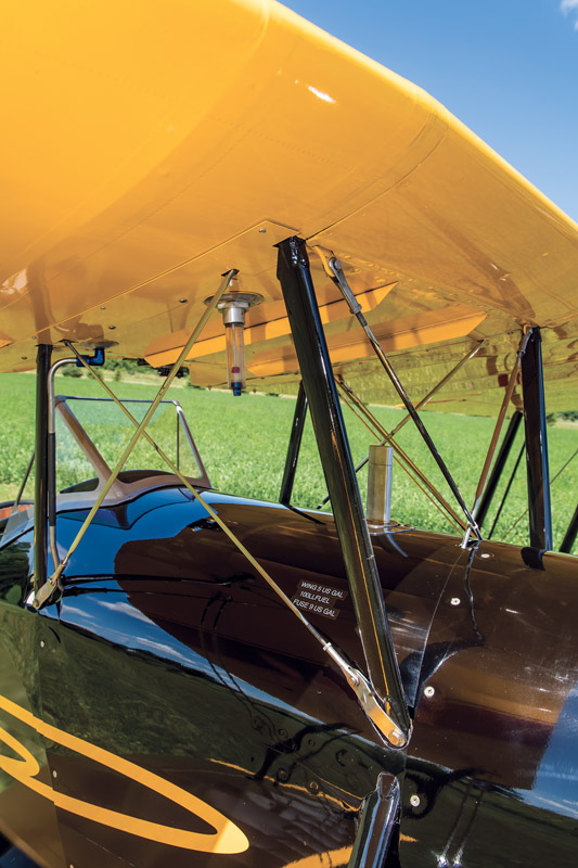
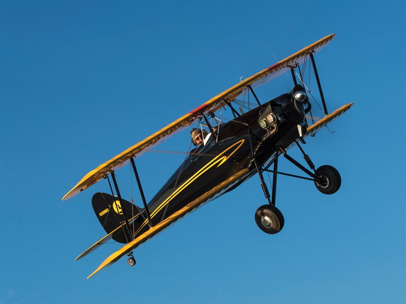
Many Bruntons flying wires are required for the +9 G/-6 G load rating. The wires virtually disappear in flight.
Although the Skyotë didn’t make it to production, Bartoe sold around 100 sets of plans. Twelve airplanes have been completed from the original plans, but about half of those were factory prototypes.
John Roberts was one of those people who ordered a set of plans. But when he received them, it didn’t take long to discover why only five builders had completed their airplanes after nearly 40 years—the drawings were incredibly complicated, and the skill level required was way beyond the ability of most potential builders.
This might have been the end of the Skyotë story, but John had a better idea. He decided to use modern technology to get his plane, Skyotë #88, into the air. He also came up with a name for his project: the Tech-Built Skyotë.
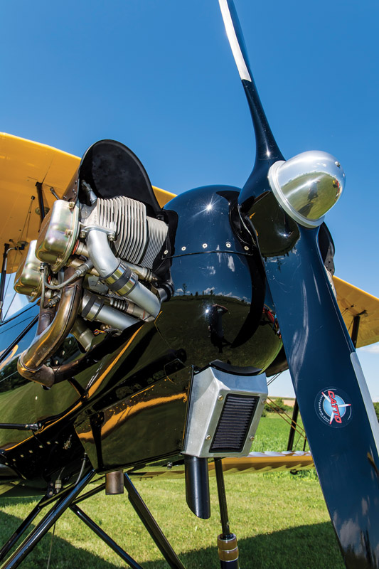
The two-piece cowl with its English-wheel-formed aluminum nose bowl. The engine is a Continental O-200.
Fulfilling a Dream
John is like many readers of KITPLANES—for as long as he can remember, every time an aircraft flew over, he looked up to see what it was. John was born in 1941 near Rock Hill, South Carolina, the oldest of four sons. Much of his childhood was spent devising contraptions to entertain his younger brothers (most of which were not actually meant to maim or injure them as they now claim). John’s father ran a painting business. Because most summers were spent working with his dad, he learned early on the value of hard work.
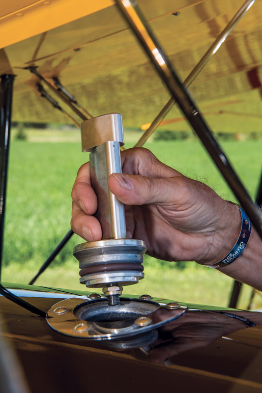
John modified a standard flush cap to add a streamlined main tank vent stack. A long gun-drilled stud and threaded top knob replace the regular toggle latch assembly.
When John was about 4 years old, playing in a wheat field near home, he watched a Piper Cub land nearby. Two nuns in full habits emerged from the plane, which had run out of fuel. (You can’t make this stuff up!) According to John, this was his first up-close glimpse of an airplane. At age 7, while playing in the surf at Myrtle Beach, to his astonishment a V-tail Beechcraft Bonanza flew low along the coast. He was thrilled by the sight and declared to himself that one day he would fly one of those.
John majored in mechanical engineering at Clemson University. After 10 years of working at various engineering jobs, he decided it was time to explore his entrepreneurial roots. In 1977, in his garage with his wife and two young daughters, he started his own design/engineering firm. He was pretty good at it, and the company is still in business today.
While he ran Roberts Systems, John met the goal of flying a couple of Beechcraft Bonanzas—a V-tail and an A-36—while traveling for business. He also owned a WACO YMF-5 biplane for a while, and it is still one of his favorites. For his first venture into Experimental kit building, John and friend Les Kanna built an RV-7A. A few years later, looking for a new project, John came across the Skyotë and was hooked.
Learning Something New
John realized early on that building the Skyotë in the traditional manner was not for him. Knowing that Pete Bartoe had mathematically calculated all Skyotë dimensions to an accuracy of three decimal places for all three axes led John to see the combination of Skyotë plans and 3D CAD as a better way to have the Skyotë he wanted.
Engrossed in management of his own company when CAD came on the scene, he saw the Skyotë as the perfect project to develop his CAD skills. He did some research and selected Geomagic 3D CAD software.
While learning the software, John selected parts from Bartoe’s drawings and created CAD models for each part. Over time, he ended up with more than 150 drawings depicting nearly 600 parts that needed to be fabricated for the Skyotë.
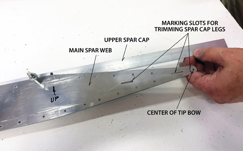
John added a feature to the Tech-Built spar webs that allows the spar caps to be marked for trimming. The spar web comes pre-tapered.
The software’s 3D modeling feature produces assembly drawings that are very easy to understand. By assembling the parts in “virtual space,” you can be sure that all of the parts will fit together correctly.
The CAD program also confirmed the accuracy of Bartoe’s original calculations. With a total of nearly 1000 pieces in the Skyotë and tens of thousands of holes, John discovered only one small error—a single hole was off about 1/32 inch. That discrepancy has been corrected.
Each of the four spar caps is individually deflected to be flush with the tip of the spar web and marked.
The next step was finding a place to convert his .dfx files into parts. As luck would have it, John found Pritchard Technologies, a waterjet shop near Clover, South Carolina, just three miles away from his house. Pritchard does precision part cutting, and anything up to 9-inch-thick stainless steel is possible. The waterjet cutting process is extremely accurate, and about 600 flat metal parts were cut to make fittings for the wings and fuselage.
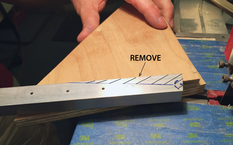
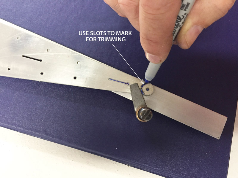
The scribe lines also include the radius of the tip bow tube. This cap is ready for trimming.
It was at this stage of the project that John asked if I would be interested in helping him build an airplane. Naturally, I asked what he had in mind, and when he told me a Skyotë, I replied, “What the heck is a Skyotë,” or words to that effect. I’ve completed a Sonex and enjoy building. But with two children approaching college tuition time, I had little but cheap labor to offer the project. Nevertheless, I welcomed the opportunity to help.

All four caps are trimmed and drilled, forming a perfect nest for the tip bow. The web serves as the template for drilling the caps.
Building the Wings
The entire building process is documented in detail on John’s building log, but here are a few highlights of how we assembled the first Tech-Built Skyotë.
We started by building the wings. There are four, of course, so we had to make sure we built one for each position. We began with the forward and aft spars. All of the holes were match drilled by the waterjet in the caps and web, so we just laid them out and Clecoed them together. At the tip, we used the pre-cut guide slots in the web to assist in final trimming the caps for the tip bow. Next, we pulled down the spar caps, clamped them into place, and drilled for Clecoes. We marked the angle and tip bow mount locations, then did a final trim. We used the same process for the aft spar except there is only one set of spar caps. After referring to the spar detail drawing, we drilled all the holes in forward and aft spar to final size.
At this point all the holes were in the spars, so it was time to add some corrosion proofing. Then we riveted the spars, leaving the holes for the rib clips open. We propped the front and rear spars up on the bench to slide the ribs on. These were hydro-formed by Usher Precision Manufacturing in Oregon. The tip rib has to go on from the outboard side, and all the others from the inboard side. We installed rib clips at each rib location, then added the fittings for mounting the compression struts, N Struts, flying and landing wires. Once everything was on, we properly spaced the ribs off the spars and match drilled the ribs to the clips. There are three compression struts between the front and rear spars, along with drag and anti-drag wires, and one tubular brace out at the tip.
After repeating the process three more times, we were done—four wings were framed up in about four weeks! While it certainly wasn’t as easy as a modern quickbuild kit (or even a pre-punched standard kit), using preformed parts produced from John’s CAD drawings was definitely a whole lot easier than starting from scratch like you would with a typical plansbuilt project.
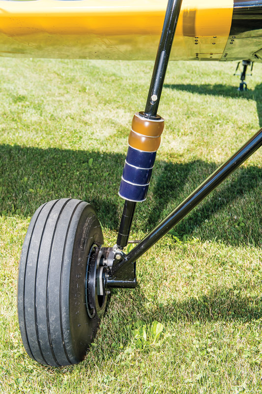
Unlike a bungee, this strut can be tuned for spring rate, preload and ride height.
Fuselage Construction
The fuselage is welded steel tube construction. A conversation with Don VanRaay of VR3 Engineering resulted in the tubing for the Tech-Built Skyotë fuselage, empennage, and landing gear being precision cut on VanRaay’s computer-controlled routers. We began by fabricating a jig to hold all the fuselage tubes. The computer-cut tubes are really amazing—we just looked at a place where a certain tube was supposed to fit, looked at the end of the tube, and slipped it into place. Sometimes I thought there was no way a part was going to fit, but it always did—and perfectly. We quickly discovered that if we had more than a visible gap on any tubing joint, our jig was wrong!
A trip to the SportAir Welding Class in Griffin, Georgia, convinced John that he would not be able to master that skill well enough to make him comfortable flying a cage that he welded himself. He did a bit of searching and ended up meeting Dale Doane of Doane Precision Frames. Doane is an A&P in Newnan, Georgia, just southwest of Atlanta, who is an absolute artist with a TIG torch. We hated to cover up the fuselage because the welding was so pretty.
As John began contemplating the engine cowl, Doane offered to fabricate an English-wheel-formed, all-metal cowling for the O-200. It’s an amazing piece of workmanship.
The landing gear struts are the one spot where John used his machine design background to put in a modification. The standard gear uses bungee shocks, and by all reports, it works just fine. However, John didn’t like how the bungee system would make it difficult to tune the suspension ride and, of course, the bungee cords are a wear item. John came up with a shock strut that uses urethane donuts with various amounts of stiffness. It’s simple to adjust the amount of bounce, and the donuts are unlikely to wear out.
Attending the SportAir workshop on fabric covering convinced us that we could do an acceptable job, so the covering process was undertaken and completed. Keeping with the theme of utilizing new technologies, the Stewart Systems fabric glue and finish process was selected. Taking it one step further, we used the Oratex iron-on fabric system to cover the ailerons. If you’ve ever built a model airplane using Coverite fabric, Oratex is very similar. The only catch is the adhesive has to be applied in exactly the right place. Care is required to plan the joints and overlaps, but we found Oratex nice to work with, and it seems to be holding up well.
Since John had quite a bit of painting experience from working for his dad and did all the painting on his RV-7A, he also did the painting on the Tech-Built Skyotë.
Skyotë #88 received its pink slip on March 11, 2016. John having been away from flying for several years, he recruited an experienced friend, Bob Cabaniss, to do the first-flight honors.
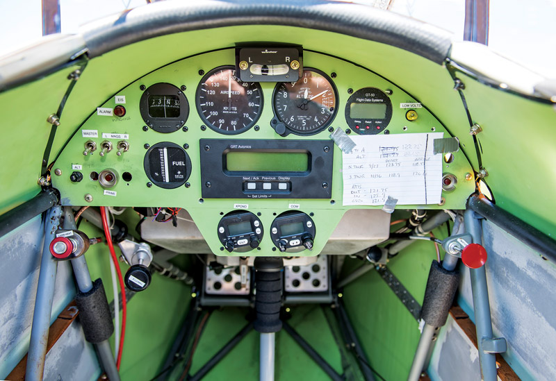
The panel is a work in progress. The OSH arrival notes remained in place during AirVenture 2016 to cover up a big empty hole in the panel.
Instrumentation is strictly day VFR—no lights and no GPS due to our airport underlying the Charlotte Class B airspace. We did install a Trig radio and Mode C transponder. For the trip to Oshkosh last year, John mounted a Stratus wireless receiver on the top wing and strapped an Apple iPad mini to his leg.
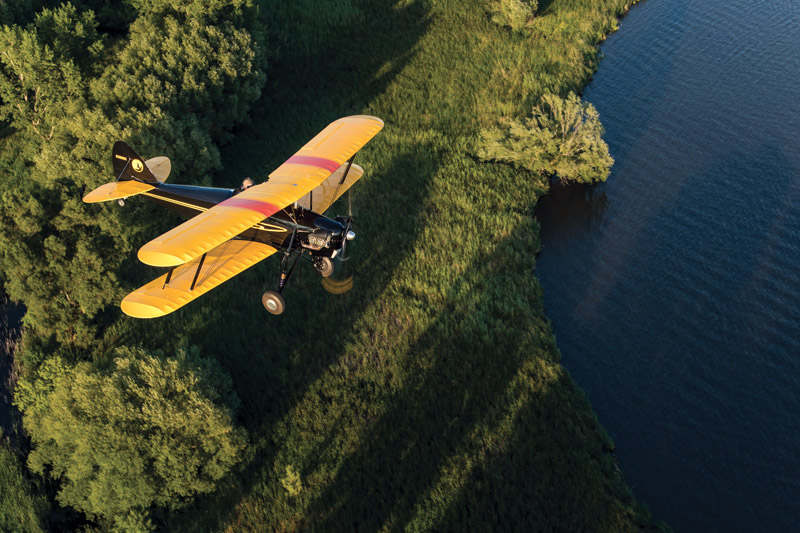
We’re still fine tuning the prop, so top speeds are not final, but with a 76-inch Catto propeller, we’re seeing 82 knots in cruise at 2350 rpm on 5 gph. The stall is at about 40 knots. It’s really comfortable to trim for 65 to 70 knots at 1000 feet agl and enjoy the view.
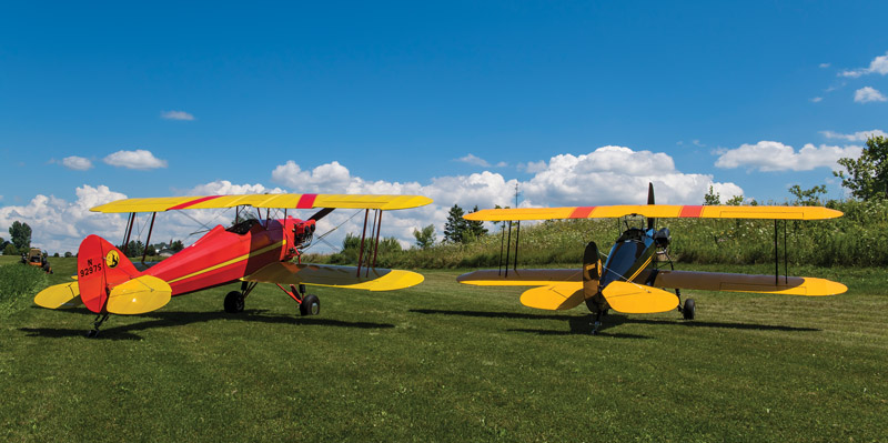
David Novak’s plansbuilt Skyotë (left), was built in the 1990s by Ed Harker. John Roberts’ Tech-Built Skyotë is on the right.
Saving the Design
As with many airplanes, the Skyotë has a faithful following. The Skyotë Type Club website is a great resource for all things Skyotë. Since John documented his Tech-Built Skyotë on his blog many of the faithful watched his progress. When they saw how fast the Tech-Built parts resulted in an airframe (two Tech-Built Skyotës have been started and both have been completed), they started pushing John to sell them his parts.
John resisted for five years. Then in the middle of 2015, he decided to give other builders access to the same precision parts suppliers he used to build his plane. You can read all the details at www.flyteam88.com, but don’t think the process is as simple as making a single phone call and ordering a kit.
First, you’ll need a set of Pete Bartoe’s plans, which are available from Aircraft Spruce.
Next you’ll need to order parts from the vendors listed at flyteam88.com. Keep in mind that the parts require John’s drawings.
John doesn’t sell his drawings—he gives them away, in exchange for a direct donation of $250.00 to the Epworth Children’s Home in Columbia, South Carolina. The purpose of all this effort is to save the Skyotë, while providing funds to a worthy cause.
John also offers builder’s assistance, including a plans supplement manual with over 100 pages and fitting bending services. His email is [email protected].
The concept of applying modern technology to classic, old-school designs could certainly be expanded. Nothing is in the works, but perhaps someday we’ll see a Tech-Built Wittman Tailwind!
Double Trouble

A one-square-foot section from the original Skyotë wing drawing. (Some dimensions have been blanked out because they are proprietary to Pete Bartoe.)
When I first studied the Skyotë construction drawings, I was immediately challenged by the complex airframe geometry and very dense construction drawings. It was a combination that can be deadly to a homebuilder’s dreams. As an example, the photo to the right depicts a one-square-foot section from the original wing drawing. This one section provides most of the information for fabricating eight wing spars, the interplane struts, and more than 30 vital interplane strut-to-spar fittings. The fitting geometry is further complicated by the wing sweep angle, not acknowledged in the drawing.
I also recognized that the Skyotë required the fabrication of over 600 flat metal components, requiring a lifetime behind the drill press, band saw, and sander. Being lazy by nature, I looked for a non-traditional answer to this dilemma and found it in 3D CAD. CAD provided the key to understanding Pete Bartoe’s drawings, plus it allowed the fabrication of hundreds of components by precision waterjet cutting.
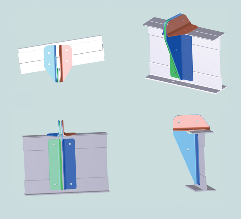
CAD illustration of the four individual parts required for a typical interplane strut cluster.
I was able to perfect virtual models of each component and test fit everything in assembly before cutting a single piece of metal. It took many iterations before this was achieved, but it is certainly better done in “virtual model space” versus real shop space!
The payoff for the CAD work begins with a true understanding of the details of the complex Skyotë design and ends with piles of precision matched-hole components from the waterjet cutter. No layout, no drilling, no sawing, no sanding—just a perfect fit that’s ready to be Clecoed all together. Yippee!
Unlike many computer-generated projects that will fly “next year,” there are now two flying Tech-Built Skyotës, which served as the test beds for all of the CAD-modeled components. Rumor has it that one of them was awarded a Bronze Lindy at AirVenture 2016!

Actual matched-hole Tech-Built components produced from John’s CAD files.
I don’t want to be in business, but I have decided to share this work, including access to Tech-Built component suppliers, with other Skyotë plans owners in exchange for a direct charitable donation to a worthy cause: Epworth Children’s Home of Columbia, South Carolina (www.epworthchildrenshome.org).
Tech-Built components for the entire airframe, including wings, fuse and tail feathers are now available to Skyotë plans owners. Also, a plans supplement package is available that includes over 100 detail, assembly, and exploded-view drawings. More information is available at www.flyteam88.com.
—John Roberts
Jerry Morris Flies the Skyotë
Jerry Morris has over 20,000 flight hours. He was an Air Force C-130 pilot, flew civilian charter for several years, and then was a captain for Delta Air Lines.
I had an opportunity to fly a Skyotë, and what a blast it was. John Roberts’ airplane won a Bronze Lindy at AirVenture 2016 and is beautiful. Fit and finish is just what you would expect from such an achievement.
I’ve flown quite a few taildraggers, some biplanes, and some aerobatic planes, and was anxious to see how this one compared. Most of my time in the last several years has been in my RV-8, with a smattering of time in other RVs and some Champs—both ends of the spectrum in handling and performance.
Climbing in was really not bad, even for an old guy like me. Left foot in the step on the fuse and swing your right leg up and over, and into the single seat. There is a very sturdy handhold conveniently placed in the center of the upper wing that really helps here. Sliding down in, the cockpit rails are tight, but once settled in, they barely rubbed on my shoulders, and it was really comfortable. The low windscreen proved to be very effective, and the visibility all around was open-cockpit superb. All the controls and switches were very accessible and required no stretching or reaching. Very nice.
The little Continental O-200 had already been run this day, so mags on, throttle cracked, mixture in, and crank away. A couple blades later it was up and running. Everything in the green and off I went.
Visibility was actually pretty good taxiing. Slight S-turning was all that was needed. Toe brakes were hardly needed, and the steering through the rudders was very effective but not twitchy. Runup is standard, and I was ready to go.
The Skyotë is a light plane and even with just 100 hp accelerated quickly. By the time I had the power all the way in, the tail was up and ready to fly. Directional control was not an issue, and I was off. Climbing at 70 brought a solid feel with not too high a pitch attitude and excellent visibility. Once out of the pattern, I went up to a higher altitude to play a little.
This thing turns on a dime. Rudder is required, but not much. I led with just a touch, then aileron, and around we went. Same for rolling out. After just a couple turns, it became second nature. It has very light controls, both roll and pitch, and fingertip pressure is all that’s needed to fly. It was easy to trim with the electric trim on the elevator, but there was not a lot of pitch change to trim out with speed changes.
Slow flight at 60 is easy. With power off and holding the nose up, I started feeling the burble in the low 40s. There was an easy break, and the times I stalled it, it wanted to break ever so slightly to the left. A touch of rudder with center stick, though, and I could keep it level. It was very docile.
Steep turns, wingovers, and hammers are all textbook simple and very honest. All the while I enjoyed the great visibility through the wings that seemed to be placed just right for seeing through.
Back to the pattern with my dancing shoes on. In typical carbureted fashion, carb heat on abeam the numbers. I used 70 on base, and once established on final back to 60 indicated. There’s pretty good drag, so with my usual picture, I carried a tad of power down final. Bleeding off over the numbers in the flare, I three-pointed it at just over 50 indicated. Directional control was great, and visibility just out the side of the cockpit was typical taildragger, with not much over the nose. Carb heat and power in, and off I went again.
Next I tried a wheel landing. Same pattern with just a tad of power to keep the speed up for the touchdown. John’s gear is forgiving and wheelies will be simple with just a few tries. Visibility is great with the tail up, and the rudder is very effective. I went up one more time to the final landing, which was basically a repeat of the first. It three-points very nicely and tracks true down the runway with minimal rudder required. Touching down around 50 produces a nice short landing roll, then back to the barn I went, wearing a big grin.
This little ship is a joy to fly, with fingertip controls that are well balanced. Stable in pitch and roll, it didn’t wander around while I was enjoying the view. And what a view! Flying wires and wings were everywhere, but they were easy to see through. In steep turns, looking behind the top wing gives a great view. On the ground, it’s very honest with pretty good visibility. This is the type of plane that’s made for early-morning or late-afternoon jaunts in the country. And, it’s rumored to do great aerobatics.
Thanks so much to John for letting me fly his pride and joy.
—Jerry Morris


