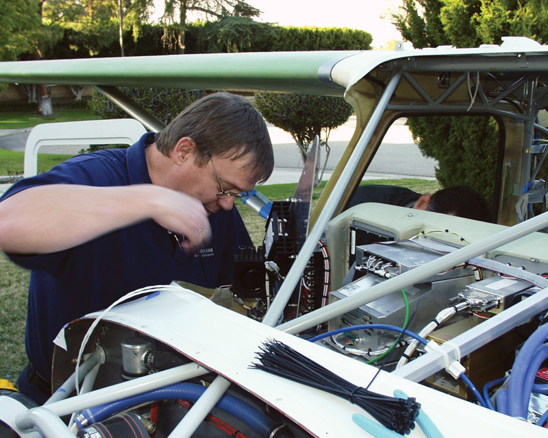
Martin Elshire, now retired from Aerotronics, installs a sub-panel in a GlaStar under construction. Note the neat bundling of the wires behind the instrument panel. Those blue hoses in the lower right are vacuum hoses, revealing the age of this project.
Aircraft electrical is a big topic that will take more than one article to cover. It ranges from batteries and charging systems to lighting and engine sensors, then on to avionics and more. We will start with the basics and go from there. But before we get started, I would like to point you toward two publications that are going to provide you with much more information than I can cover in a few articles. I suggest that anyone who is getting ready to wire their airplane project get one or both of these books before getting started.
The first book I recommend is Bob Nuckolls’ The Aeroelectric Connection. It covers a lot of electrical theory but is still readable by someone who is not coming into the process with a lot of electrical knowledge. This book covers backup electrical systems very well. In this age of all-electric panels and electronic ignition systems, this is a very important topic to most builders. The book can be downloaded for no cost, or a paperback version can be purchased at the same site.
The other book, one that comes highly recommended by Dick Kohler, the main electrical instructor for the EAA Sportair Workshops, is Marc Ausman’s Aircraft Wiring Guide. The book is available in paper or E-book format.
It is also worth mentioning that the FAA’s AC43.13-1B publication has a lot of good information about aircraft electrical wiring. You should already have this book if you are getting ready to wire your plane.
Wire Selection
As many readers know, I am a big fan of using aircraft hardware for aircraft building and maintenance. I feel the same way about aircraft wiring. Use aircraft electrical wire to wire your plane throughout. Do not use hardware store wire for anything in your airplane. The reason does not lie with the wire but with the insulation. Hardware store wire typically comes with PVC insulation that will emit toxic fumes when it burns. The last thing you need when your electrical system goes up in smoke is to have that smoke be lethal.
Wire size can be calculated based on the load and the length of the wire using tables in AC43.13-1B or either of the books previously mentioned. It looks complicated, but once you get the hang of it, the answer comes fairly easily. I usually won’t use wire smaller than 20 or 22 gauge unless it is terminating in a D-sub pin, because very small wires just seem to be too fragile for most things, plus the minimum wire size for most other connectors is 22 gauge. The weight saved by going smaller just isn’t worth the bother, in my opinion.

D-sub pins go on much better with a special crimper made for them. You may see some for as much as $300, but it is not necessary to spend more than $50 to get an adequate tool.
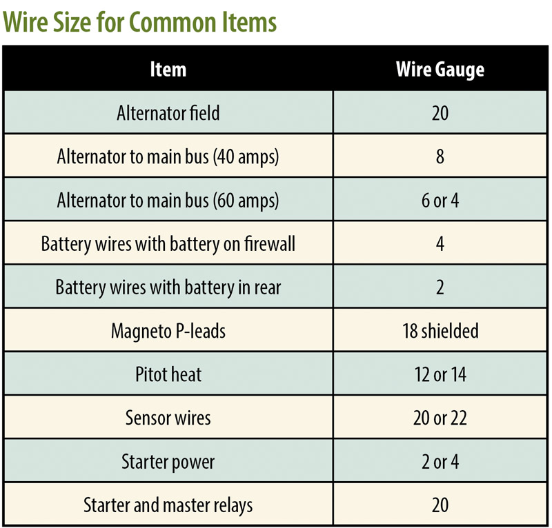
When it comes to battery and starter wires, I recommend 4 gauge wire if the battery is mounted on the firewall, even though the standard wire charts do not. For batteries mounted farther away I recommend 2 gauge wire in line with standard wire charts. In my experience 4 gauge wire works fine when runs are very short, and it saves weight and cost.
Above is a table I put together to show typical wire sizes. These should serve only as a basic guideline. Verify all current requirements and wire sizes with the manufacturer of each item.
Terminations and Connections
Wires will almost always terminate into some sort of connector. Battery cables and power feeds from alternators will end in loop connectors that are either crimped or soldered on, with crimps being preferred. Wires to navigation lights and landing lights will typically end at Molex connectors so the lights can be easily removed and replaced. Avionics wires usually end with a D-sub pin (male or female) that will go into a multi-pin connector of some sort.
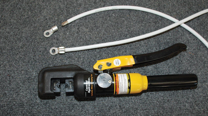
A hydraulic crimper, from Harbor Freight, is the best way to crimp large connectors for 2- to 8-gauge wires. This is a nice tool for an EAA chapter to buy and share, since it will not get a lot of use by any one person.
The preferred method of attaching wires to connectors in most cases is with a crimp. There are exceptions, but this is the general rule because soldering is harder to do well, and solder can wick up wires and make them more susceptible to breaking under vibration. Of course, different wires and connectors will require different crimpers. A 2 gauge battery wire will need a hydraulic crimper. Smaller loop and FASTON connectors are best applied with smaller, ratchet-type crimpers. D-sub pins need their own special crimpers to be properly secured. This means you will need to buy or borrow some special tools to do your wiring properly. Fortunately, these crimpers are not terribly expensive if you shop around.
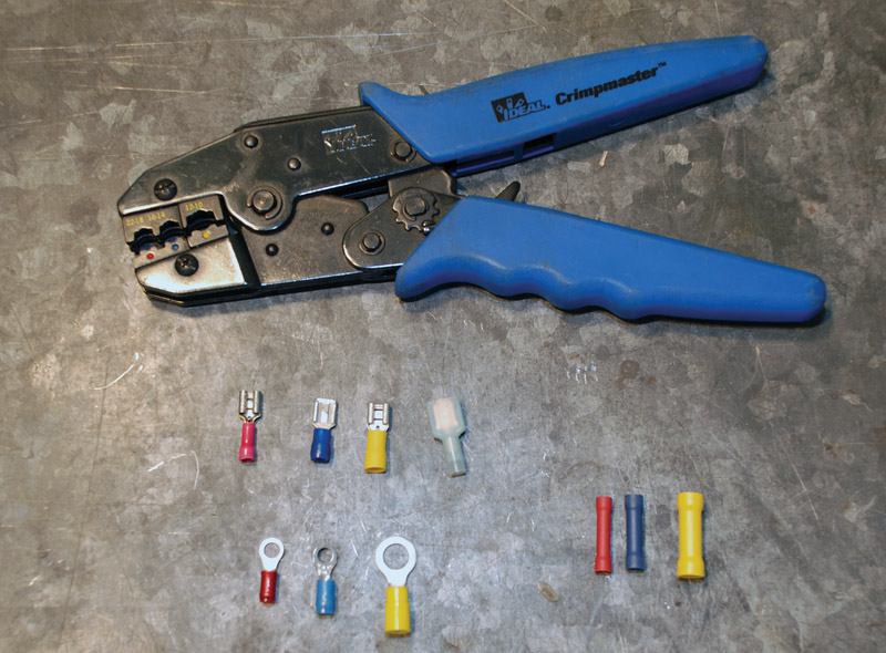
Ratchet crimpers are the way to go for wires sizes from 10 to 22 gauge. The ratchet feature gives you much better control of the crimp than less expensive hand-squeeze crimpers. B&C has these for $45, and you can change the jaws to also crimp coaxial cable without buying another tool.
Harbor Freight has a very good deal on a hydraulic crimper that will make short work of even 2 gauge wire connectors. Many sources such as B&C Specialty Products (the same people who make the starters and alternators) or Aircraft Spruce have ratchet-type crimpers for connectors ranging from 22 to 10 gauge wires. B&C is the place to go for D-sub crimpers, but many electronics vendors also carry them. Just be sure not to buy the $300 version, which is completely unnecessary.
In all cases, be sure to get aircraft-quality connectors that are rated for the wire size and current load you are working with.
Soldering
As a general rule, crimped connections are preferred over soldered connections whenever possible. This is because soldering correctly is more difficult than crimping, and because solder can flow up a heated wire for some distance from the connection, thereby turning a flexible, stranded wire into a solid wire that is much more prone to breaking. That said, there are times when soldering is the best solution to a particular problem.
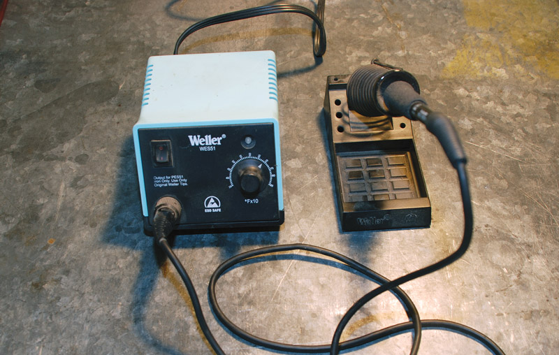
A quality soldering iron such as this Weller unit with variable power adjustment is a good choice if you have much soldering to do on your project. Be sure to get someone to show you how to make a good soldered joint. If someone is not available, at least be sure to look at the EAA Hints for Homebuilders video on soldering.
The art of soldering is worth its own article, but we can cover a few key points. Never use acid core solder for electrical tasks. Always remember that solder travels towards heat, thus the idea is to heat up the spot where you want to solder to go rather than try to heat up the solder itself. If the part you are soldering is not hot, the joint you make will be cold and likely to fail. A soldering iron with a temperature adjustment is best for a good soldering job on different sized connectors. One size does not fit all situations. For example, if you are determined to solder the ends on your battery cables, you are going to need a really big soldering iron.
No amount of words will replace a little hands-on experience soldering. Get some help from someone who knows what they are doing, and you will be able to make good soldered joints with a little practice. However, your first choice should always be to find a way to crimp the connector rather than solder it if you can.
Heat Shrink
Heat shrink tubing is a plastic material that you can slip over a wire or connector and then shrink it to a tight fit by applying heat to it. It comes in many colors and sizes to fit different wire sizes and connectors. It is very handy for providing insulation over uninsulated connectors or soldered wire splices to name a few. It can also provide extra support for a connection where there is likely to be a lot of vibration or movement. The downside to its use is that it can trap moisture in a connection and contribute to possible corrosion at that point. Because of this, its indiscriminate use should be discouraged, but it has its place.
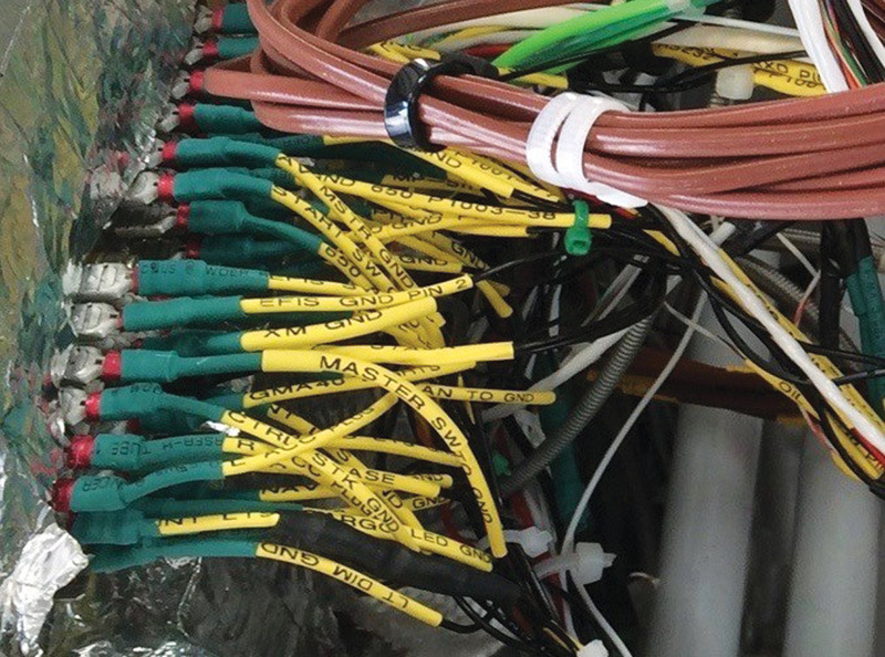
RV builder Rick Weiss made extensive use of heat shrink labels in his project. This should greatly ease tracing down electrical problems if he has any later. These wires are all connected to a large ground bus, in line with Bob Nuckolls’ recommendation. The FASTON connectors make installation quick and easy. (Photo: Rick Weiss)
I have seen people use various devices to apply heat to heat shrink tubing, including cigarette lighters and matches. However, a heat gun is the best and safest way to apply heat, and they are quite inexpensive, sometimes being as low as $10 at Harbor Freight. In some cases silicone repair tape may be a suitable alternative, but it is awkward to use with small wires.
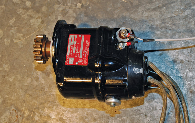
Here is a P-lead installed on a Slick magneto. It is made by stripping the insulation off and separating the shield from the inner wire. The rest is just a matter of applying heat shrink tubing and some loop connectors.
Labeling
For some reason, almost all wires used in aviation are white, making it very difficult to trace a wire from point to point when it is bundled with a bunch of other white wires. Colored aviation wire is made, but it can get very expensive to buy several different colored rolls of wire in different sizes if you are only building one plane. During construction, this isn’t usually that big of a problem, but later it can be very tedious to try and track down a problem. Fortunately, a number of companies offer label makers that will print text onto heat shrink tubing. There are also wire labelers that print onto adhesive backed labels, but I would consider them less useful because they are less durable than heat shrink labels. These labels are not a must-have thing so much as a convenience, but there are places where labels can be helpful. A web search will turn up a number of options for your consideration.
Grounding
Grounding is oftentimes taken for granted when wiring a plane, but the connection to ground is just as important as the connection to power in any circuit. A reliable electrical circuit must have good continuity throughout. Many electrical problems in airplanes, maybe even most problems, can be traced to poor ground connections. For this reason, it is important to get grounding right.

Here is a simple ground bus you can easily make yourself from 1/8-inch by -inch copper stock. It is best to use brass screws and bronze lock washers for this installation.
Bob Nuckolls has popularized the concept of a ground bus, a point at which all items are grounded. Rather than using the airframe for a ground conductor, every device is wired back to the ground bus, bringing all grounds to a single point that is then connected to the negative terminal of the battery. Such an arrangement is mandatory in a composite airplane, but it also has advantages in other types of aircraft. It has become common practice for companies that put together instrument panels to ground to a ground bus, but the wider application of the practice to the entire airplane is not universally embraced. The downside is that it adds wire and thus weight to the plane. However, in my opinion, this cost is outweighed by the benefit.
Many engine sensor problems can be traced to poor grounding. A ground wire from the engine to the battery eliminates points of potential discontinuity or increased resistance at the connections from the ground strap to the motor mount and the motor mount to the rest of the airframe, and finally the connection from the airframe to the negative terminal of the battery. Sensors that work with very low current and low voltage cannot maintain accuracy if there is not a solid, reliable, low-resistance connection to ground.
There is no doubt that airplanes have been flying for a very long time without ground buses, but there is also no denying that those same planes have had their share of ground-related electrical problems for just as long. The ground bus is a step toward greater reliability that is worth your consideration.

Organizing all of your electrical tools and parts in a cart makes it easy to position everything you need to wire your plane close to the work, and it makes it easy to find things later. Harbor Freight is a great source for these carts at a reasonable price.
Shielding
Some wires need to be shielded to minimize electrical interference with other electrical items such as avionics, headsets, and intercom systems. Magneto P-leads are prime examples of wires that need shielding. Leads to strobe lights are another. In any case, whenever a component manufacturer recommends using shielded wire, it is a good idea to heed their advice.
The rule is to only attach one end of a wire shield to ground. The preferred point to do so is at the source of power, although this is not a hard and fast rule. For example, many people choose to ground their P-lead shield at the magneto instead of at the ignition switch as a matter of convenience. Both ways produce good results. There may also be cases in which both ends of the shield are connected in certain avionics installations. Be sure to follow the recommendation of the manufacturer in such cases.
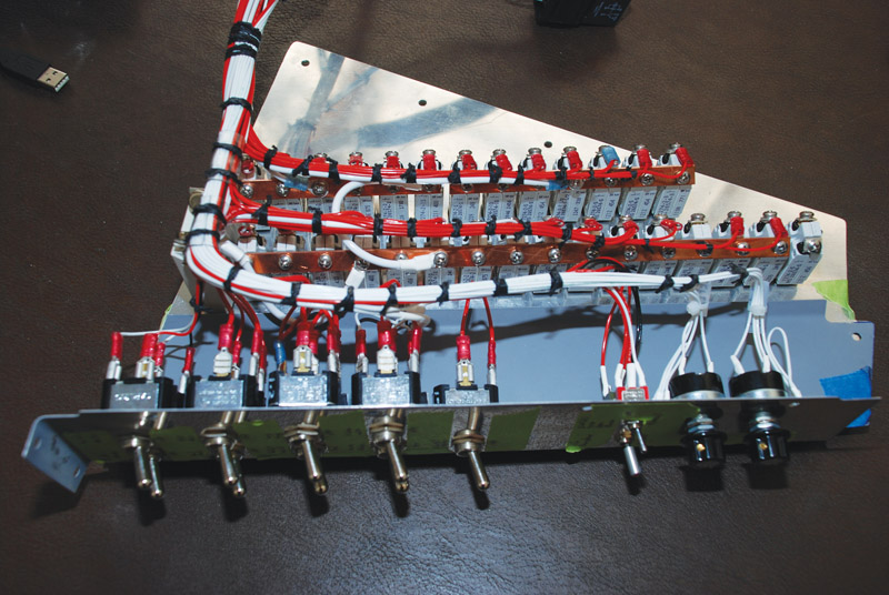
Here is a nicely assembled switch and breaker panel set for installation in an RV-8. Note how the wires are neatly bundled and laced up in a very professional way. You can do this kind of work, too, if you take the time.
Bundling and Securing Wires
Neatness counts when it comes time to sort out wiring problems. A rat’s nest of wires behind an instrument panel can discourage even the most ardent electrical technician, not to mention you if you end up with the job. The best panel builders and aviation electricians will neatly bundle and secure wires wherever they can, often using lacing every few inches. For those who are less particular, zip ties will do the job. The point is to prevent wires from becoming tangled, chafing, or interfering with other systems by moving around excessively.
In the engine compartment, secure wires can be firmly held away from hot exhaust systems or moving parts where they can become easily damaged. Wires that are at all close to heat sources can be protected with firesleeve just as fuel lines are. Of course, don’t forget to allow enough slack in wires that go from the airframe to the engine to allow for engine movement. Elsewhere in the airframe, it may be prudent to run wires in lightweight plastic electrical conduit to prevent chafing. A good example of that is wires that go out through the wings to nav lights and strobes.
More to Come
This time we have just looked at the basics of electrical wiring and connectors. Next time we will examine subjects such as the requirement list, sizing alternators and batteries, wiring diagrams, backup batteries, overvoltage protection, and circuit breakers.


