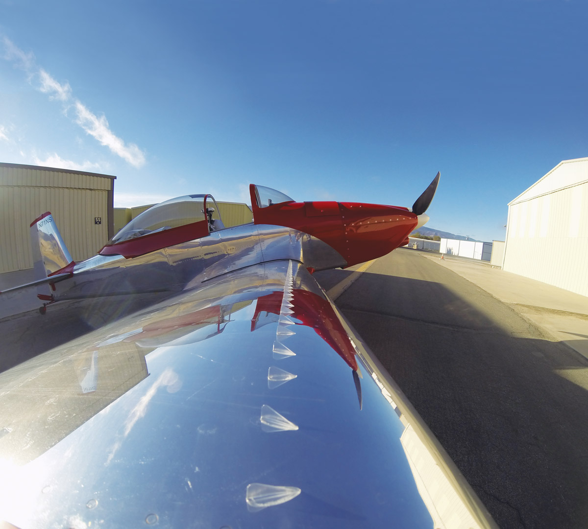
There I was, at the annual Van’s Aircraft Homecoming Fly-In, a tasty local beer in one hand and a fistful of raffle tickets in the other. By night’s end the raffle tickets had transformed into a set of STOLSPEED vortex generators (www.stolspeed.com). So while I was perfectly happy with my RV-8’s handling qualities, installing the vortex generators (VGs) seemed like a great opportunity for education and recreation.
The generic list of benefits of VGs claimed by manufacturers is extensive: lower stall speed, lower liftoff speed, shorter takeoff and landing, improved controllability and safety, easier landing, crisper aileron response, less tendency to drop a wing in a stall, a mush rather than a break at stall, easier and quicker stall recovery, and more elevator control at low airspeed—all with little to no loss of cruise speed.
They are designed to do this by adding turbulence and energy to the boundary layer, so that the flow stays attached at higher angles of attack (AoA). The first order effect is that the slope of coefficient of lift (CL) versus AoA remains constant, but the stall AoA is increased. This higher stall AoA results in a higher CL at the stall. The higher CL means that Lift = Weight can be achieved with lower velocity (lower stall speed). I set out to put the various VG claims to the test on my specific aircraft.
CAPTA line made with a Sharpie or electrical tape was used to keep the VGs in a straight line.ION
Installing the VGs
STOLSPEED VGs are made in Australia and come neatly packaged with laser-cut adhesive and templates. At the time of writing, the VGs were priced at $97 USD (wing kit), $65 USD (tail kit) with postage $7 USD (worldwide).
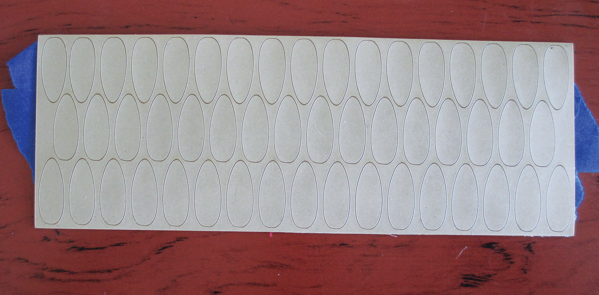
Instructions for fitting were downloaded from the company website. The VGs were made from a flexible UV-resistant polycarbonate. The base was oval shaped, 1 inch long, and 0.4 inch wide. They were 0.4 inch high with a sweep of 27 and had rounded corners. The bases were also slightly curved to allow a better fit to the aerodynamic shape of a wing. If they are to be fitted to a flat surface, they can be easily flattened by a few strokes on a sheet of sandpaper lying on a flat surface.
The VGs are made from flexible UV-resistant polycarbonate and come in adhesive-backed sheets.
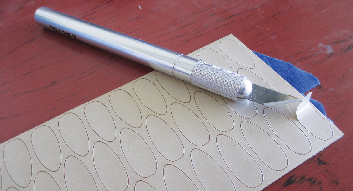
An X-Acto knife was used to peel back the covering of the pre-cut adhesive sheets.
There were 120 VGs in the wing kit and 80 in the tail kit. Mounting the VGs was quite easy and simple. Excluding paint, it would be a morning’s work to apply the VGs to the tail and wing of an RV-8.
The first step was to clean the surfaces of the wing and the bases of the VGs. Next was to peel back the covering of the pre-cut adhesive sheets; an X-Acto knife worked well for this. The VGs were firmly pressed onto the adhesive layer then removed from the sheet, taking the adhesive layer with them.
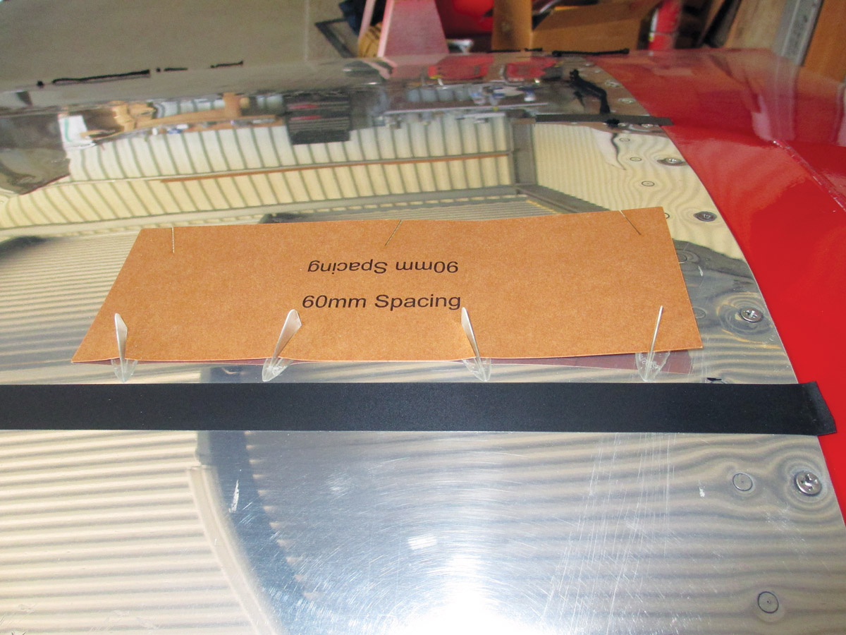
A template was used to keep the VGs spaced evenly.
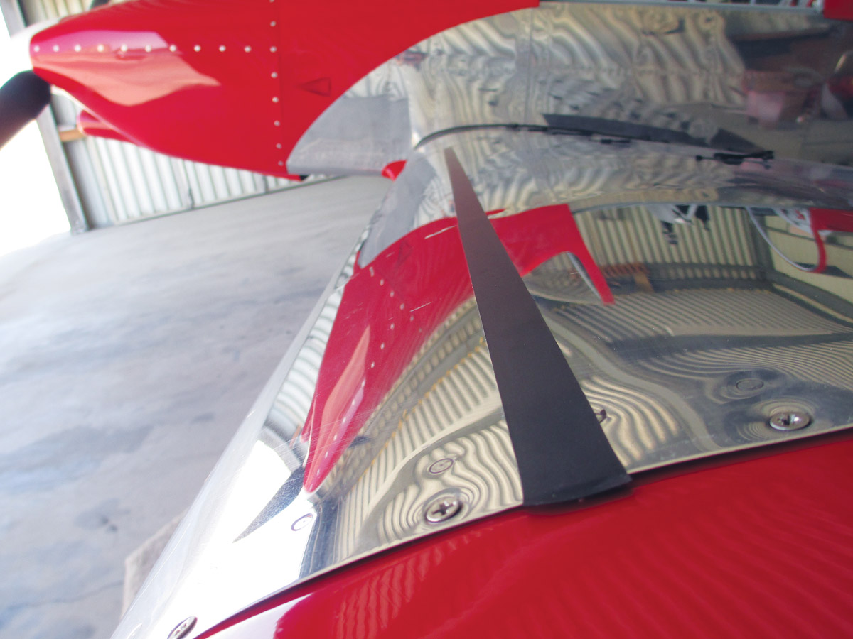
There were three templates supplied: 1.2 inch (30 mm) spacing for the horizontal tail, 2.4 inches (60mm) spacing for the wing in front of the ailerons, and 3.5 inches (90mm) spacing in front of the flaps. The template places the VGs at 18 to the chord. The instructions advise placing the VGs on the bottom of the horizontal tail 4 inches (100mm) in front of the elevator hinge line. For the wing it was suggested to place them 8-10% of the chord from the leading edge. The RV-8 wing has a chord of 58.5 inches; I placed the front of the VGs 4.75 inches aft of the leading edge where a rivet line made for convenient marking. This put the front of the VG at 8.1% and the rear of the VG at 9.8% of the wing chord. A line made with a Sharpie or electrical tape was used to keep the VGs in a straight line.
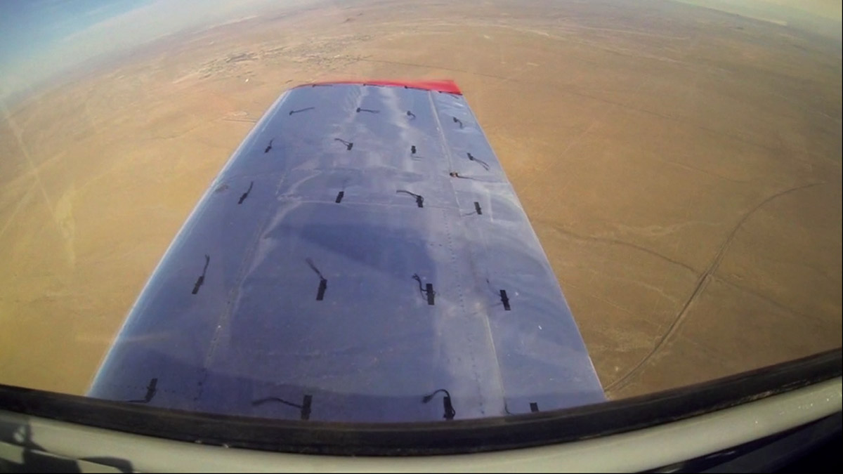
Tufts for visualizing airflow were made from 6-inch lengths of black wool attached with electrical tape. Chordwise I attached them at 25%, 50% and 75% on the wing and also in the middle of the ailerons and flaps. Spanwise I attached them every second wing rib.
VGs installed on the bottom of the horizontal stabilizer.
Once the position of a tuft had been determined, I taped the tuft to the wing with the long end toward the leading edge. Then I folded the long end back over the tape. Finally, I used a second piece of tape to hold the tuft firmly in place.
A GoPro camera was used to record the tufts. I tufted both wings even though I only videoed one. This was to prevent any potential asymmetric behavior caused by tufting only one wing. Be careful applying tufts to a laminar flow wing; this seemingly small change can result in large and adverse changes in climb rate, stall speed, and stall characteristics.
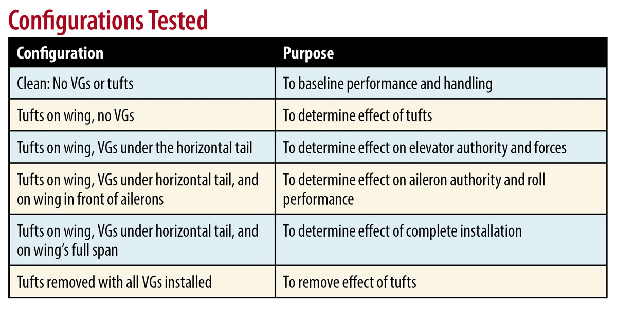
Configurations Tested
I did a series of six flights, each of about one hour duration. The configurations I flew are shown in the table below.
When I constructed my plane, I installed string potentiometers attached to the controls that are read by the engine monitor of the Dynon SkyView EFIS. This allowed me to generate the plots of control positions versus airspeed, AoA, and pitch and roll attitudes that accompany this article.
Flight Profile
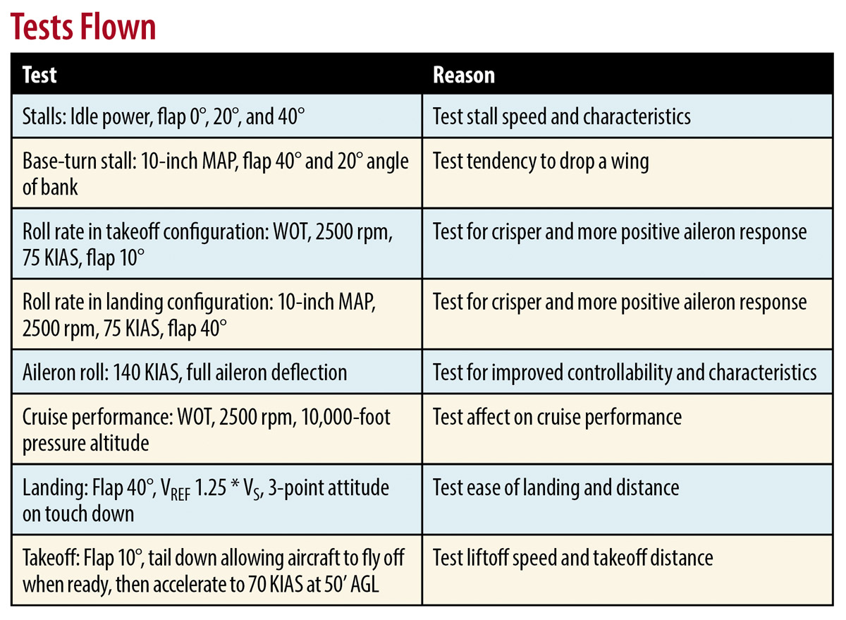
Each flight followed the same profile. I took off with 25 gallons of fuel, which put the start weight at 1496 pounds (mid) and cg at 79.8 inches (forward). I flew each flight in the same sequence and at the same pressure altitudes. This was to minimize the variations in ambient conditions between different configurations. The tests I flew are shown in the Tests Flown table.
Airflow Characteristics
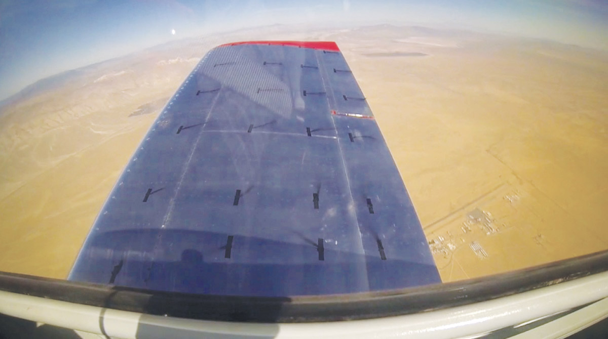
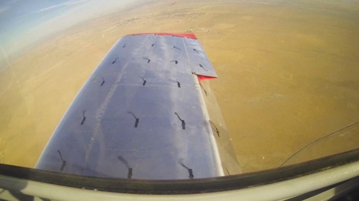
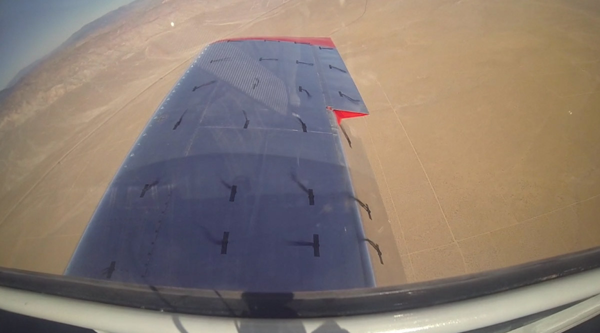
To allow visualization of the airflow in different configurations of flap and VGs, I tufted each wing. As AoA increases, flow over the RV-8 wing first begins to separate at the inboard trailing edge and then moves diagonally outboard to the tip leading edge.
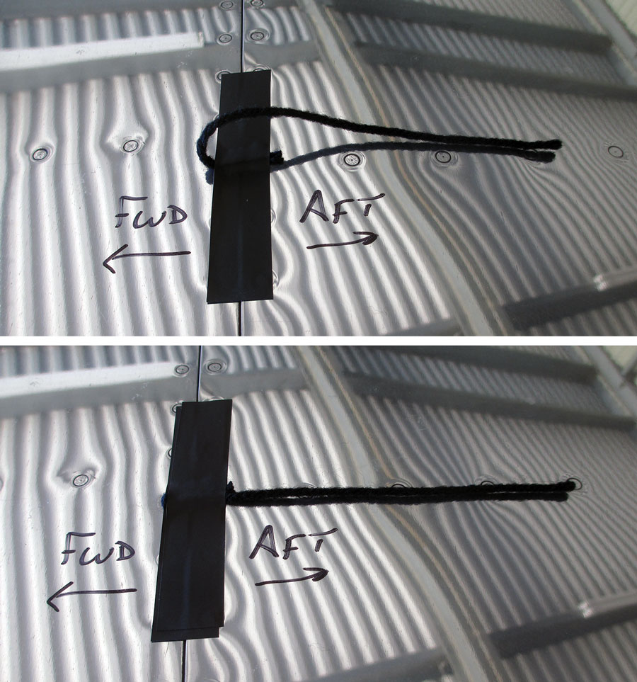
Tufts were installed with a single piece of electrical tape and worked fine. Doubling them over helps them stay attached at high speed, but below 200 knots it probably makes no difference.
With flap settings greater than 10, the airflow over the top of the flaps was separated. Adding VGs in front of the flap did not cause the airflow to remain attached to the flaps. VGs in front of the ailerons did keep airflow attached to the outboard 1/4-span of the wing during stalls when the inboard 3/4-span was separated.
In cruise without VGs the tufts would lie close to the wing. Placing VGs in front of the ailerons and flaps caused the tufts at 25% chord to rise up approximately 1 inch, while the tufts at 50% and 75% would remain close to the wing. This change in flow may be responsible for the change in cruise speed that I saw.
Stall with flaps up, no VGs.
Stall with flaps up and VGs.
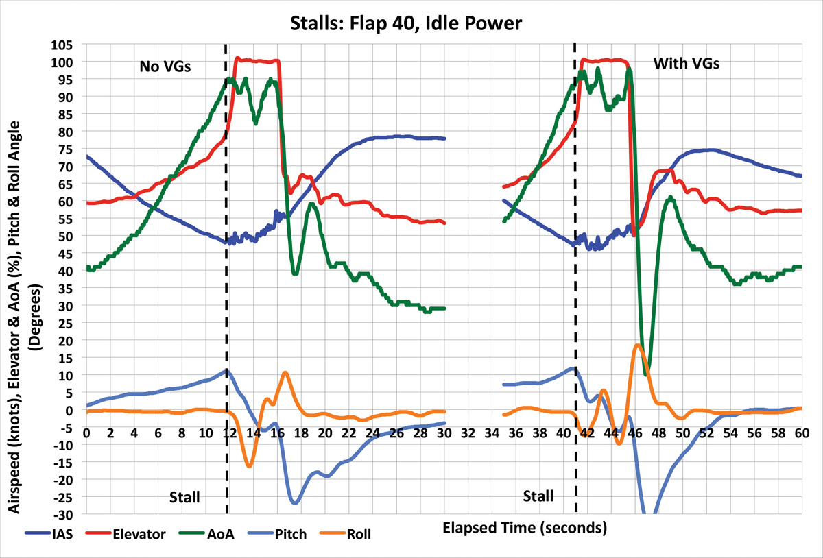
Stall with flaps at 40, no VGs.
Stall with flaps at 40 with VGs.
VGs on the bottom of the horizontal tail reduced the stick force per G by about one-third. The stick forces per G were not as light as being at the very aft cg limit, but the reduction was still noticeable.
Stall Speed
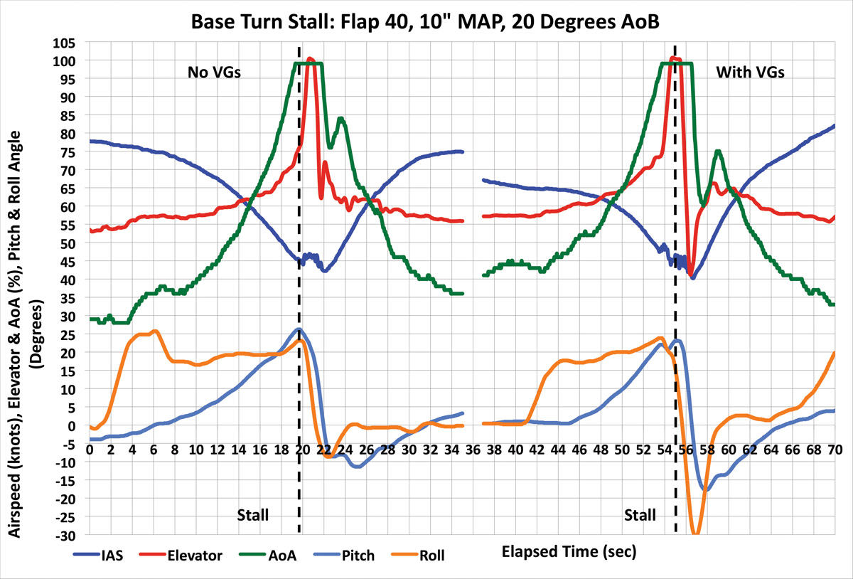
Stalls were done with the throttle at idle, propeller full forward, and elevator aft to achieve approximately 1-knot-per-second airspeed reduction. After the nose dropped, full aft stick was applied and held for two seconds to capture post-stall behavior. I defined the stall as the point where either pitch attitude or AoA began to reduce while the stick was still moving aft. In all cases tested the peak AoA was achieved before running out of elevator travel. The wing, not the elevator, limits stall speed in this RV-8. The addition of VGs under the horizontal tail did not reduce the stall speed. VGs on the leading edge visibly altered the airflow over the wing, but this did not translate into lower stall speeds.
The horizontal axis of the stall graphs is time in seconds. I spliced together results from a stall without VGs followed by a stall with VGs, hence the small gap in data.
On the vertical axis of the stall graphs, the airspeed is in dark blue. The elevator position is in red, with 0% being full forward and 100% being full aft. AoA is in dark green, 0% is the no-lift AoA, and 100% represents the stalling AoA with 40 flap.
Pitch and roll angles are shown at the bottom, with positive values representing nose-up and right bank angles. Negative values represent nose-down pitch and left bank angles.

Post Stall Behavior
Without VGs the aircraft was quite controllable during stalls. With the stick held fully aft there was a slight wing rock of 5. The pitch attitude oscillated between +15 and +5 as the aircraft stalled and unstalled. Ailerons operated in the normal sense while stalled, although less effectively.
With VGs installed the AoA and pitch attitude reduced before full-aft elevator was reached, so there was still a stall break and not a constant pitch attitude or AoA mushing behavior. The addition of VGs roughly halved the magnitude of roll and pitch oscillations post stall with full aft elevator. You could argue this is an improvement in stall characteristics, but you would only see it if you held the stick full aft for a few seconds after the aircraft had already stalled. If you relaxed the aft stick pressure at stall warning, stall buffet, or as soon as the nose drops, you would not see any difference due to the addition of VGs.
In a coordinated base turn, the normal behavior of my aircraft is for the pitch attitude to drop and to roll toward wings level at the stall with stick full aft, regardless of the initial turn direction. The addition of VGs did not alter these characteristics.
Stall Recovery
In all cases tested, simply relaxing aft stick forces and allowing the elevator to float to the trimmed position resulted in immediate AoA reduction and stall recovery. This stick movement was from 100% (fully aft) to 65% (1.5 inch aft of center), a total distance of 3.5 inches forward. This recovery control input was consistent in all flap and VG configurations. This input was very easy to make and took less than a second, requiring little skill or judgment. The addition of VGs did not improve the ease or time to recover from a stall.
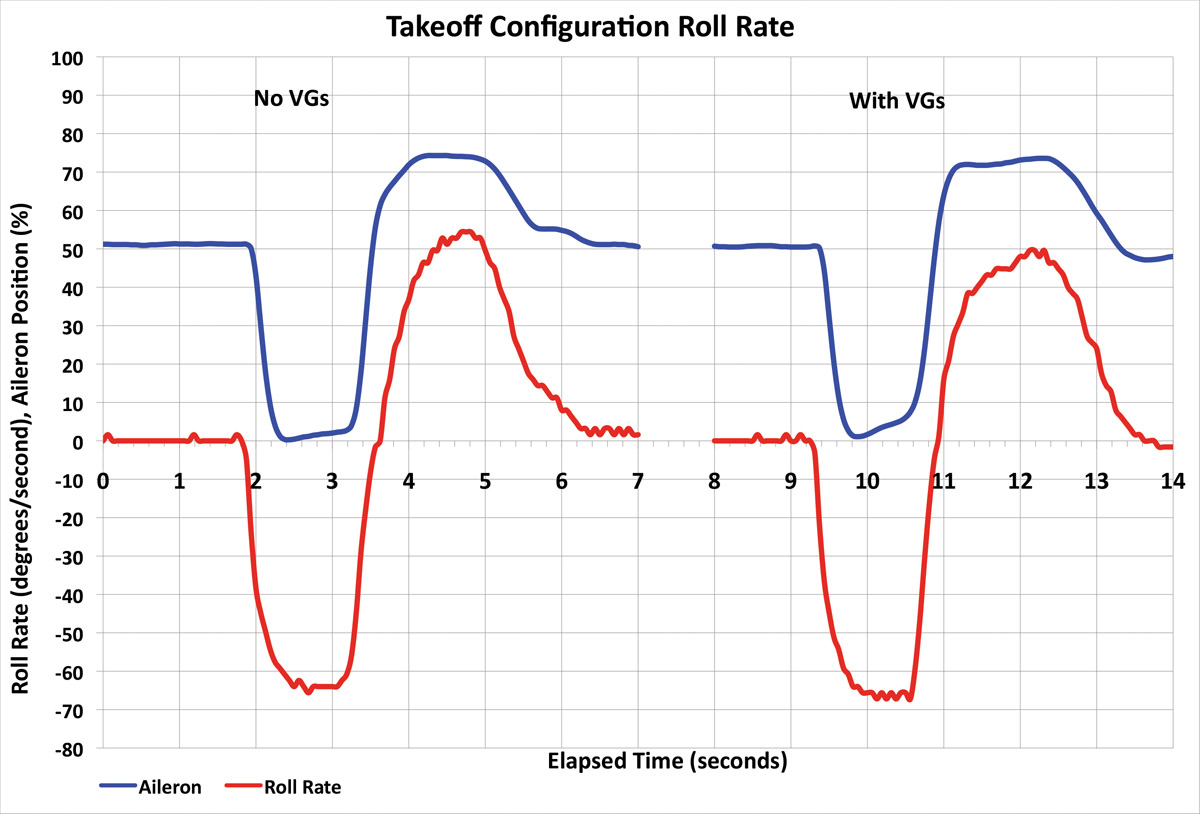
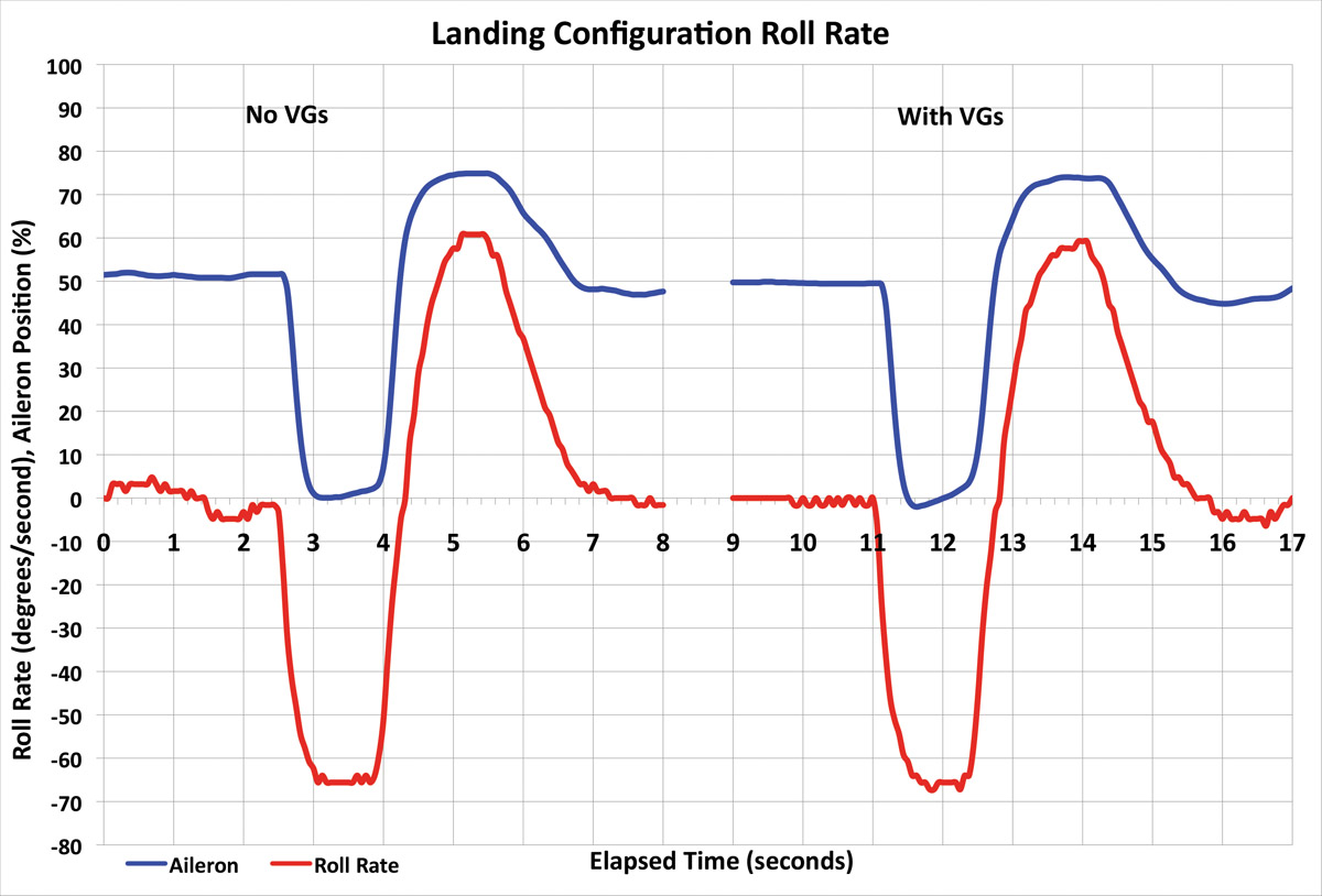
Roll Performance
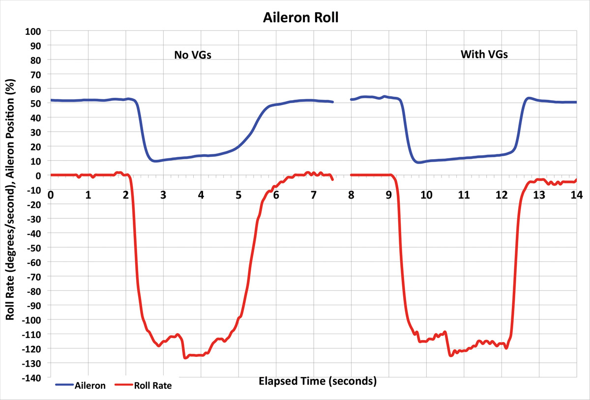
I interpreted the claims of increased slow-speed controllability to mean that the steady-state roll rate for a given lateral stick input was increased. As for the improved characteristics and crisper aileron response, I took that to mean that the steady-state rate was achieved faster (i.e., a shorter roll mode time constant). I conducted rolls using full lateral stick inputs through 90 of bank in the takeoff (WOT, 75 KIAS, Flap 10) and landing (10-inch MAP, 75 KIAS, Flap 40) configurations. I also did aileron rolls at 140 KIAS. Placing VGs in front of the ailerons did not cure the slight oscillation in lateral stick that is felt at full deflection during aileron rolls that is typical in the RV-8. The addition of VGs did not alter the maximum roll rate or reduce the time taken to get to the steady-state roll rate in any configuration tested. On the accompanying graphs the vertical axis is both aileron input and roll rate. Full left aileron is 0%, and 100% corresponds to full right aileron. Negative numbers indicate roll rate to the left and positive numbers indicate roll rate to the right. In the takeoff and landing configurations, it takes approximately 0.7 second to accelerate to the steady-state rate of 65 per second. Aileron roll rates were higher at 125 per second.
Cruise Performance
Cruise performance was tested at 10,000 feet pressure altitude using WOT, 2500 rpm, and sweeping the mixture from ~14 gph (full rich) to ~7.5 gph (50 F LOP) in 1-gph steps. I let the airspeed stabilize for 3 minutes after each mixture change before recording data.
With each addition of tufts and VGs, there was a slight reduction in speed at any given fuel flow. Addition of tufts alone reduced speed by 1 KTAS. Adding the VGs under the horizontal tail reduced speed by an additional 1 KTAS. Placing VGs on the wing leading edge in front of the ailerons cost another 3 KTAS. Completing the VG installation in front of the flaps reduced cruise by another 2 KTAS. Removing the tufts increased the cruise speed by 2 KTAS.
The net effect was a full VG installation reduced the maximum cruise speed by 5 KTAS. On this specific aircraft, installing VGs definitely reduced the cruise speed and made it measurably slower than the clean aircraft. Maximum cruise speed was reduced from 187 KTAS to 182 KTAS (-5 KTAS, -3%).

Takeoff
Takeoff performance was conducted on Runway 24 at California City (L71). The configuration was flaps 10, mixture rich, propeller full forward, brakes held until 2300 rpm, then throttle was briskly applied. The tail was held on the ground until the aircraft flew off in a 3-point attitude at a liftoff speed of 50 KIAS. Previous testing in my aircraft with a differential GPS has shown this to result in the shortest ground and air distances. The fact that the aircraft flies off the ground in the 3-point attitude of 11.5 nose up is indicative of the fact that the wing is not stalled, and video of the wing tufts also confirmed this.
Once airborne, pitch attitude was adjusted to achieve 70 KIAS at 50 feet agl. The ground, air, and total distance to 50 feet was measured using the onboard Dynon GPS. While not as accurate as a differential GPS, the use of airspeed and vertical acceleration allowed distances to be measured accurately enough to identify gross changes. The addition of VGs did not change the liftoff speed or takeoff distances.
One general caution with getting an aircraft with a tractor propeller airborne at the slowest possible speed is that while the elevator and rudder are quite effective, the ailerons are not. My aircraft roll rate at 50 KIAS is half of that at 70 KIAS in the takeoff configuration. If you get a significant roll disturbance close to the ground at low speed, you might not have the roll control authority to counter it.
Landing
Landing performance was also conducted on Runway 24 at L71. Approaches were flown with flap 40 using the PAPI for glideslope guidance and a VREF of 64 KIAS (1.25 * VSO). The throttle was smoothly reduced to idle starting at ~15 feet agl, followed by a flare to land in a 3-point attitude. This resulted in touchdown speeds just above the stall. Moderate braking was used to bring the aircraft to a full stop.
As the addition of VGs did not lower the stall speed, the approach speed also remained constant. In a tailwheel aircraft, the pitch attitude at touchdown is fixed by the geometry of the landing gear (assuming you don’t want to land tail first), which in my aircraft is 11.5 nose up. Even if the VGs did increase the stalling AoA, it would not be an advantage on landing in this aircraft, as it is not stalled in the 3-point attitude. For this reason the landing distance remained constant as well.
Minimizing landing distance by using a slow final approach speed (Van’s recommends a faster VREF of 1.4 * VSO) resulted in flying in a region of negative flight path stability, which required very close attention to airspeed on final (controlled with pitch attitude) and rate of descent (controlled with power). A noticeable difference during landing with VGs installed was the longer grace period between flare and touchdown. Without VGs, if I flare and hold off a few inches above the runway, the aircraft tends to abruptly transition from flying to falling. With VGs the aircraft tended to settle more gently and provided a greater time to finesse the landing attitude. This change is something that the VG manufacturer highlights as a major improvement.
Living with VGs
Here are some additional things to consider when mounting VGs to your aircraft: These specific VGs are not fuel tolerant, so some care needs to be taken when refueling. The addition of VGs makes cleaning the area around them slightly more difficult. These specific VGs had rounded corners and were soft and pliable, so there was no danger of injury. Aesthetics are in the eye of the beholder, and I am sure three pilots would have four opinions on how they look.
Safety
While you may hope that adding VGs, or any other significant aerodynamic modification, will improve the characteristics of your aircraft, you should be prepared for surprises. Pay particular attention to the skid ball when stalling. If you hold the aircraft in a stall and manipulate the ailerons and/or rudder, be prepared for the aircraft to depart. Practice spins before you embark on a modification program that will likely alter the stall characteristics. Build-up to fully stalling the aircraft; begin by recovering at stall warning, then at the buffet, then immediately when the nose drops or when you reach full aft stick. Do any stall testing high enough that you can recover from an unintentional spin. Also consider wearing a parachute and helmet.

Conclusion
The table on the top of this page shows a summary of my test results. It was probably a bit optimistic to expect that all the generic claims of VGs would apply to any specific aircraft, and this is what I found.
In my case, the VGs did not alter the stall speeds. There was a noticeable reduction in post-stall pitch and roll oscillations, but there was no significant improvement in ease or speed of stall recovery. The stick force per G was lightened somewhat. The roll performance of the aircraft was unchanged in any configuration. Cruise performance was reduced. Takeoff and landing distances were not altered. The flare to landing was more forgiving to errors in level-off height.
The fact that the addition of VGs did not vastly improve the RV-8 without any penalty is a testament to its fundamentally sound design. Don’t take these results as a vote against VGs on other aircraft types; with different priorities they could prove to be a very economical and effective improvement.


Thank you for doing this work so thoroughly. I have 25 hrs in my 2nd-hand RV8 and find it very easy to wheel-land solo in all flap configurations, but almost impossible to 3pt, because it’s not done flying the way my Supercub, SuperSTOLL and Maule were. I have not tried tailwheel-1st because it seems impolite on a low-wing with small wheels and no shocks.
She’s 1138# empty with an IO360 and CS prop.
With my 265# buddy in the back, and my 185# up front and 25# in the nose and 20g fuel she’s juuuust inside W&B.
In this mode I can’t keep the tail up when wheel-landing, but 3-pt is workable.
My easiest landings solo are wheelers with about 40# behind the rear seat.
I love VG’s on back-country AC, but I was thinking they’d make solo-wheel-landing even more difficult in the 8.
Your testing makes me think that landing’s wouldn’t change much other than a bit more time between when want’s to quit flying and when she let’s me know.
Thank you for doing this work so thoroughly. I have 25 hrs in my 2nd-hand RV8 and find it very easy to wheel-land solo in all flap configurations, but almost impossible to 3pt, because it’s not done flying the way my Supercub, SuperSTOLL and Maule were. I have not tried tailwheel-1st because it seems impolite on a low-wing with small wheels and no shocks.
She’s 1138# empty with an IO360 and CS prop.
With my 265# buddy in the back, and my 185# up front and 25# in the nose and 20g fuel she’s juuuust inside W&B.
In this mode I can’t keep the tail up when wheel-landing, but 3-pt is workable.
My easiest landings solo are wheelers with about 40# behind the rear seat.
I love VG’s on back-country AC, but I was thinking they’d make solo-wheel-landing even more difficult in the 8.
Your testing makes me think that landing’s wouldn’t change much, so I will resist the urge to try them. Thanks!
G’day Nigel,
I also fitted STOL Speed VG’s to my RV8, using the guide supplied by the manufacturer, John Gilpin. I didn’t have access to any sophisticated testing equipment, and noticed no difference in cruise speeds, but definitely a subtle improvement when landing, right around the time when the aircraft is just about to settle and I’m feeling for the ground. I find my wheeler landings more predictable.