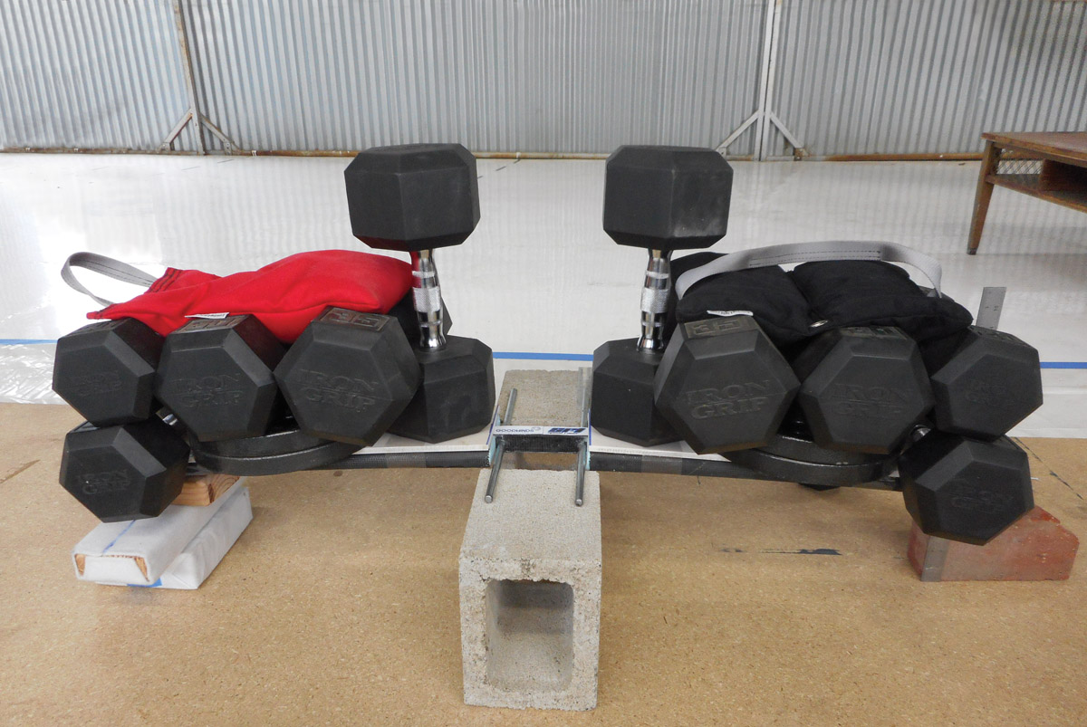
The SR-1 scale spar supporting a load of 380 pounds during a deflection test.
This article continues our series of investigations into testing of materials and construction techniques used on composite aircraft. So far we have looked exclusively at sandwich coupons. However, this article will look at scale model testing, and as such is applicable to any form of construction method—composite, metal, tube, wood—assuming you are able to appropriately scale the dimensions of the constituent materials.
If you’ve been following this series, you know by now that we like to break stuff! And as much as full-scale destructive testing is pretty cool, it’s also expensive and time consuming. I’d prefer to break some coupons or scale models, if possible.
So, scale model testing can provide meaningful results with considerably less investment of money and labor than testing full-scale structures. The basic idea is that material properties—namely, strength and stiffness—have fixed values, and that by applying a scaling factor lambda (λ), the performance of a scale model can be used to model the performance of the full-scale structure. A knock-on benefit is that building a model can allow you to hone your skills and construction strategy on a small project before tackling a larger one.
Stan Hall, an avid sailplane pilot and aviation writer, discussed scale model structural testing in his May/June 1988 Sailplane Homebuilder’s Association article, “The Lesson of Tehachapi and a New Slant on Structural Testing” (p 236 in The Collected Works of Stan Hall, Vol I). If scale testing interests you, I encourage you to read Stan’s article, but the takeaway points are as follows:
- All aspects of the model that see a significant load should be included in the scale model. Failure or inability to do so invalidates that aspect of the model. This does not necessarily invalidate the model as a whole, if one is careful to consider the effect of non-scaling structures.
- The model should be as large as practicable so that errors induced from scaling are minimized. Dimensional errors on a one-tenth-scale model will be ten times larger in the full-scale model, whereas such errors on a half-scale model will only be twice as large. And since lambda is often squared or cubed, such errors can significantly affect the results. Larger scale models will also be easier to source materials for and will probably be easier to construct than smaller models with fiddly details. Half- or quarter-scale (i.e., lambda = 2 or 4) seems to be a good compromise.
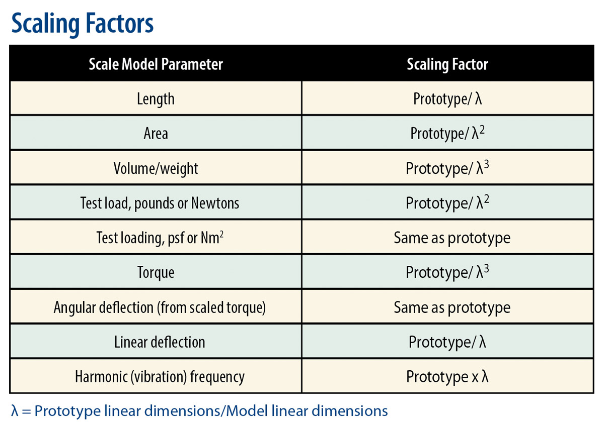
- The scale factor lambda (λ) is established geometrically and factored according to the parameter being tested. Hall provides the scaling factors as seen in the table to the right.
Modeling a Wing Spar
The wing spar of the SR-1 raceplane uses pultruded carbon fiber rods for its cap strips. I generally try to avoid reinventing the wheel, and the pultruded carbon spar is a wheel that has already been worked out. Jim Marske’s work with the Genesis sailplane helped introduce pultrusions to the Experimental aircraft arena, and more recently Bob Kuykendall has successfully used pultrusions in the spar caps of his HP-24 sailplane, for example.
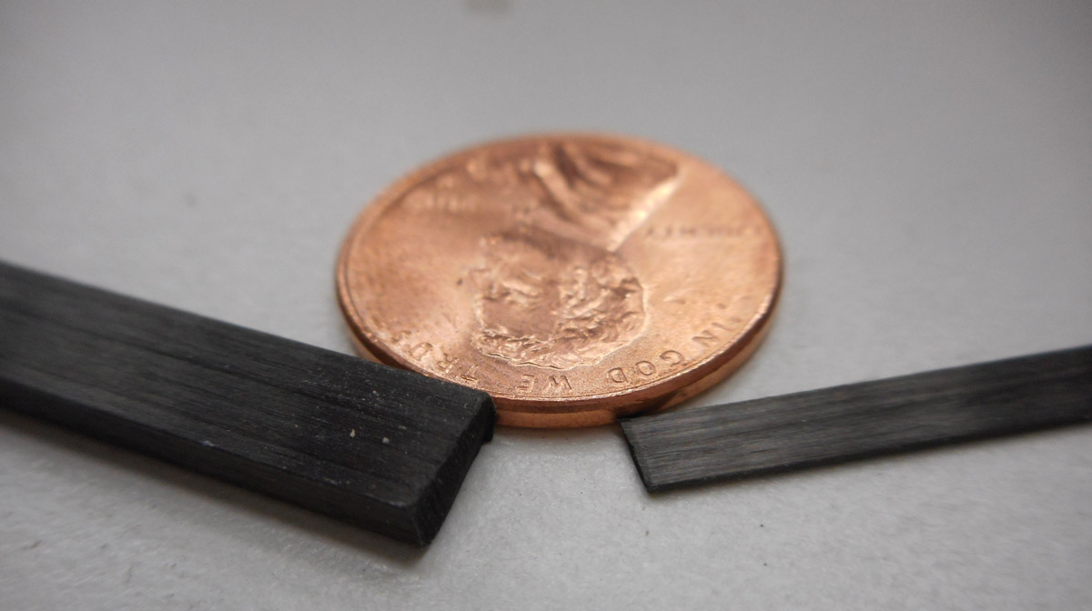
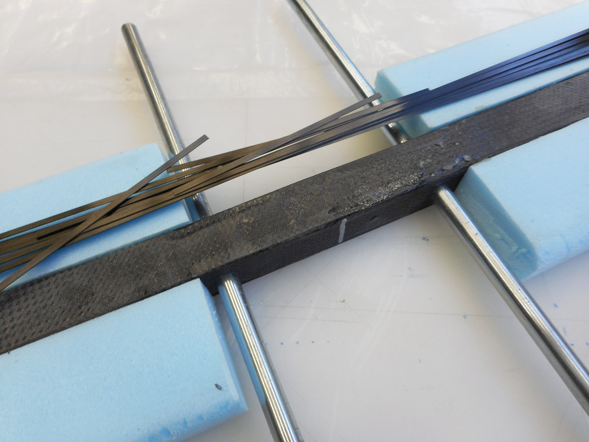
omparison of pultruded carbon used in the full-sized spar with that used in the scale spar. Using a scale factor of 4.25 allowed one small stick to represent exactly two full-sized sticks, making the spar schedule easy to calculate.
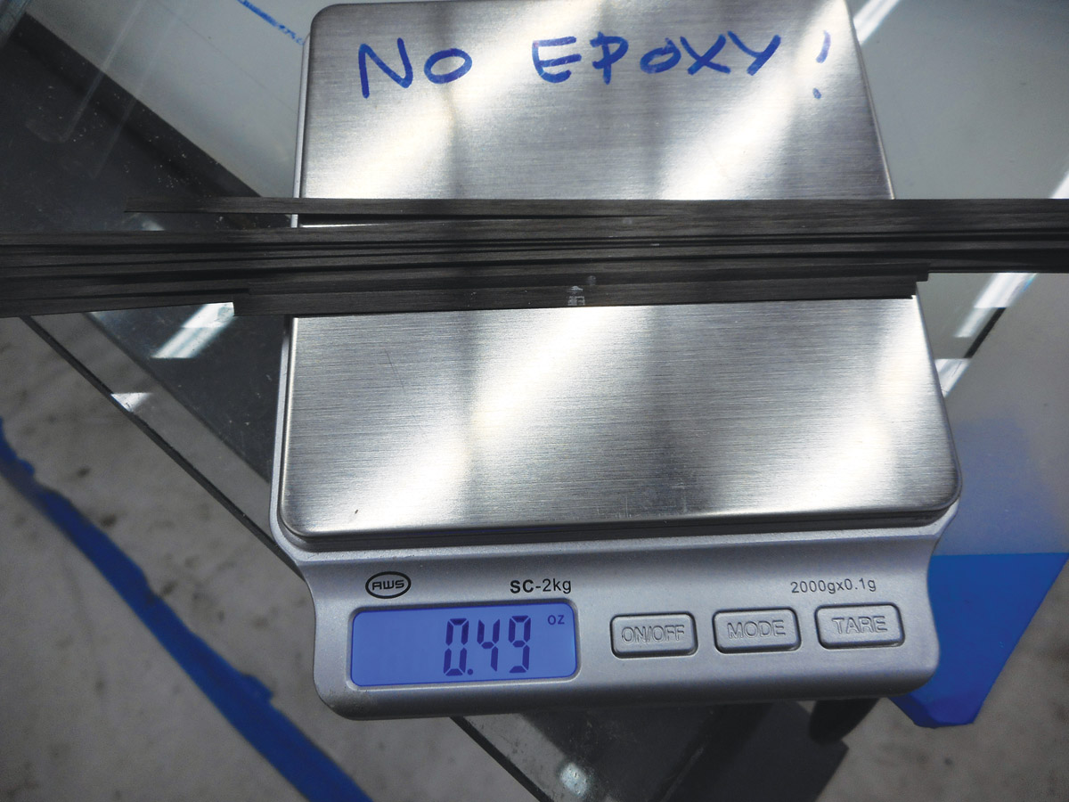
CAPap strip weight was 0.49 ounce per upper and lower cap. A total of 0.98 ounce of pultruded carbon fiber was able to support almost 10,000 times its own weight.TION
Although pultruded carbon has been used in sailplane wings, for whatever reason they are not as common in powered planes. Since a certain amount of engineering comfort is derived from knowing that a particular material or design is common practice, the relative lack of pultruded carbon (as compared to unidirectional fabric, which is more common for making cap strips) pushed me to want to confirm my spar design and construction methods. Although I considered building and testing to failure a full-scale spar, I decided to test a scale spar for deflection (non-destructive) and load (destructive/to failure), followed by a static test to limit load of the real wing later. Since I had already calculated the dimensions of the real spar, scaling was easy. Goodwinds Composites offered to sponsor the SR-1 Project with pultruded carbon for both the scale spar and real spar.
Box spar wrapped with shear web and awaiting cap strips. The blue foam “wings” will be wrapped with bias carbon to provide support for the weights, while the steel bars support the spar during testing.
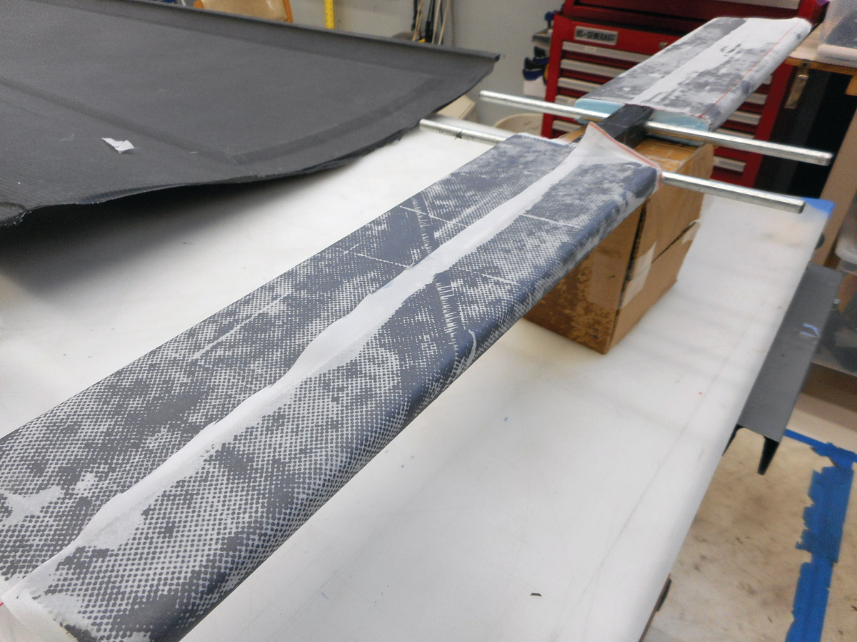
The support wings wrapped in carbon and peel ply. The carbon wings add nothing to the bending strength of the scale wing since the elastic modulus of bias woven carbon is far lower than that of pultruded carbon.
The first step is to determine lambda. While you can arbitrarily set a scale factor of one-fifth, one-quarter, etc., there is nothing that says you need to scale to a whole number. In fact it may be easier to use the relative dimensions of your materials (both full size and scale) to govern the scaling. For example, the SR-1 spar uses a .220 x .092 (0.02024 inch2) rectangular pultrusion. The most convenient pultrusion for scaling was a rod sized .118 inch x .019 inch (0.002242 inch2). Spar cap strength is proportional to spar cap cross-sectional area, so we will use area as the scaling factor. From the table, we know that model area (.002242) = full-size area (.02024) / λ2, giving λ = 3.00 (i.e., coincidentally exactly one-third scale).
The finished spar ready for testing.
A one-third scale model is not a bad size. But remember that we are doing a test to failure, which means we will load the spar to ultimate load. The SR-1 spar is sized for a 700-pound aircraft (which translates to an approximately 600-pound spar load since the weight of the wing does not figure in spar loading) at 8 G with a safety factor of 2, giving a total design load of 600 x 8 x 2 = 9600 pounds. From the table, we know that scale load is inversely proportional to λ2, so 9600 pounds / λ2 = 1063 pounds. This was a bit more weight than I wanted to deal with. However, using a scale factor of λ = 4.25 allowed us to use exactly 1 small pultrusion for every 2 large pultrusions (convenient), with a max load of 532 pounds. This was more to my liking.
Once lambda was determined, it was easy to determine the dimensions of the scale spar box, shear web, and number of spar cap strips since these had already been calculated for the full-scale spar. A spar box beam was hotwired from blue foam and wrapped in bias carbon fiber that represented the shear web. Since the primary goal of this test was to confirm the performance of the pultruded cap strips, we used more shear web than was strictly necessary in order to ensure that the shear web did not fail before the cap strips. Blue foam “wings” were hotwired and attached to each side of the box beam to provide a surface onto which weights could be stacked. Steel rods pass through the spar where the wing attach bolts go on the full-scale spar and support the spar during testing. The spar caps were then epoxied to the top and bottom of the box spar. Finally, the “wings” were wrapped in bias carbon and the scale spar was ready for testing.
Before failure testing, we wanted to calculate deflection. This involved “pinning” one end of the spar and applying a load to the other half, with a pivot point located under the center. A 1-inch Delrin rod was used for the pivot; the Delrin is hard enough not to deform but has just enough give to avoid presenting a sharp point load to the spar surface.
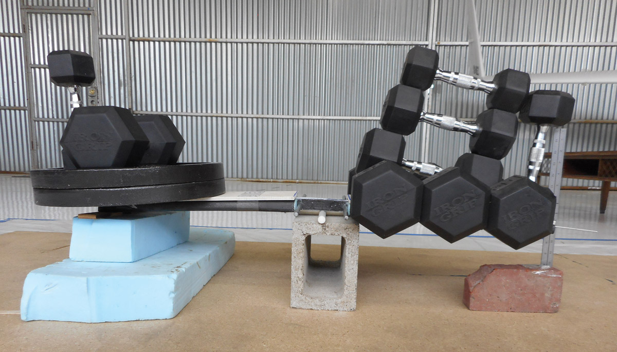
Deflection testing. The white 1-inch Delrin rod under the center point of the spar acts as a pivot. The pinning weights on the left end should only be touching the very end of the spar. Since a certain amount of pinning weight is resting on the spar itself and counteracting the load on the right, the measured deflection is lower than it should theoretically be.

Deflection per unit load is marked on the ruler. A quarter-inch slab of scrap high-density tooling foam (beige color) is taped to the top of the spar to avoid point loads.
Testing the Model
Load was applied 2 G at a time and recorded from a pointer at the wingtip that slid against a ruler. (The reason for not using the steel support rods is that the mathematical model used for load deflection assumes a central pivot point.)
Unfortunately, when we pinned the left end of the spar, we forgot to place a shim under the weights to prevent the pin weights from touching the spar. Therefore, a certain amount of the pin weight is resting on the left side of the spar, counteracting the deflection at the right end and not acting as a true point load. This caused the measured deflection to be somewhat less than what it really should be. Also, due to the relatively small amount of area upon which to stack weights, the load distribution is only an approximation of the actual elliptical distribution one would see on the real wing in flight. The graph illustrates predicted vs. observed deflection. Predicted deflection has been approximated using the conjugate beam method, which is beyond the scope of this article but is discussed in most aircraft structure analysis texts.
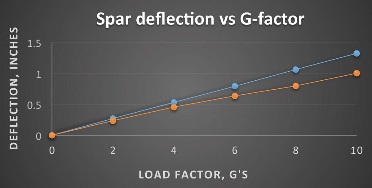
Predicted (blue) vs. observed (red) deflection. Observed deflection is less than actual due to error induced by improper pinning of the spar during testing.
Once deflection testing was finished, it was time to load the spar to failure. This simply required stacking weights on the spar in a fashion that represented the loading on the real wing per the scaling factor. The Delrin rod was removed and the wing allowed to rest on the steel pins.
It is important to measure your scale model before testing to ensure that it is indeed to scale. If the scaling is off, that is OK, but make sure this is reflected in your calculations. For example, the model spar came out somewhat oversize. Recalculating max load based on actual spar dimensions showed max load would be 640 pounds (versus the original 532 pounds). Failing to recalculate would have given the impression that the spar was stronger than it really was.
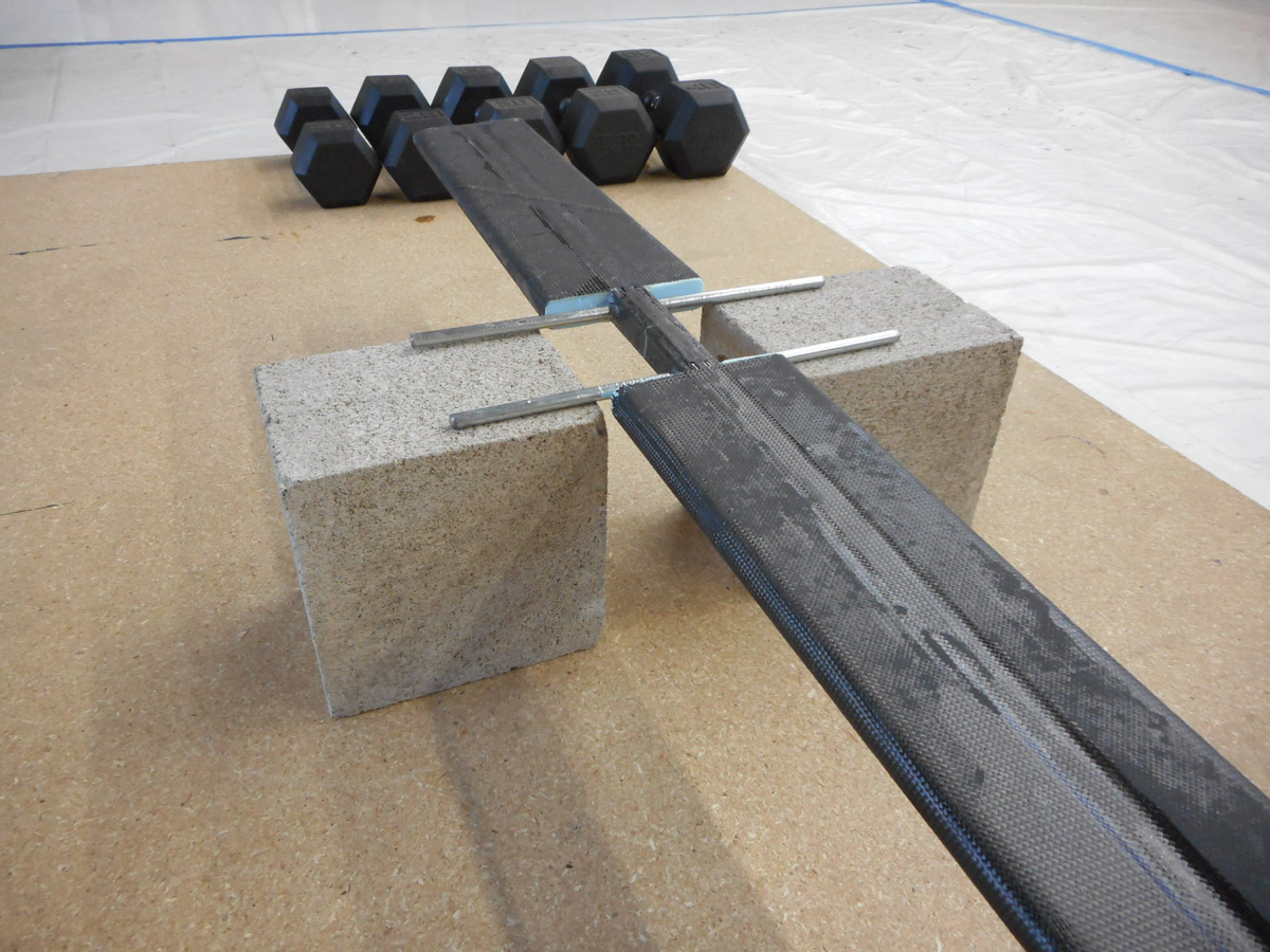
As can be seen in the picture above, a set of stabilizing blocks was located about one-quarter inch under the left “wing.” The left wing was loaded with weights and would deflect downward until it just rested on the blocks. The right wing was then loaded with an equivalent amount of weight and also had a block of foam located about 2 inches beneath it to catch the wing when it failed. This hopefully avoids weights and/or model parts being flung violently around when the spar breaks.
After each load was applied, the left blocks would be lowered another one-quarter inch or so. This pattern was repeated, with approximately 40 pounds of weight being added per time. The spar held 600 pounds, and was subsequently loaded with 620 pounds. It held this weight for 7 seconds before failing (a successful failure test requires holding the load for at least 3 seconds before failure). The ultimate load was thus 620 pounds, or 97% of the predicted value of 640 pounds. The data sheet performance figures for this particular pultrusion thus proved accurate for this model, and our method of construction validated. A video of the scale spar test can be seen at the SR-1 Project Facebook page.
Summary
Like coupons, scale model testing offers an excellent way to hone your skills in preparation for building the real thing, as well as gain some insight into the strength of your design. In next month’s article, we’ll finally get to some fabrication techniques, starting with a simple flat sandwich panel, then work our way up to molded parts.
Acknowledgments: Many thanks to SR-1 Project sponsor Goodwinds Composites for supplying the pultruded carbon rods for both the SR-1 actual and scale wing spar pultrusions. More info on pultruded carbon rods can be found here. More info on designing spars with pultruded carbon can be found here.
![]()
Eric Stewart is designing and building the SR-1, a speed plane for setting records in the FAI c-1a/0 category (takeoff weight less than 661 pounds, including pilot and fuel). You can see more at facebook.com/TheSR1Project, including additional photos and videos of the subjects in this series of articles.


