We’ve had about half a dozen highly technical articles in a row now. It is about time to do some of the easy stuff that you can do without much sweat.
Way back in KITPLANES history [May 1997], I showed you how to make a vertical antenna with a matching coil on the bottom to decouple the coax shield from the antenna elements. The problem with that design is that the antenna had elements capable of receiving/transmitting from one end of the com band to the other, but was limited to some rather closely spaced frequencies by the resonance of the matching coil. I’ve been waiting for 20 years to rectify that little problem, and I think I’ve got a Weir two-fer winner.
The coil was there to take care of the radiation of the bottom element into the coax coming down the other side of that wooden element mounting rod. I’ve been pondering this limitation for a while, and have come to the conclusion (no use rushing things after 20 years) that the only way to take care of the problem is to reroute the coax coming from the antenna elements.

The wooden dowel with copper tape affixed and the coax cable attached to the copper tape.
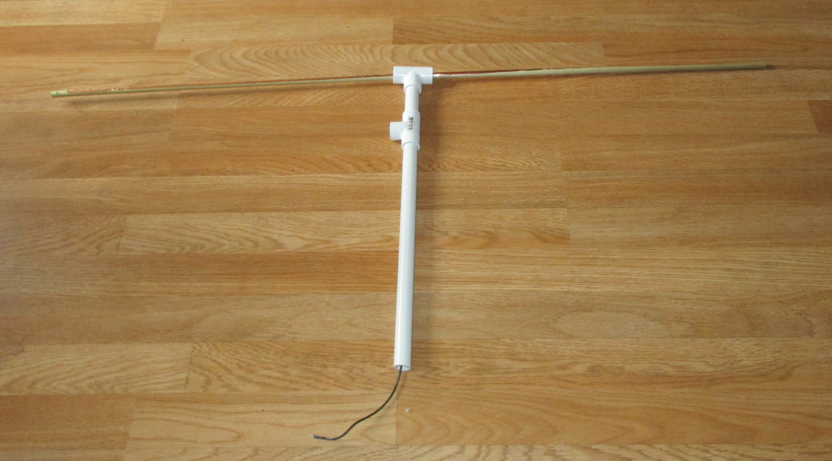
What that means, in essence, is that we are going to complicate the mechanicals and simplify the electricals. Instead of routing the coax out the bottom of the antenna, on the other side of the wooden element mounting rod, I’m going to take it at right angles from the center of the antenna, run it out a reasonable distance, and then put on the connector to the outside world.
The mast mount PVC Tee fitting and two short lengths of -inch PVC pipe.
I could do a little hand waving, give you some plug-in formulas to calculate lengths and such, and that would probably let 90% of you make this little gem without any trouble at all. My particular problem with that is that as a professional teacher, I’ve only given you 10% of the knowledge that lets you understand not only the how, but the why. I got some very good advice from my first boss at PSA (Pacific Southwest Airlines) who told me that (s)he who knows how will always have a job, but the person that knows why will always be their boss. (Harry Somers, thanks for that advice.)
OK then, let’s get started with the l-o-n-g explanation.
We start with the speed of both light and radio waves: 186,411 miles per second or 300,000,000 meters per second, your choice. All my measuring sticks are in “English” (as opposed to metric), so I want to eventually come up with inches for my lengths. I can do it either way, but to do it neatly, I’m going to have to use some conventions and algebra that we learned in high school. Wait, wait, I’m not going to lose you in esoteric math. I promise. Just remember that 102 = 100, 103 = 1000, 104 = 10,000 and so on. Let’s convert those speeds above into inches and into the powers of 10 that we saw above. Remembering that a mile is 5280 feet and that one foot equals 12 inches, we can say that the speed of light in English is 186,411 * 5280 * 12 = 1,181,106,432 inches per second. In our little example above, that can be represented as 11,811*106 inches/second. (The current shorthand for this is 11811E6.)
If we convert the metric measurement, and knowing that a meter is 39.37 inches, we come up with the speed of light as 11811*106 inches per second. Wow, exactly the same number.
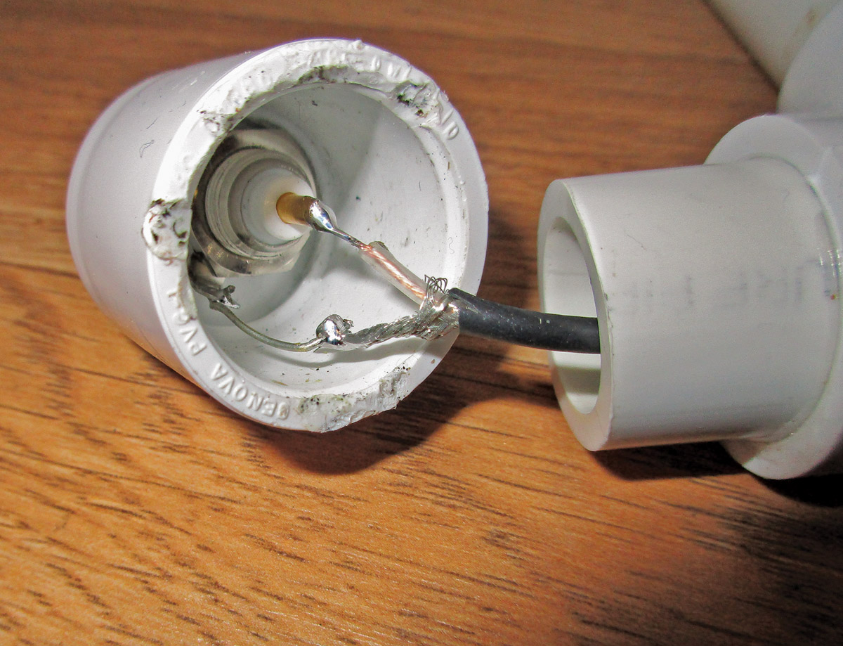
Connecting the coax to the -inch end cap BNC connector.

The BNC connector assembled into the end cap and attached to the coax pipe with a -inch ell fitting.

Using a short length of RG-174 coax to space the wooden antenna element rod to keep the rod from wiggling around in the pipe.
Now we ask ourselves if an electromagnetic wave (“signal”) vibrates, oh, just for example, 127 million times a second (127 million = 127 mega; 127 mega cycles per second is 127 megacycles, or in modern terms, 127 megahertz [generally abbreviated 127 MHz]). Did I pick 127 MHz for some magic reason? Nope, just the frequency in the dead center of the aviation com band. Pick your own “favorite” frequency for the best response from your antenna. And, in our mathspeak from the last paragraph, this is 127*106 or 127E6 MHz.

The completely assembled antenna.
Now we know how fast the radio wave is going and how many times it vibrates per second. We ought to be able to calculate how far that radio wave goes in one “cycle” or one vibration. We call this a “wavelength.” Pretty easy. Speed divided by frequency is how far a radio wave goes in one cycle: 11811E6 / 127E6 = 93 inches. You want to slant the center frequency closer to the low end of the band, say, 123 MHz, your wavelength would be 96 inches (11811E6/123E6).
Now for an easy cheat. Forget the powers of 10 (“E6”). Since the E6 terms cancel out if our frequency is in megahertz (MHz) the shortcut is: wavelength = 11811 / frequency.
Pretty easy, eh? Now I can tell you that 127 MHz antennas are theoretically made from quarter-wavelength elements. Divide wavelength by four and now you know that a quarter wave is 23.25 inches. Theoretically.
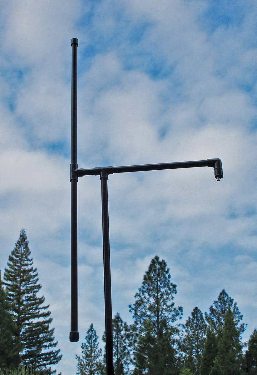
The antenna painted and ready to install. The -inch mounting mast shown here was later replaced with -inch Schedule 40 PVC water pipe for greater strength.
We now depart the science of antenna design for the art. The first thing we have to contend with is what is called “end effect,” which shortens any reasonable diameter (say, larger than #30 wire) antenna element 5% right off the crack of the bat. Multiply 95% by 23.25 inches, which gives us an antenna cut down to 22.1 inches.
Now we have to worry about “fatness” of the antenna elements. If you are making this antenna from #14 Romex wire, you don’t have to worry. If you want fatness, you can get copper tape from hobby craft stores (Ben Franklin, Hobby Lobby, etc.) to go up to half-inch-wide elements. You shorten the element 1% for each 1% of the fatness versus the length. For example, for half-inch tape, you divide half an inch by the foreshortened length of 22.1 inches (0.5 / 22.1 = 2.3%). Shortening the 22.1-inch copper tape still further by 2.3% gives 21.6 inches as the tape length for each ear of the dipole.
What do you gain by fatness? Bandwidth. That is, your antenna is good (a purely subjective parameter) over a wider range of frequencies. Romex may be good for a couple of megahertz either side of center frequency. Half-inch tape is good for about 8-10 Mhz either side of center frequency.
One last “shortening.” We are going to put this antenna into PVC water pipe, and you get a “dielectric foreshortening” as a function of the thickness of the PVC relative to the diameter of the antenna. You can’t calculate this shortening easily, but by measurement we find that it is roughly 1% for the pipe we are using (see below), so the absolute last final length of the copper tape is 1% less than 21.6 inches or a final length of the copper tape of 21.4 inches.
So, here we go with a quick explanation of the mechanical assembly. It turns out that 3/8-inch wooden dowel just exactly fits into 1/2-inch Schedule 40 PVC water pipe. The images with this article pretty well explain how to assemble the PVC pipe into an antenna.
One last “Rev. B” and we are done for the month. I originally intended to use -inch pipe throughout the project. It turns out that this was just a little too flimsy for the mounting mast, so I did a -inch to -inch transition for the 3/4-inch Schedule 40 mounting mast.
Oh, the Weir two-fer? Simply rotate the antenna mast fitting and the connector fitting 90 degrees and you have a horizontal nav antenna if you recalculate the copper tape length for your nav frequency.
This is one of the “easy” construction articles. More to come in future articles…Until then…stay tuned…


