
Late in August 2016, the Pudding River Bearhawk crew (Rion Bourgeois, Philip Groelz and I) pulled a set of short homebrews from the hangar keg, sat back, and contemplated our welded fuselage. It was a satisfying thing to see. Using our accurate construction table and the pre-coped tubing kit from Bearhawk, it had gone together well. Sam Hill’s welding, especially around the multi-tube clusters, was beautiful.
When we started the fuselage, Philip told us, “Let’s enjoy this. Nothing will ever go together faster than the basic fuselage. When that’s done…well, that’s where the work really starts.”
Steel tail ribs were shaped with particleboard form blocks.
Now we were at a place where Rion and I realized the wisdom in that pearl. There’s a heck of a lot more involved in a finished fuselage than just a welded frame. There are tail surfaces, landing gear structure, control mechanisms, and a million tabs that will hold stringers, windows, and sheet metal. We spent an hour of discussion teasing an end out of that yarn ball and decided to continue by starting at the very aft end of the fuselage and working forward. That meant building the tail surfaces and getting them mounted, supported, and functioning.
The tail surfaces of the Bearhawk LSA are conventional in concept but a little different in detail. Usually, in airplanes of this type, the tail surfaces are simple slabs. The Bearhawk uses airfoil-shaped stabilizers with a trim tab in each elevator. The airfoil shape means the stabilizer ribs have to be formed around a form block. The concept is easy—after all, the wing ribs were made the same way. But the wing ribs were aluminum and the tail ribs are steel. In fact, every part of the tail—ribs, spars, and hinges—is made of 4130 steel welded into skeletal structures and covered with fabric.
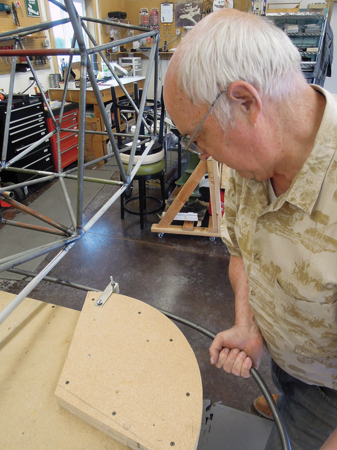
Philip Groelz used a tube bending form to shape the horizontal stabilizer leading edge.
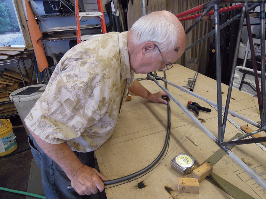
After making the bend, he checked the horizontal stabilizer leading edge for accuracy.
We started with the vertical fin. The tail post—the rear spar of the fin—was already welded into the fuselage, so we used a piece of similar tubing when we laid out the skeleton of the fin on the workbench. Using measurements calculated from the plans, we plotted the position and length of the three ribs and marked their positions on the table—all three are perpendicular to the tail post, so a rafter square made layout easy. For the curved shape of the leading edge profile, we flexed a thin wood batten and tacked it into a curve that started at the correct fuselage station, intersected the front of each rib, and curved back to meet the tail post. There was no math or graphing involved—just a shape that pleased the eye.
Because of the airfoil shape, the cross section of the fin is wider than the 3/4- and 7/8-inch-diameter tubes that make up the leading and trailing edges. I cut blocks out of 2×4 scrap and drilled 3/4- and 7/8-inch holes with the centers equidistant from an edge. When I cut these in half, I had a block with a “cup” in the middle that I could screw to the table and hold the tubing in place. This established the center “plane” of the surface high enough above the table that the ribs would fit.
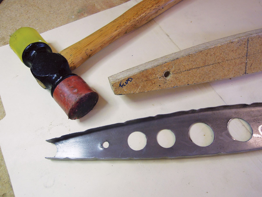
Greenlee punches were used to make lightening holes in the ribs.
Weight that will never fly—removed material from the lightening holes.
Winging It
The Bearhawk drawings do not show the exact shape or length of the individual ribs. Instead, they give a formula for drawing each one. If the overall length (measured between the centerlines of the leading- and trailing-edge tubes and measured directly off the layout on the table) is “x,” then the maximum width of the rib is 0.9x, and that point occurs at a distance of x/3, measured from the front. You’re supposed to use the bottom of the wing rib form block to find a curve that fairs the given points into a smooth arc and draw the top and bottom edges—the ribs are symmetric about the lengthwise centerline.

Airfoil-shaped tail ribs were made from thin steel—not aluminum.
I could never find a spot on the wing rib that actually did this, so we went with the same method as we used on the leading edge—a flexible batten was flexed to fit the fixed points. This line was traced onto paper that was glued to a piece of aluminum strip and cut with a Beverly shear. A few strokes with a file and we had a half-pattern. We flipped it about the centerline to ensure symmetry. Naturally, each rib was a different length and required a different pattern.
The patterns were traced onto a piece of -inch high-density particleboard and cut out with a band saw and a belt sander. The resulting form blocks weren’t real sturdy, but they only had to make one or two parts. We’d made a lot of ribs out of aluminum, but none of us had ever tried to pound steel around a form block. It turned out to be easier than aluminum in some ways—thin steel bends easily with little springback.
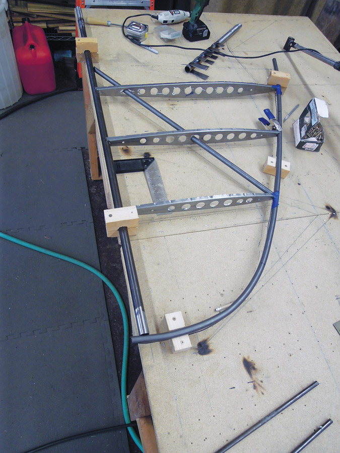
Components for the vertical fin jigged and ready for welding.
No dimensions for the lightening holes were given, just spacings between hole edges. The result is a series of holes, each with a different diameter. That taxed my mathematical abilities, and besides, setting up a fly cutter for each diameter of the hole was tedious. So I used a set of Greenlee punches to make the holes in two sizes: big and little. The result isn’t as geometrically satisfying and probably cost us an ounce or three of weight. I got over that quickly.
The leading edges of the stabilizers and the trailing edges of the elevators are bent steel tubing. I traced full-sized patterns on the workbench and made a particleboard bending form that lag screwed to the corner of the table. This worked fine for the 5/16-inch tubing on the elevator trailing edge but barely stood up to the force needed to bend the -inch tubing used in the stabilizers. Careful application of brute force and constant checking against the patterns gave us reasonably symmetrical control surfaces.
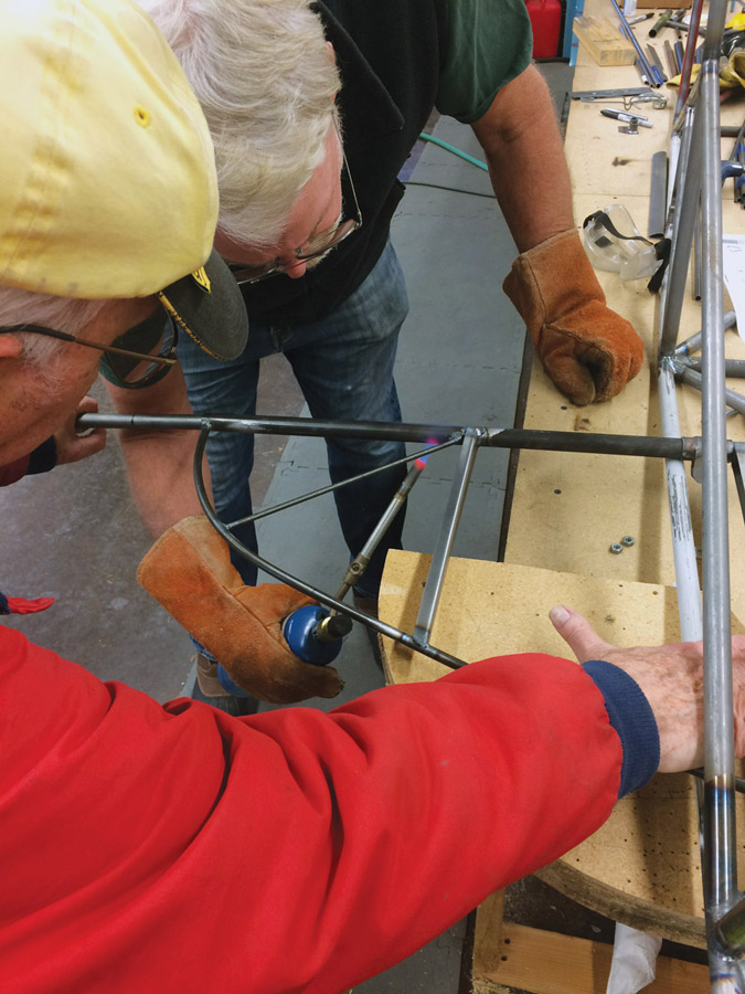
Philip Groelz and Ken Scott straighten the horizontal stabilizer hinge line.
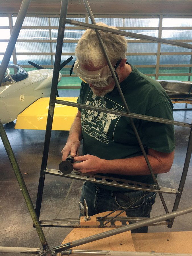
Since Ken wasn’t smart enough to locate the trim tab actuator rod before laying out the lightening holes, a bit of die grinder work was needed.
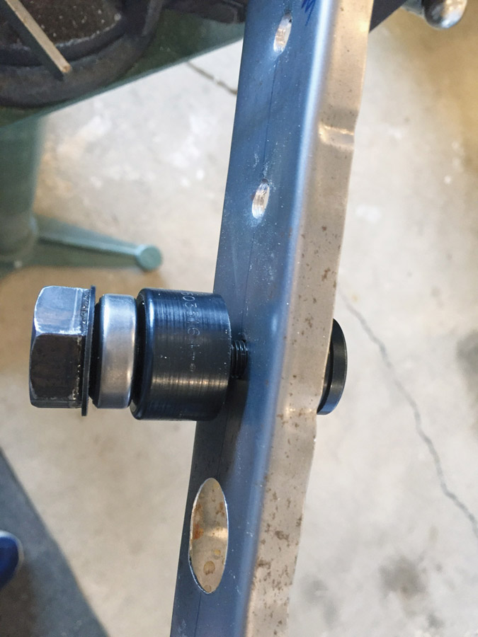
Making all the parts for the empennage took a month or so, working a couple evenings a week, and welding them all together took longer. Eventually we had a set of stabilizers, a vertical fin, a rudder, and a pair of elevators with trim tabs. We fitted these to the fuselage, carefully leveled and squared them up, and drilled holes for the bolts that will attach them. All along, I’d wondered how the elevator/stabilizer attachment would work…most airplanes use a pair of hinges on each elevator and join the elevator bellcranks inside the fuselage. The Bearhawk LSA elevator uses just one hinge. The inboard end of the elevator is supported by a circular bearing bolted into the fuselage. The bearing rides in a special lathed cup welded into the inboard end of the tube that serves as the leading edge of the elevator. Philip considered this a light and elegant solution. I initially thought it unnecessarily complicated, but in the end I realized that other than having to make the special cups on the lathe, it wasn’t harder than any other method.
The horizontal stabilizers are supported by wires, top and bottom, that run between the rear spar and the vertical fin spar and fittings on the bottom of the fuselage. There’s also a rigid strut made from streamlined tubing that runs from the same fuselage fitting to the leading edge—although you’d never know it from the plans. We could see it on photographs of the prototype, but could find no depiction nor any method of constructing or attaching it. There was one cryptic reference to an attachment point on the stab:
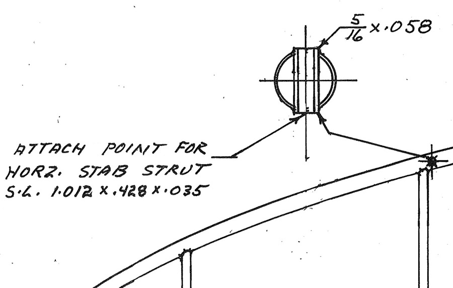
The “Horz. Stab Strut” part was obvious enough…but what did the rest mean? I finally realized “S.L.” means “streamlined,” and the dimensions were the major and minor diameters and wall size of streamlined tubing used to make the strut.
We haven’t needed to call Mark Goldberg at Bearhawk very often, but we called him on this one. As usual, he replied quickly. He found details of the strut and attachment fittings on plans for the similar Bearhawk Patrol, but for some inexplicable reason, they were missing on the plans for the LSA. Mark supplied details from the Patrol plans, and we ordered the tubing from Wicks and welded up the struts. While we had him on the phone, we ordered a bracing wire set, which included streamlined upper wires. Even though Mark gave us a good price, we whimpered when we did it. The streamlined wires were made by Bruntons of Scotland, who has been making them since 1909. The cost of their dies was probably amortized by the time Alcock and Brown nosed over in an Irish bog, but that doesn’t seem to lower the price! But one of the advantages of a partnership is sharing expenses, so we each threw another 2/10 of an AMU into the pot. It’s not like it’s real money.

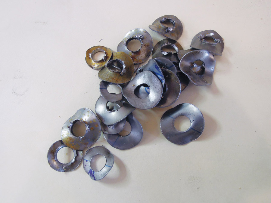
When first installed, the elevator pushrod and trim tab bellcrank collided.

The problem was solved by rearranging some washers.
In a Tight Spot
We spent a lot of time in one cubic foot inside the fuselage, just under the vertical fin. A lot happens there. There is room for the elevator horns, pushrod, trim tab bellcrank, etc. Just…enough…room. Very small variations in building will result in interferences. We had a bad evening trying to figure out how we had managed to make the elevator pushrod and trim tab bellcrank collide with one another. And that, even after we’d used a smaller diameter pushrod than shown in the plans (a detail we spotted in construction photos of the first kit-built Bearhawk LSA). After an hour of discussion on how to rebuild one component or the other, we put the tools down for the night.
I went to bed thinking, as I often have during airplane projects, “How did I mess that up?” The next day, with fresh eyes, we found that rearranging some washers moved the pushrod enough to clear the trim bellcrank and no rebuilding was necessary.
All of us have, on one airplane or another, been really frustrated by the lack of access to important components. Access holes designed for elves, bolts reachable only by triple-jointed internally ratcheting 24-point wrenches…that sort of thing. It would be very easy to fall into this trap in the Bearhawk tail.
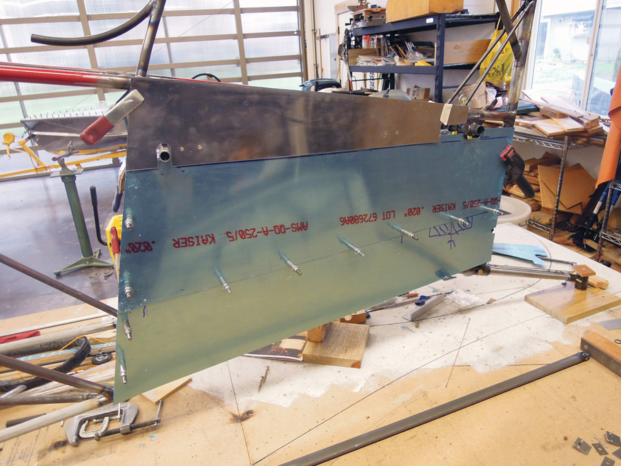
Sheet metal panels provide access to the components in the tail.
The aft fuselage will eventually be covered in fabric, and details of just how to access all the connections and moving parts is left to the builder’s imagination. Philip had similar problems with his Christavia, and solved it by covering the entire fuselage below the horizontal stabilizer with a removable sheet metal panel. We decided to do the same thing on one side of the Bearhawk. I eventually came up with a four-piece sheet metal cover that can be removed in sections. With all of them off, a section roughly 18×26 inches is opened up, and you can get a standard wrench on both sides of every bolt in there. I know it’s heavier than fabric would be, and I can feel Bob Barrows wincing at the thought of “just a few ounces more.” But it’s not as heavy as the frustration of poor access.
As the work went on and on, all concentrated on the very aft end of the fuselage, our operating cry became “out of the tail by Thanksgiving.” My wife and I ended up on a vacation in Santa Fe for Thanksgiving, so the cry became “out of the tail by Christmas!” But Christmas came and went, and we were still finding little things to do before we were truly done in the tail.
Finally we had everything working: All the tail surfaces were rigged, drilled, and braced. All the moving surfaces—the trim tabs, the rudder and elevators—moved the right amount in the right direction and stopped in the correct places. And it was New Year’s Day—on the Julian calendar, anyway.


