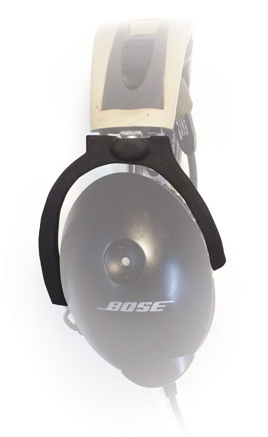
 “Crunch!” Unless you’re eating Doritos, this is not a good sound, but it’s especially bad when it involves a Bose Aviation X headset and is made worse by the knowledge that replacement parts are no longer available. Looking forlornly at a formerly $1,000 headset, my friend (who owned the headset) and I decided that it was worth significant repair efforts to save this otherwise perfectly good headset from the scrap heap.
The first attempt involved using West Systems G/flex plastic repair epoxy to glue the pieces of the earcup bracket back together. This seemed to have a good chance of success as the channel in the bracket provided a nice mold for a thick line of epoxy, gluing not only the flange along the break, but adding additional strength in the bead. Unfortunately, the repair didn’t make it off the workbench as the bracket snapped again in the same place when trying to get it back onto the earcup. This led to a more involved, but more elegant solution: 3D printing a replacement part.
I don’t have a 3D printer and none is necessary to print 3D parts; there are companies to whom you can transmit your file and, like magic, the real thing shows up in the mailbox a week or two later. However, a little planning and a lot of trial and error (and possibly a few printing iterations) may be required to get to a satisfactory finished product. This article will outline the steps I took to create a replacement earcup bracket. If you are using Autodesk’s Inventor, you should be able to follow along and apply the same steps. Other CAD programs might require slightly different operations. Caveat: I’m not a professional. I took an introductory 3D printing course a few years ago and have been slowly teaching myself how to do it ever since. As a result, professional users might spot better or simpler ways to do things, but the following steps worked for me.
The first step in creating a replacement was to reverse-engineer the part to be replaced. In the case of the earcup bracket, this is a bit complex because the part is not symmetrical; one arm is longer than the other, and the arms both curve with tight clearance around the oval earcup. This precluded starting with a standard geometric shape and instead required calculating a custom curve. Fortunately, there is a relatively easy way to do that.
Step 1: Plot the Outline
If you don’t have a piece of graph paper with a 1/10-inch grid pattern, there’s an easy way to get some: print it using a normal paper printer. There are a number of free online applications to do this. I used printfreegraphpaper.com.
With the broken parts laid together on the graph paper, it was easy to trace the outline with a sharp pencil. The origin was selected as a point just below and to the left of the bottom left corner of the part, and X-Y coordinates were marked at each intersection of the pencil line and the graph square’s corners (Figure 1).
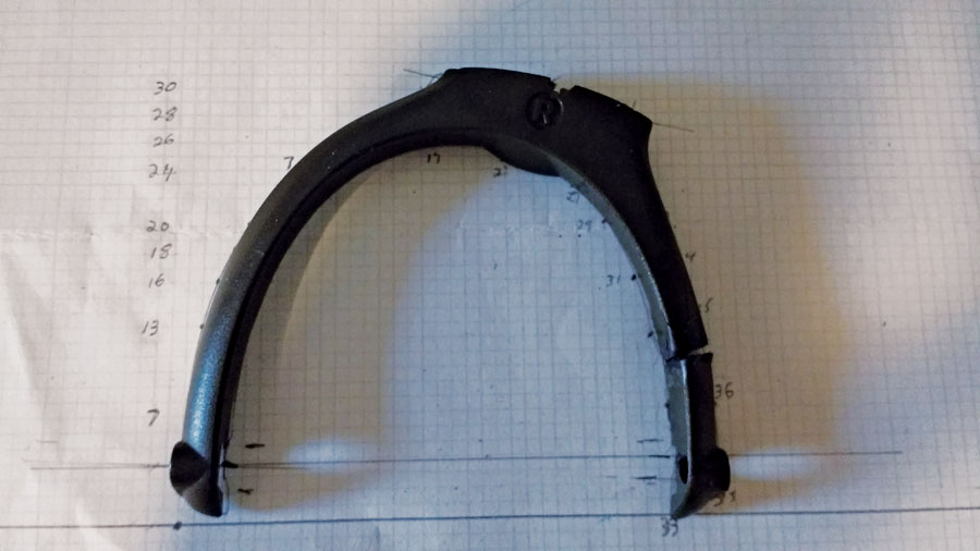
Figure 1: The broken earcup bracket placed on graph paper to plot the X-Y coordinates.
Step 2: Copy the Plotted Coordinates to a Spreadsheet
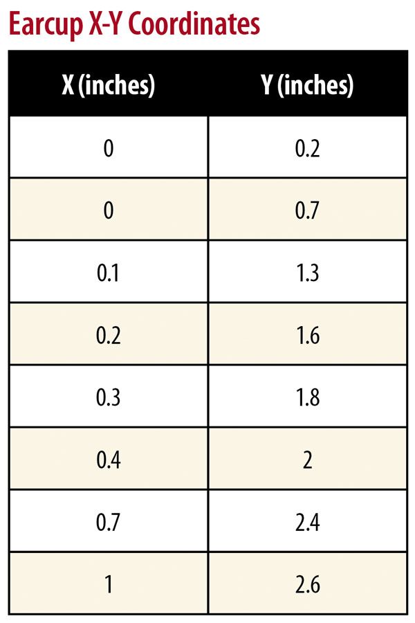
Using the X-Y coordinates from Step 1, a simple two-column spreadsheet was prepared. The plotted grid points were in whole numbers, but the graph paper was marked in 1/10-inch squares, so dividing the plotted numbers by 1/10 provided the X-Y coordinates in decimal inches. These were used to populate the spreadsheet. In total, 41 points were plotted, starting at the lower left corner of the bracket, traveling up the outside edge, then around the lower right corner and back around on the inside edge until getting back to the starting point, making a complete plot describing a closed figure. Figure 2 shows the first few points in the spreadsheet.
Step 3: Import the Spreadsheet into the CAD Program
Select “New/Part” in Inventor, then “Start 2D Sketch,” and choose the X-Y plane. Press the Points button under the Insert menu, and in the pop-up box select the spreadsheet file and press the Options button to select “Lines.” Press “Open” and a 2D drawing of the plotted points should appear, with lines drawn between the points to make an outline of the part (Figure 3).
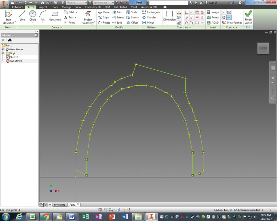
Figure 3: Part outline imported into Inventor.
Step 4: Refine the Outline
In my case, the imported part didn’t look quite right. Straight lines were drawn between the imported points and some of the angles, and point positions looked awkward. Using the mouse, grab any offending point, and drag them into the desired position. The lines will still not be nicely curved, but from a distance they shouldn’t look too bad, and the points where the lines intersect and change direction will be softened with fillets in a later step. When completed, press the Finish Sketch button.
Step 5: Extrude the Part
The basic concept behind 3D design is to start with a 2D shape and then “stretch” or “extrude” it into the third dimension (sounds a bit like The Twilight Zone, doesn’t it?). However, to do this it is necessary to start with a closed 2D figure. In other words, a drawing that doesn’t have any breaks in its outline. Depending on how the plotted lines were imported, this might result in a figure that looks closed, but isn’t. To correct this, under the 3D Model tab, press “Patch” and “OK.” This will create a closed shape. Select the shape and press “Create 2D Sketch” and then “OK” to create a new sketch of the outline of the part. This new sketch will be used for the extrusion. Under the 3D Model tab, press the Extrude button and select the shape. In this case, a micrometer measurement of the arm showed it to be 0.3 inch deep. Enter the depth and press “OK” to create a solid 3D part. Figure 4 shows the extruded, solid part.
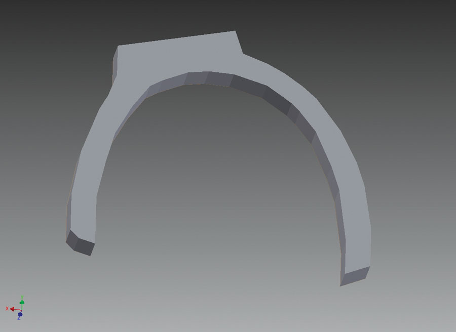
Figure 4: The extruded solid part rendered in Inventor.
Step 6: Hollow Out the Inside
Under the 3D Model tab, press the Shell button and select the face of the part. In this example, a wall thickness of 0.09 inch provides good strength and a channel of a size suitable to press the headset wire into (Figure 5).

Figure 5: Adding a channel to contain the headset wire.
Step 7: Fill In the Solid Sections
Step 6 left a “trench” dug throughout the part, but we want some solid bits to surround the mounting holes. To do this, start a new sketch on the hollowed-out face of the part, and draw lines to create enclosed shapes at the top of the bracket and at the ends of the arms. Extrude these shapes by 0.21 inch, so that they fill in the previously hollowed-out sections (Figure 6).
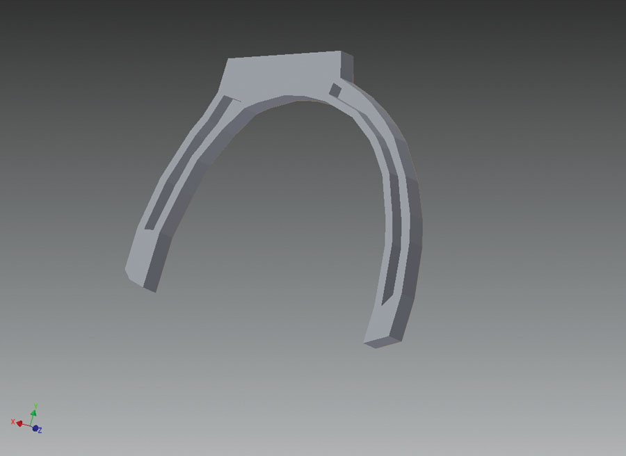
Figure 6: Adding solid areas for the mounting holes.
Step 8: Cut the Angles
At this stage, the top of the bracket provides a flat surface at 90 degrees to the arms, but the original bracket has the top cut at about a 17-degree angle. To accomplish this cut, create a new work plane under the 3D model tab: Plane/Angle to Plane Around Edge, then select the top rear edge of the top of the bracket and specify an angle of -17 degrees (Figure 7). Start a new 2D sketch on the new work plane, and draw a rectangle covering the entire top of the bracket, then do a “Cut” extrusion to cut the desired 17-degree angle on the top of the bracket. Repeat this process to create a new work plane and a new rectangle to cut the inside angle of the top of the bracket, so that it is at 90 degrees to the new top face (Figure 8).

Figure 7: Creating a new work plane.
Figure 8: Cutting the top to a 17-degree angle.
Step 9: Cut the Holes
Select the appropriate faces on the part and press “Create Sketch,” then press the Point button to place hole centers. Finish the sketch and exit to the 3D Model tab and select “Hole,” then choose the appropriate parameters. Repeat this process for each of the holes in the part, including the side mounting holes for the earcup pins, the top hole where the headset sliding bracket joins the earcup bracket, and for the two mounting holes used to mount the metal plate that retains the bracket to the pin of the headset sliding bracket. Each of the holes that accept the earcup mounting pins should be drilled in two sizes and two depths to match the original part: one to accept the shank of the mounting screw and another to recess the head of the screw. Additional holes can be drilled in the top of the bracket if desired to lighten the bracket and reduce cost. The positioning of the mounting holes is quite critical as it has to accept the original parts. To aid in accurate hole locations, you can draw lines on a 2D sketch and use the Dimension button to specify point locations, measuring from the temporary lines. Use a micrometer to measure the depth of the hole at the top of the bracket that accepts the pin from the headset sliding bracket (it is 0.34 inch deep), and select the squared-off hole bottom option. When drilling the holes for the metal plate, specify that they be threaded for 2-56 screws if desired, or alternately set the size appropriate to reuse the self-tapping screws that originally came with the headset. In my case, I specified the 2-56 screws as I was concerned about how effective the self-tapping screws would be in the printed material (they might be fine; I just don’t have any experience with this). See Figure 9.
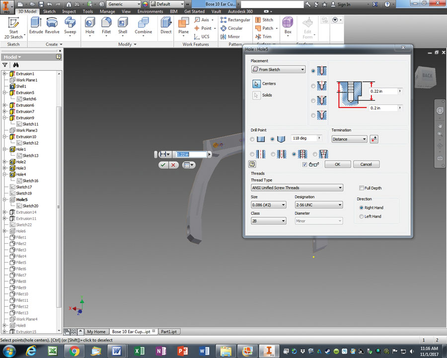
Figure 9: Drilling the threaded holes.
Step 10: Cover Up the Hole Exit
When drilling the hole for the headset sliding bracket to 0.34 inch, because it is at an angle to the outer body of the bracket, the bottom of the hole will exit the side of the bracket. To cover this up, select the bracket surface where the hole appears, and create a 2D sketch of an oval to cover this area, then extrude it outward. This creates a raised mound over the area (Figure 10). Once this is complete, the bottom of the hole will now be partially filled in. Repeat a second hole in exactly the same location as the first and to the same depth to clean out the bottom of the hole where the mound filled it in. Once this is complete, start a new 2D sketch on the top of the oval, and select the Text button to place an “L” or “R.” This can then be extruded with a cut to 0.01 inch to engrave the letter and identify which earcup (Left or Right) the bracket is intended for.
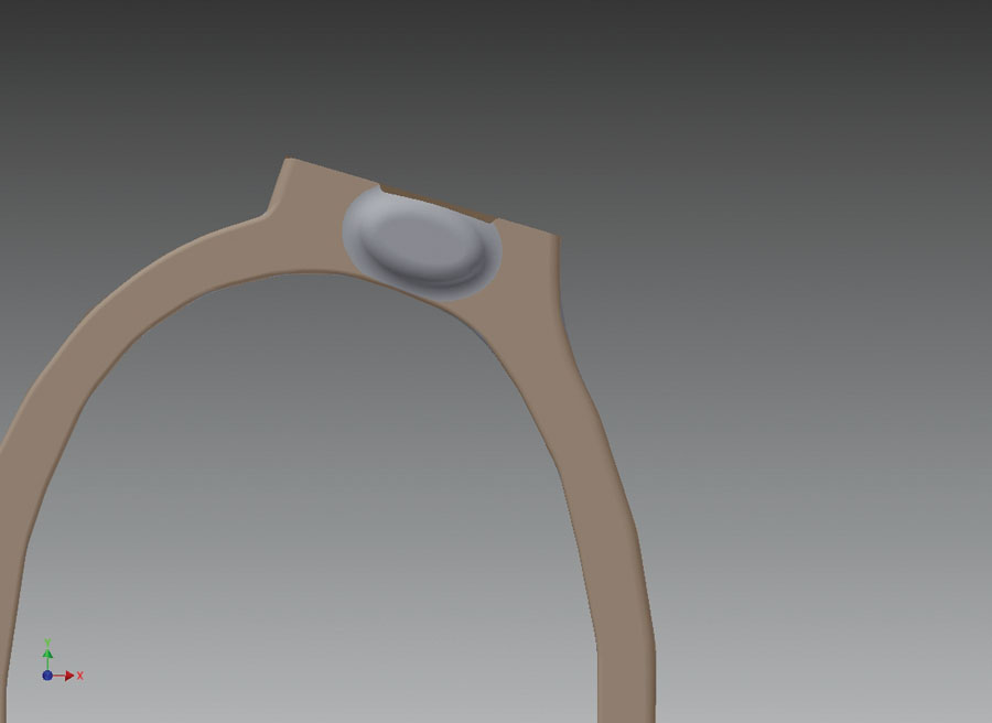
Figure 10: A raised mound covers the exit hole.
Step 11: Cut the Retaining Slot
The headset uses a metal bracket, which has a tab that slides into a slot at the bottom of the pin on the headset sliding bracket. The two 2-56 mounting holes for this bracket were drilled in Step 9, but the tab of the bracket needs clear access to the slot on the pin. To allow for this, select the surface with the 2-56 mounting holes, and start a new 2D sketch to draw a rectangle at the appropriate location. Use a cut extrusion to create the slot. See Figure 11.
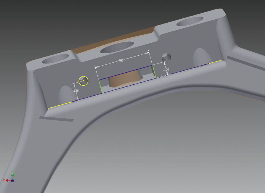
Figure 11: Cutting the retaining slot in the bracket.
Step 12: Add Fillets
The bracket is now functionally complete but has a lot of sharp edges, which are not as attractive and are potential stress risers that could promote a failure. To address this, press the Fillet button on the 3D Model tab, and select any sharp edges for which rounding is desired, specifying the appropriate radius for each one.
The bracket is now complete! To create a bracket for the other side, it’s not necessary to repeat all the above steps. You can simply press the Mirror button on the 3D Model tab, select the plane that you want to mirror around, and the application will automatically create a mirror image of the part for the other ear. You can then change the embossed letter from “L” to “R” or otherwise, as appropriate.
There are a variety of third-party 3D printing services available online. I typically use shapeways.com. To upload a file to them, first save the original, then select “File/Save As/Save a Copy As” and select “STL” as the file type. It’s very important to press the Options button on the pop-up box to specify that the part is measured in inches.
If you would like to simply 3D print the bracket created for this article, you can do so by going to the Shapeways site and search for “Bose.” As of this writing, the printing cost for the bracket is $8.84 and shipping is $5.00. These are the charges from Shapeways; I am not taking any markup for the part.


