
Because of their extremely low operating current, digital multimeters do not do a good job of measuring resistance in the field circuit of an alternator, so it is best to use an old-style analog meter for this.
If your eyes start to glaze over when faced with an electrical problem, relief is in sight. The volt-ohm meter (VOM) is simple to use and can provide quick answers to most electrical troubleshooting problems with just a little bit of knowledge and practice. Everyone who works on airplanes should have one of these tools. Here we will talk about how to use it.
What are Volts and Ohms?
An analogy that is often helpful when it comes to understanding volts and ohms is the water hose analogy. If you think of a wire as a water hose, there is pressure (volts), friction in the hose or restrictions such as a kink (resistance measured in ohms), and flow based on the pressure and the size of the hose (current measured in amps). If we have an electrical problem, it might be that the hose (wire) is too small, the pressure (volts) is too low, or that there is some sort of an impediment to the flow (resistance). In electrical terms think of an impediment to flow as a poor connection or a broken wire, which would impede the flow or electrons through the circuit.
Ohm’s Law gives us the relationship between voltage, resistance, and current in a circuit, but I am going to try and steer clear of theory as much as possible here, since this is really more of a how-to article. Here it is for those who insist:
I (amps) = V (volts) / R (ohms).
Anyway, a volt is a measure of electromotive force in electrical terms. This is analogous to pressure. Resistance, measured in ohms, is that which impedes the flow of electrons in a circuit. Current, measured in amperes (amps for short), is the volume of the flow of electrons through a circuit.
We care about volts because our electrical components and avionics need a certain voltage to work. If the voltage is too low, things just stop functioning. If the voltage is too high, things can get damaged, and the things that can get damaged tend to be expensive.
We care about resistance or ohms because too much of it causes voltage to drop. In extreme cases high resistance leads to a lack of continuity, a fancy way of saying current can’t travel through the circuit. Small amounts of resistance are inevitable in any circuit, but too much causes us trouble, such as engines that won’t turn over or instruments that won’t read correctly.
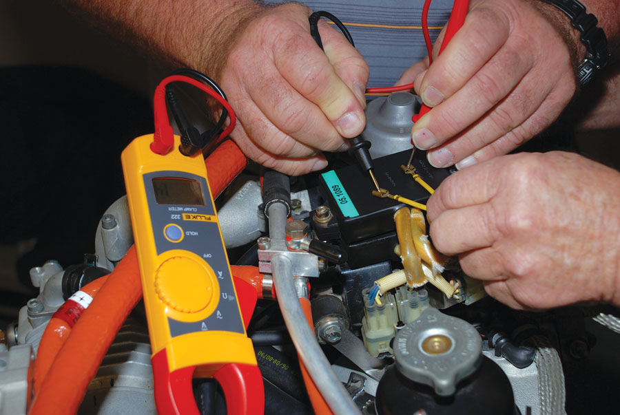
The Rotax charging system is a special case and calls for its own diagnostic and repair procedures. There are some simple resistance checks that you can perform to check the alternator. First disconnect the alternator at the plug. Check resistance between the yellow wires and between each yellow wire and ground. Yellow to yellow should measure 0.1 to 0.8 ohms. Yellow to ground should be open (infinite resistance). Next check the resistance between the red wire and ground. This should be in the range of 3.2 to 4.5 ohms.
Measuring Volts with a VOM
Unless you have a fancy VOM with automatic ranging, you will need to select the voltage range that is appropriate for what you plan to measure. A range with an upper limit of 20 volts would be ideal for most experimental airplane electrical systems that usually do not see voltages of more than 15 except at the spark plugs. Besides the range, it is important to pick direct current as opposed to alternating current. Direct current is what we get out of a battery. Its polarity does not fluctuate. Alternating current, what we get out of the wall socket, reverses polarity 60 times per second.
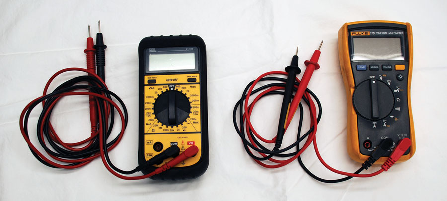
On the left is an inexpensive VOM available for less that $40. It will suffice for most voltage and resistance measuring tasks on your airplane. With this meter the volt and ohm ranges must be selected manually. On the right is a Fluke VOM with automatic ranging. It is a much more accurate meter, but it costs about $100 more.
The thing to remember is that our normal airplane circuits use direct current. Even our alternators, which admittedly produce alternating current, rectify that current into direct current before it ever leaves the alternator. Lastly, polarity matters with DC circuits. The positive lead needs to go to positive and the negative lead needs to go to ground.
A good place to start is to check the battery. Touch the positive lead to the positive battery post and negative to negative. If there is any corrosion or paint present, you will need to remove it to get a good connection. Your battery should read around 12.8 volts if it is fully charged. If it actually reads 12.0 volts, you need to put it on the charger. If you check the voltage output of the charger, you will see something like 13.5 volts. This is because the voltage at the charger must be higher than the battery voltage to get current to flow to the battery. It is a basic law of electricity that current will flow from where there is higher voltage to where there is lower voltage, just as heat will always flow from where it is hotter to where it is cooler.
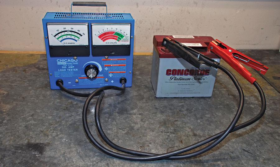
The voltmeter portion of this battery condition tester shows a fully charged voltage reading of 12.8 volts. This reading is being taken with no load on the battery.
If things look good at the battery, but you are having a hard time starting your plane, your next stop is to check the voltage at the output side of the master relay. This may be slightly less than the voltage at the battery, especially if your battery is mounted some distance from the master relay, but slightly less means 0.1 or 0.2 volts less. If it is more than that, look for a poor connection somewhere or possibly a bad master relay. Remember, you can measure the input voltage at the master relay with the master switch off, but to measure the output voltage the master switch must be on. In all cases you must have a good ground connection for your meter to get an accurate voltage reading. If you can get a ground lead for your meter that has an alligator clip, it makes things much easier.
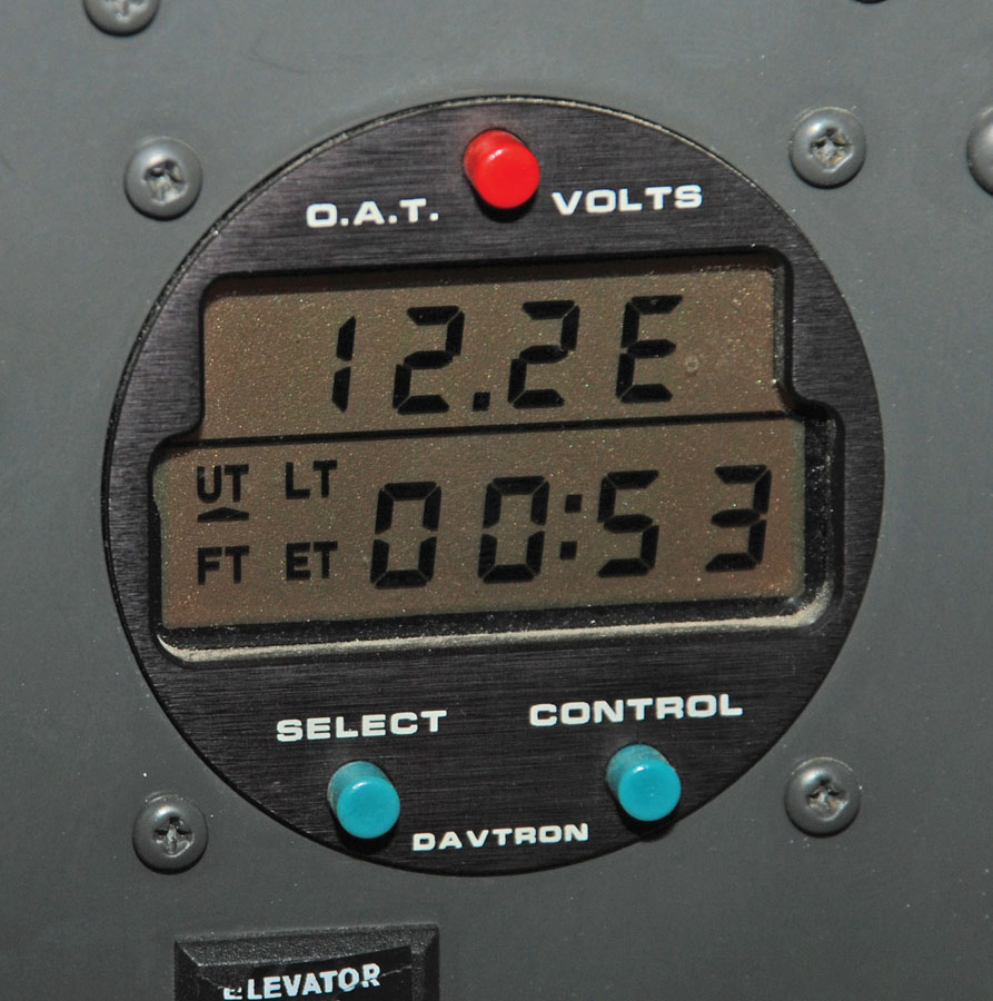
You may have a voltmeter in your plane such as this one that is part of a Davtron clock/timer. Most EFIS systems also include voltmeters. This voltage reading comes from the main bus after the master switch has been turned on. This reading of 12.2 volts shows a battery that needs charging before flight or possibly some unwanted resistance in the connection between the battery and the main bus.
If the voltage at the master relay looks good, we can move on to the starter relay. You can measure voltage at the input side of the starter relay by merely turning on the master switch. However, to measure the output voltage of the starter relay, you should first disconnect the lead going from the starter relay to the starter. Otherwise, the engine will turn over when you turn the ignition switch to start. The voltage drop across any relay should not be more than 0.1 volts. If it is more than that, then we need to find out why.
The most common cause of voltage drop through an electrical system is a loose or corroded connection somewhere. If the battery is well charged, but the engine won’t turn over as expected, look at the condition of each connection first. Remove connections one at a time, and clean them down to bare metal. Then reinstall the connection to the proper tightness. Many times just removing and reinstalling D-sub pins, FASTON, or Molex connectors will remove oxidation and reestablish good contact. While you are checking things, don’t forget the ground strap to the engine or ground wire attachment. Poor continuity there is every bit as important as it is with the positive connections.
Another place you might want to check voltage, especially if you are having possible alternator problems, is at the power line from the alternator. You can also measure the output from the voltage regulator if it is separate from the alternator. The alternator should be sending somewhere between 13.8 and 14.2 volts to the battery in most cases. If you are using a lithium battery, it might be helpful to increase that a bit based on the battery manufacturer’s recommendation.
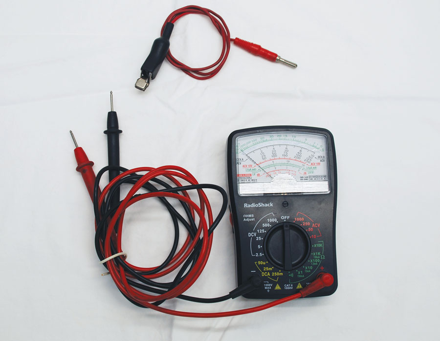
An analog meter such as this one is available for a very reasonable price and can do some jobs even better than a digital meter. Shown with it is a lead with an alligator clip on one end. This can be very handy when probing for problems.
Measuring Resistance
Resistance is measured in ohms represented by the Greek letter Ω (omega). In simple terms, resistance is that which impedes the flow of electricity through a circuit. If resistance is infinite, we call it an open circuit. This is when a wire is broken or disconnected, or maybe a fuse is blown or a switch is turned off. Impedance is also measured in ohms. Speakers and antenna wires are rated in ohms impedance, but impedance cannot be measured with most meters because it is a combination of resistance and reactance.
Before we get too far ahead of ourselves, let’s look at how resistance is measured. The VOM must be set up in the proper range. If you are just testing for an open circuit or a short, then a high range works fine. If you are testing for small amounts of resistance, then a low range will work much better. Unlike with DC voltage, there is no polarity to worry about when measuring ohms. However, there is another thing we do need to worry about when measuring ohms, and that is accidentally using the VOM to complete a circuit. Because of this, it is generally a good idea to have the power turned off or disconnected when measuring resistance. It is too easy to make a mistake and damage your meter.
The most basic test that we can perform with a VOM measuring resistance is the continuity test. This tells us if we have an open circuit or a complete circuit between any two points; in other words, do we have continuity? If a wire is broken, a circuit breaker is tripped, or a connector has come loose, we will get an open circuit. This will be shown by no reading on our meter. If we have good continuity, we will get a low ohm reading, depending on the sensitivity range we have selected. Some meters will simply beep if there is good continuity. This makes it very easy to check circuits without being able to see the meter.

Here a starter relay is being tested on the bench for internal resistance. A battery charger is used to activate the relay. With a resistance of 0.1 ohms, this relay is fit for service. When measuring small amounts of resistance, it is important to be sure you have a very good connection at the probes.
Another good use for a VOM set in resistance mode is to trace a wire from one point to another. Since airplanes are usually wired with all white wires, it can be difficult to figure out which wire is which in a bundle of wires. Simply clip one lead to the end you know and use the probe on the other lead to test each wire until you find a good continuity. This can get tricky if two wires in the same bundle connect to the same device. For example, if two wires go to a flap motor, they may both show continuity because the test current is flowing through the motor. However, the wire being sought should have much lower resistance than the other wire.
If we go back to our volts example, we can use the resistance side of our VOM to track down the same problem. We could first measure the resistance between the battery post and the hot side of the master relay. The resistance even on the lowest range should be very low, say 0.2 ohms or less. We are hoping for a total resistance from the battery to the starter of about 0.5 ohms or less. Much more than that means something needs to get fixed.
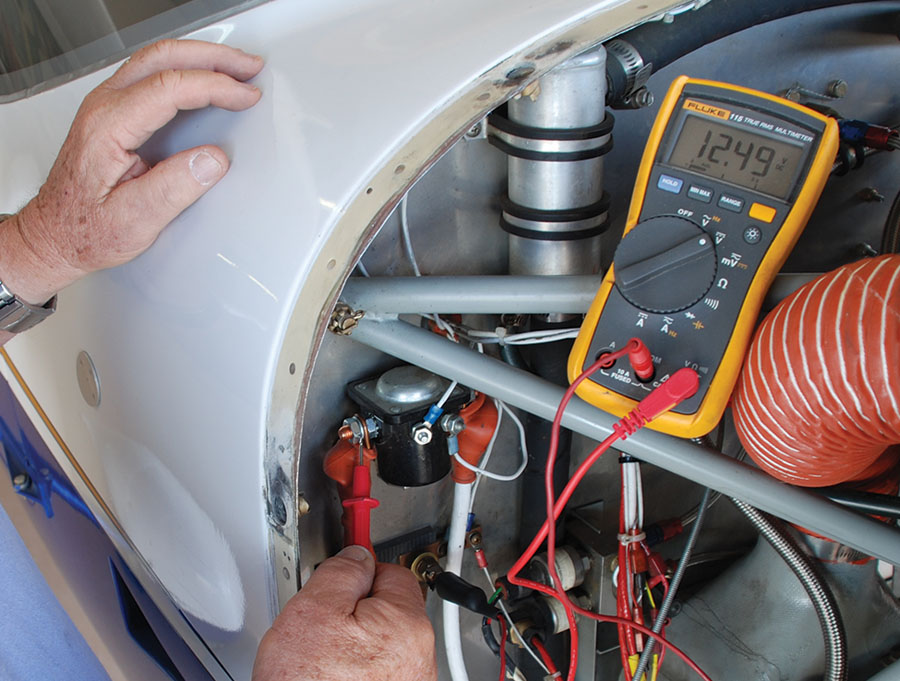
The VOM shows 12.49 volts at the starter relay. That is a little low but is likely due to the rear-mounted battery and the long cable forward.
A few notes on measuring resistance. It is important to test your meter before starting to work by touching the two leads together to make sure you have zero ohms resistance. On the old analog meters there was a way to zero out the meter when performing this test. Digital meters should not need to be adjusted to zero ohms. In all cases solid contact is needed to get a good reading, so watch out for poor connections between the leads and the objects being tested. Also, if you are measuring resistance between points that are several feet or more from each other, for example the battery cable when the battery is mounted in the rear of the airplane, test the resistance in your extended lead first to see how much resistance is there. This should be subtracted from your other readings.
One thing to keep in mind as you try to measure resistance is that it can be hard to know exactly what you are measuring when wires are connected to devices. Sometimes current can flow through these devices and give you readings that don’t make any sense. When in doubt, disconnect wires from the devices they power and then measure resistance in the wire.
For those who are new to the use of a VOM, the best thing to do is to take some measurements of various things to get some practice and confidence with the meter. Get some help from a more experienced builder if you are still confused. Once you get familiar with the VOM, you will find it to be a handy tool for tracking down electrical problems.


Some comments by an electrical engineer/ pilot;
– per Concorde, a battery with an open circuit voltage [ no load on the battery], should be 12.75 volts, or higher.
If it is lower, recharge the battery.
– a normal charge voltage is 14.0 to 14.2 volts, but is temperature dependent.
see https://www.concordebattery.com/knowledge-base.html?media=tb
– resistance in a circuit with cause a voltage drop across the part that has resistance between it’s terminals.
The only way to determine the internal resistance of a part is to put a current through it.
You can turn on the master and add a load of 10 about amps.[ lights, pitot heat ].
So, if there is a resistance of 0.1 ohms, then a 10 amp load will result in 1.0 volts drop across the terminals…
BTW, most analog meters have a 4-5% measurement accuracy vs a digital meter having 0.5 -1% .
So, measuring a battery at 13 volts, the analog meter can have an error of 0.65 volts !! vs the digital meter error of 0.06 to 0.13 volts. [ see the Concorde note above ].
When troubleshooting low voltage at the loads, make sure to check the battery ground cable connection to the airframe…a clean connection and no washers between the cable terminal the airframe. [ it adds resistance ].