I met my first wing spar when I was 13 years old. I had joined a group of boys meeting at an FBO to restore a couple of J-3 Cubs—the FBO owner got free labor, and we got an education that eventually included flight lessons, a win-win for all. That first night, I was handed a brush and a can of spar varnish and told to coat that long slab of wood. It was the heart of the wing of the J-3 we’d eventually be flying. It looked just like a long plank to me, but I was told it came from a special type of tree, a Sitka Spruce, known for long, straight, and uniform grain. It looked pretty to me, but it took many more years of building airplanes and studying to be an aeronautical engineer to really understand just how special the main spar of a wing really is. It is more than just a place to attach the ribs—it is the core of the structure that supports the act of flight.
We’re going to begin this three-part series on spars with a discussion of the loads carried by spars, how they are constructed, and how various materials can be used to construct the different types of spars. In later installments, we will cover the construction of the spars for a typical all-metal wing—in this case, the main spars for a Xenos motorglider, a good example of a typical metal spar with many different components working together to form a cohesive unit. We’ll show how the spar goes together and how the various components work together to take the flight loads on the long, slender glider wings. These articles should give you the understanding necessary to decide if you want to build your own spars or buy them preassembled, a common option for kit aircraft today.
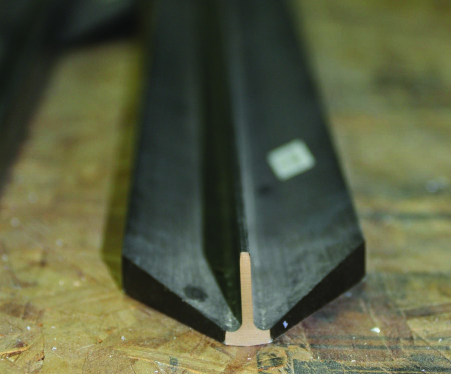
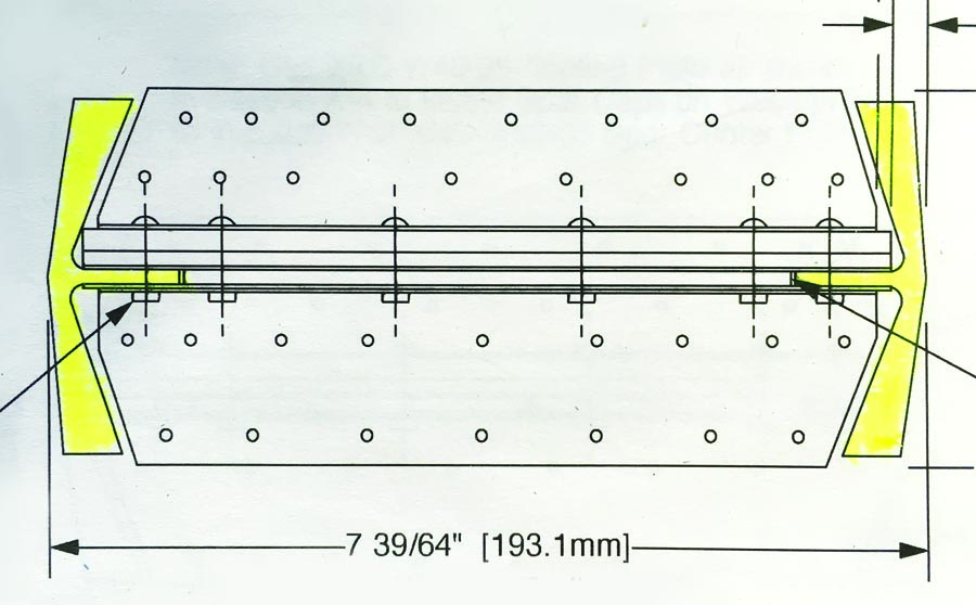
One of the spar caps for the Xenos motorglider. Note the “T” shape—the vertical portion mates with the spar web, and the strength lies within the top of the “T.”
Bending Axes
Most wings you’ll run across sport a single main spar as well as a smaller rear spar. The two act together, in concert with the ribs and struts, to create a rigid, strong, yet light space frame that supports the aircraft in flight. The main spar resists bending primarily in the direction of the lift vector—that is, up and down. When combined with the rest of the wing structure, it resists forces in the fore and aft direction, but the spar by itself is actually a bit of a limp noodle in that axis. A typical spar is taller than it is wide, and the reason is because of that primary bending axis—the wing primarily wants to bend in the up-and-down direction and, therefore, it needs to be thicker in that dimension.
If you take a piece of 1×1-inch lumber from the local hardware store, you’ll find that you can bend it equally far in just about any direction (be careful—those sticks can snap suddenly!). But if you take a similar length of 2×4-inch lumber, you’ll find that if you try and bend it across the 2-inch face, it will give quite a bit—but load it across the 4-inch dimension, and it will be pretty stiff and rigid. If you’ve never framed a house, take a look at one that is under construction, and you’ll see that all of the floor joists are oriented such that the loading is on the long dimension of the lumber. This is simply to put most of the material to work for you, resisting the bending loads and keeping the structure rigid.
If you were to measure the actual strain in a spar (or a length of 2×4) under bending loads, you’d find that the wood strands on the top of the spar are being compressed—that is, pushed together in the long axis. At the same time, the strands on the bottom of the spar are being stretched—they are under tension. This is easily seen in the accompanying drawing. The interesting thing to note is that the closer you get to the center (between top and bottom), the smaller the loads become—the compression loads on top and the tension loads on the bottom decrease as you approach the center, or neutral axis, of the spar.
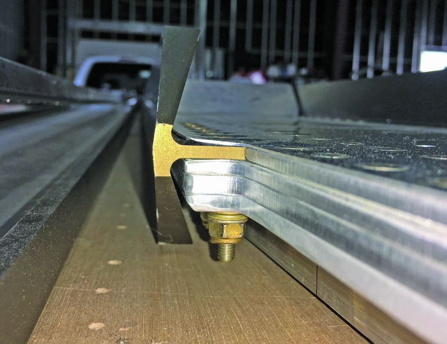
This picture of the root end of the Xenos spar shows how the leg of the spar cap “T” fits into the layers of the spar web. At the root end, bolts are used to anchor the cap; as you move outboard, it is all rivets.
That hardly seems fair, does it? The fibers on the bottom are working hard to hold together under tension, and the ones on the top are working hard not to be crushed, but those in the middle get a free ride! It is this realization that brings us to the first modification to the “slab spar” design—one that is simply a solid rectangle of wood. If the middle fibers aren’t taking their share of the load, what are they doing there? They are just adding weight, aren’t they? Isn’t there a way to reduce that portion of the spar and make the structure lighter?
Well, of course there is—and thus is born the “I-beam.” Since the majority of loads are being taken by the top and bottom edges, and the middle is just loafing along, keeping the edges apart, why not make the middle portion skinnier? That is exactly what you see when looking at a steel structure, like a building or a bridge: The main structural members are shaped like the letter “I” in cross section. The edges (the caps) are broad and load bearing, while the middle (or web) is there mostly to keep the caps from collapsing toward each other.

A spar built in the form of an I-beam puts the thick, heavy material of the caps under load (compression on top, tension on the bottom), and minimizes material where the load is small (in the web).

Flying the I-Beam
Since we got started with wood, there’s no reason why we can’t continue that train of thought for a while. Wooden I-beams are commonly used for floor and ceiling joists in wooden structures, with the caps often made of 2×4 material laid on its side, and the webs made from relatively thin plywood. Aircraft spars can and have been made this same way—with the strength of the wing being in the caps, and the web simply there to hold them apart.
There is no reason why we can’t take this same concept forward to metal construction. A typical aluminum spar these days will be built with separate spar caps—usually with large cross sections—and much thinner webs, often laminated from multiple sheets of aluminum. The caps are frequently bars of aluminum or extrusions in specific shapes to spread the bending loads at the top and bottom of the spar. Some older all-metal spars intended for homebuilt construction were built up from layers of thick sheet metal that was readily available (like 1/8-inch) so that special extrusions or heavy riveting was not required. If you have one of these laminated spars, it is going to be plenty strong, but possibly not as light and weight efficient as a newer design with specific caps.
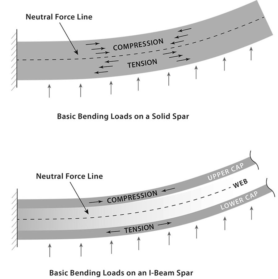
A solid spar of uniform cross-section (typically made of wood) has varying load from top to bottom. The bottom wood fibers are under tension, and the top are in compression.
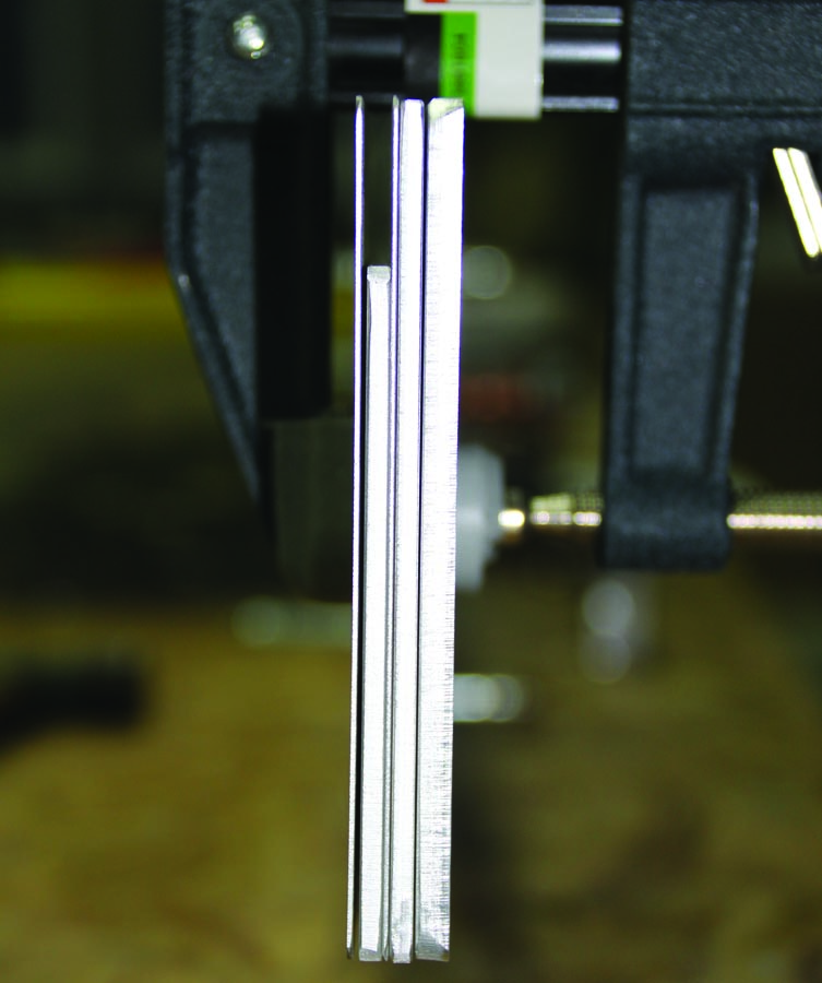
In many cases of optimized design, spars are not uniform from root to tip. That is because the closer you get to the tip of the wing, the lighter the load carried by that portion of the wing and, therefore, the less strength you need. The Xenos wing we are using as an example in this and future articles is like this. With a very long wing, there would be a significant weight penalty if you kept the same cross section from root to tip, so as you move outboard, both the web and the caps become less substantial. The caps are tapered extrusions, and the web uses fewer and fewer layers as you progress to the tip. In fact, the web at the root is made up of six layers of material up to 3/16-inch thick, and this tapers down to a single layer of .032-inch sheet metal by the time you get to mid span.
A Word on Composites
Composite wings obey the same laws of physics and mechanics as metal structures do, and the same is true of their spars—but they can look a bit different. You will still see composite spars that look like I-beams embedded in wings, but because the designer has so much flexibility in layering the cloth that goes into the wings, sometimes the spar structure is blended in with the wing skin and is not quite so obvious. Integrated structural design puts the strength exactly where the designer needs it, and you will find structures with no obvious spar at all—but you can bet that it is designed in with the necessary layering to produce the desired strength in the correct direction.
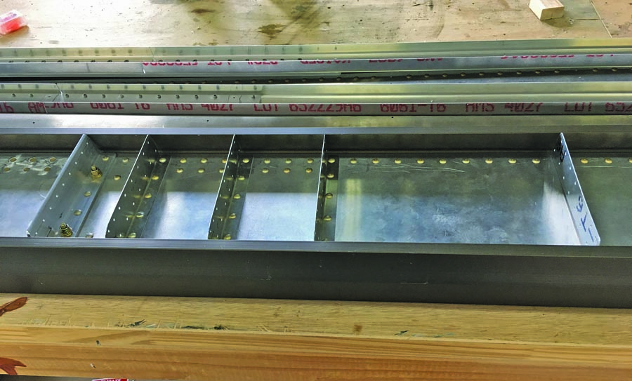
When spar webs get particularly thick near the root, the flanges of the ribs need to be riveted to the assembly when the spar is built. The clips on this spar will hold the inboard ribs.
The Web
Going back to aluminum: As mentioned earlier, the material of the spar web is there primarily to hold the caps apart and keep the spar from collapsing. From a purely structural statement, that is accurate, but in the real world, it does a great deal more. Probably the most obvious thing is that the ribs can be mounted to the web. In an older frame-and-fabric aircraft, it is common to have one-piece ribs that slide down the spar (some metal airplanes use this design as well) to their stations, where they are fastened. More frequently these days, the ribs consist of multiple pieces: a piece ahead of the spar, and another behind. These two pieces are riveted to the spar web where they meet.
The web of a typical metal spar is built up of multiple layers, the number of which goes down as you get toward the tip, where less load is carried. For the Xenos, the leg of the spar cap fits into the slot at the top.
The web can also be used to mount things like control-cable pulleys or bellcranks. In this case, the web is often reinforced with a doubler plate to make it locally stiffer to take the sideways loads imposed by the controls. The web might also support fuel tank mounting structure, as well as wiring conduits or clamps.
Speaking of wiring, it is not uncommon for builders to ask if they can run wiring through the wing from front to back by penetrating the spar. This is a good question to pose to the designer, but you should understand by now that since the center of the web generally carries no compression or tension loads, holes through the web near the middle are usually not a problem. Again, check with your designer to make sure, but if you can’t understand why it is OK to have holes in the spar, understanding the load path should give you some comfort. This does not, of course, give you carte blanche to drill as many holes as you want anywhere in your spar—but it does explain how and where penetrating it is OK.
The Caps
Spar caps, as mentioned, can be specially shaped and tapered extrusions or simple rectangular blocks of aluminum, depending on how the designer wants to optimize the weight of the spar and how available they want the parts to be. For plansbuilt aircraft, builders generally want to be able to buy standard raw stock. For kits, it is OK to use custom materials, so long as builders understand that the factory will probably be the only source of replacement parts. Spar caps are generally continuous from root to tip, so messing one up during construction can mean expensive shipping for the long replacement. On the Xenos, the caps are close to 25 feet long each. Shipping one across the country is not cheap, since it needs to be packaged well to prevent it from being bent.
It is important to treat spar caps carefully, since these are the structural elements that truly keep you aloft. Elements in tension are being stretched, and are not susceptible to buckling, but those in compression (generally the top web in level flight) are being compressed. If you have ever put your weight on an empty soda can and then tapped the sides to make it collapse in an instant, you have experienced failure due to compression buckling. Think about that the next time you see a dent in your spar cap. Maybe that expensive shipping charge isn’t so bad after all…huh?
Drilling holes in caps other than the ones that the designer calls for is a no-no. Treat them with care, and make all holes exactly per plans and specifications. Tight-fit holes should be drilled and reamed to the correct dimension. Enlarged or oblong holes are reasons for rejection. Nicks and divots likewise—keep those caps pristine, and you’ll be able to have confidence at 3 (or more) G once you are flying.
Fastening it Together
Most aluminum spars are riveted together, with bolts often added at thick points because setting rivets greater than 5/32 inch in diameter is difficult, and at some points, the strength of a steel bolt is required. You will most often see bolts used near the root, where the loads are highest. Wooden spars will frequently sport steel splice plates and bolts near their roots for the same reasons: the overall spar loading is great at the root, and the material must be reinforced to assure adequate margin. In any case, it is important to use the fasteners called out by the designer and accept no substitutions without explicit permission.
Of course, wings eventually have to be attached to a fuselage in order for them to work with the tail and motor to make a flying airplane. The spars are the major attach points since they are what is carrying the load, and it surprises many new builders to find out how few bolts it takes to hold their wings on. Or, in the case of some planes, how many! An old Cub will generally have just a single bolt holding the root end of the main spar for each wing, and one for the rear spar as well. Then the wing struts are bolted on mid-span at their top ends, and to the lower fuselage longeron at the inboard, lower end. This triangular truss is quite strong when loaded positively (not so much when pulling negative G), and the bolts are fairly large.
A typical low-wing airplane will feature a stub spar as part of the fuselage structure—a section built like the rest of the main spar, as thick and beefy as the root section, but securely part of the fuselage structure. The wing spars’ roots will then overlap the stub center section spar and bolt to it with sufficient large bolts to fix the wing rigidly in place. This sets the designer’s dihedral angle and creates a cantilever design that requires no struts. Many metal aircraft do not have as beefy a center section, but the spar roots go all the way into the center of the fuselage and bolt to a sheet-metal box, with steel splice plates and lots of bolts to essentially form a one-piece wing from tip to tip when all the fasteners are installed.
Gliders and other aircraft will frequently have spar roots that not only insert into the fuselage, but cross all the way to the other side of the fuselage, overlapping with their mating wing and being bolted together—again forming what is essentially a one-piece wing, with the fuselage structure attached. The Xenos is like this, and only requires a couple of (large) bolts to hold things together.
Structure is structure, and design practices include computing loads—and sometimes the pilot simply has to trust the designer’s calculations when taking to the air when they see how the structure appears to be fastened together with little apparent strength. I was surprised when I pulled the wings off Van’s original RV-1 to find that there was no overlap between the wings and center section at all—the upper and lower caps had holes in the end that went into clevises in the steel truss center section, and were fastened (top and bottom) with a single tapered steel pin. A single bolt in the back fastened the rear spar to the fuselage—and that was it. And this was a fully aerobatic aircraft designed to sustain 9 G.
Pulling Together for Flight Loads
The main spar is what we have been talking about so far, but it doesn’t work alone. Of equal importance is the rear spar. Smaller in size than the main spar, the rear spar holds ribs and skins in alignment, and fastens to the fuselage to prevent the wing structure from twisting. It also creates a box structure with the forward spar to react to loads that will make the wings want to sweep backwards. For wooden wings, it is not uncommon to see compression struts and anti-drag wires between the front and rear spar to rigidize the structure, creating little triangular trusses in the frame to make a very strong yet lightweight structure.
Cantilevered wings are common these days in high-performance aircraft because doing away with struts gets rid of lots of drag, but homebuilders still construct lots of Cub-like aircraft with the struts hanging out—and they are essential parts of the strength equation of any wing. You couldn’t use a wooden Cub wing spar in a cantilever design because it simply can’t take the load without the help of the struts. Likewise, cantilevered wooden wings have very deep and strong spars to make up for their lack of struts. And once we get into the composite world, the sky’s the limit: Since loads can be spread throughout the integrated structure, a whole new way of looking at loads is required.
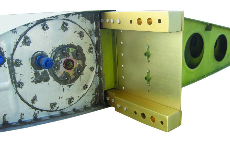
A typical section of the Xenos spar shows the spar caps (in yellow), the spar web (layered in the middle), and the clips that will act as rib attachment points during the wing build.
The Xenos Spar
This article is slanted toward metal wings and spars because the next time around, we’ll begin looking at the detailed construction of a typical metal spar—that intended for the Xenos motorglider. Longer than you’d expect for a typical sport plane, it is large enough to show examples of the many kinds of details you’ll find on any metal spar and is a good example of how the loads—and therefore the structure—change as you go from root to tip. The web is carefully built up out of different layers, which diminish from root to tip, and it has special mounting locations for controls and large bellcranks for the speed brakes. It also is constructed with carefully tapered spar caps, top and bottom. The entire structure is held together with 5/32-inch rivets, and their length and type change as you move down the structure. Flush rivets are needed near the root, where the two spars overlap in the fuselage, and round-head rivets are used elsewhere because they are quick to install without the need for countersinking and dimpling.
The Xenos spars have a little of everything (except for composites), and we invite you to follow along as we continue to explore the heart of the wing—the main spar.


Paul, Nice article, but you imply that the web is just there as a spacer keeping the spars apart. You show the “neutral force” line running along the middle of the web. While that is true, it is also true that this is the point of maximum shear stress in the direction of that “neutral force” line. In fact, the web of some I beam designs actually increase in thickness near the middle to support this shear stress. Looking at it another way, the top half (in compression) is pushing one way, and the bottom half (in tension) is pulling the other way and the only thing preventing the web being ripped down the “neutral force” line is the shear strength of the web. I just thought your readers should be aware that their are significant forces that the web must deal with.