For a few months, we’ve been concerned with the heat generated by our voltage regulators and lamp dimmers. Here’s a relatively elegant way of getting rid of unwanted heat that also provides a way of controlling the “get rid of” part if we’d like just a little heat to make things operate optimally.
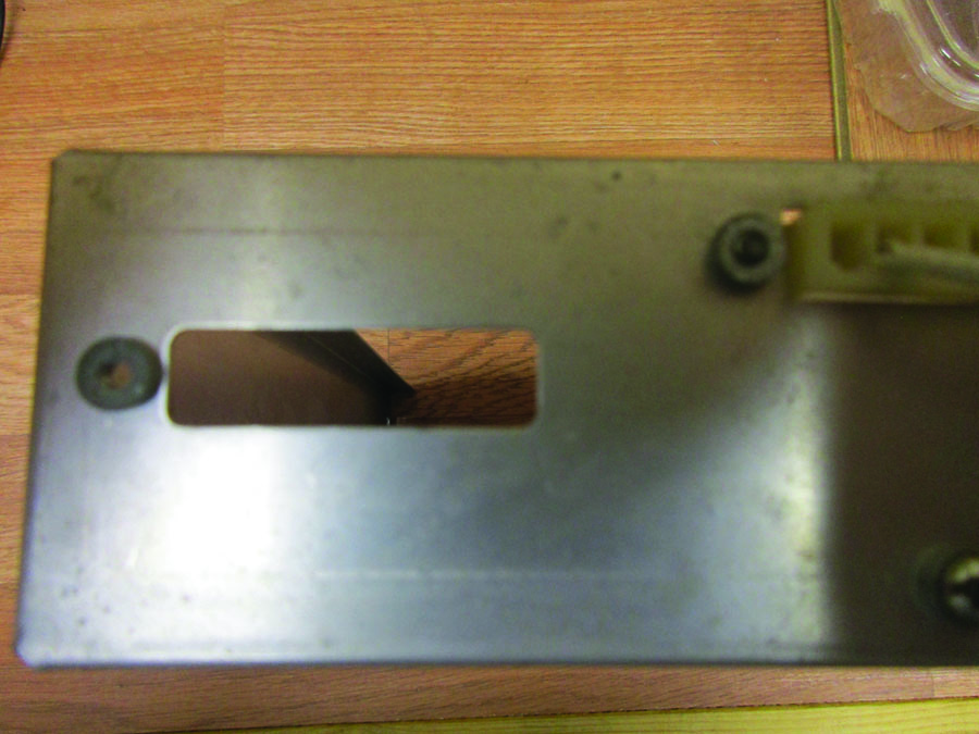
It was nice of Narco to leave this extra hole in the back of their transponder chassis for me to use as a cold air duct. Nice of them also to leave an extra press-nut for me to attach the temperature sensor.
It is also true that one of the inescapable facts of the thermodynamic laws is that heat flows from a warm body to a cold body. “Body” is a relative term here. All our body needs is some cool mass in close contact with the warm body. Now, you may not think of air having mass, but it does. It takes some effort to get that air mass to move around the warm body to cool it down.
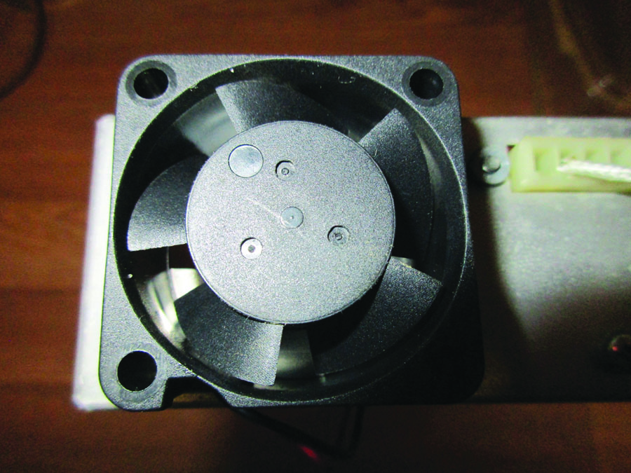
A 40-millimeter fan exactly fits most standard transponder chassis as well as a lot of com and nav radios. Jameco Electronics is an excellent source for small 12-volt fans.
All that malarkey says is that I want a way to blow (relatively) cool air on a part that is getting too hot. But I don’t want to blow cool air so much that the part is running too cold. It doesn’t take a great leap of faith to recognize that the easy way to blow air is with a fan. The problem is how to turn the fan on when the device is running warm and shut it off when the desired temperature is reached. In electronics we normally use 27 C (about 80 F) as the “bogey value” or the design center value for our components. What I’d like to come up with is a way to turn the cooling fan on at about 27 and turn it off at 22 (about 71 F) or so. That should keep our electronics working just fine for a long time.
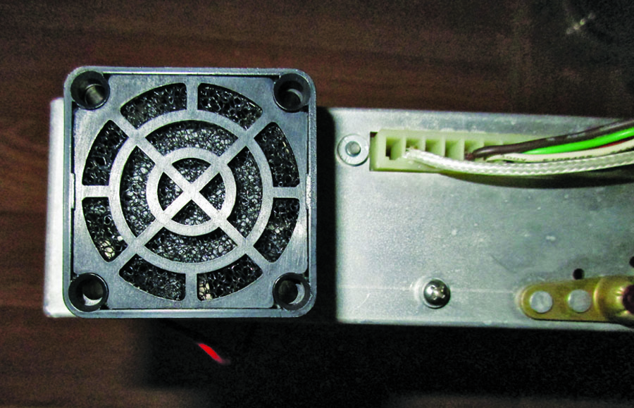
You can also get an air filter/finger guard for 40-millimeter fans from the same source.
You can also get 20-millimeter fans, but they don’t blow a lot of air.
There is an old rule of thumb that each 10 rise in temperature cuts the life of a component in half. What there has never been is a rule like that for cold. We know for a fact that silicon has a “best” operating temperature where the internals of the transistor are at optimum. Above and below this relatively wide range of temperatures, the current gain, diode temperature drift, and about a dozen other parameters start varying, some in concert with others, and others making things worse.
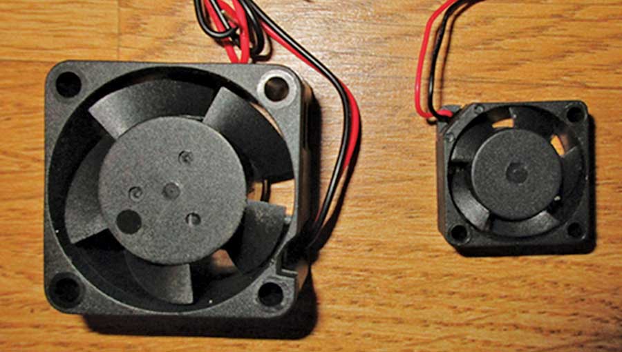
The 40- and 20-millimeter fans side by side.
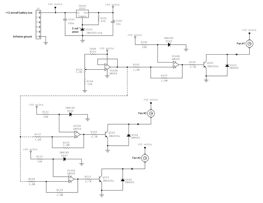
Here, in a nutshell, is how this project works. The 10-volt power supply (U101 and components) is very important to the operation of the device. We are going to be distinguishing between a dozen or so millivolts to get this rascal working properly, and it is mandatory to have a stable reference source. The devices that control stability are U101 itself and D101, a 5-volt Zener diode.
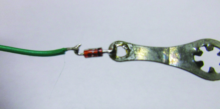
A diode temperature sensor mounted to a #4 solder lug for heat transfer.
D102 is the temperature sensor. It turns out that silicon diodes have a perfectly straight voltage-temperature curve. We are going to take advantage of that curve to have D102 sense the temperature of the device we are going to cool. The circuit as shown with R106 running less than a milliampere of current through D102 pretty well assures that we won’t be generating much (if any) heating in D102 to throw our calibrated temperature off.
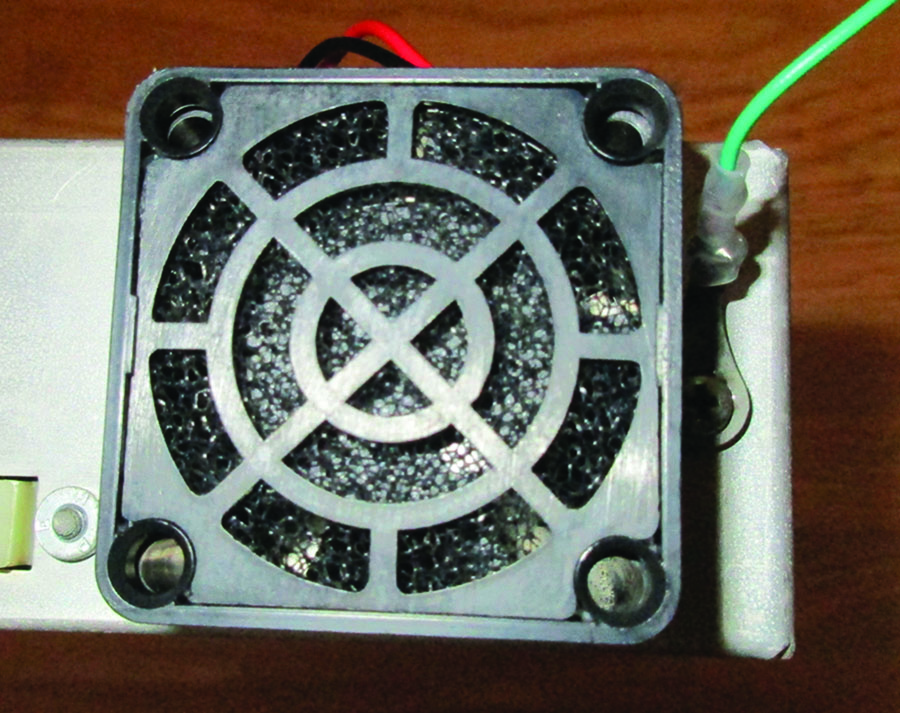
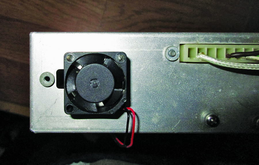
The fan mounted to the rear of the transponder case with the diode temperature sensor bolted to the right. Note the heat shrink on the diode.
The rest of the circuitry around U102A and U102B simply compare the voltage of D102 to a voltage set by R102 (“temperature set”) and turn on Q101 to provide a ground that turns the fan on and off.
U102C and U102D are simply carbon copies of U102B to control more than one fan (if that’s what you want to do). If you only want one fan, you can certainly substitute a 2-section amplifier like a LM358 for the LM234 if you wish and eliminate all the circuitry in the lower left quadrant of the schematic…all the stuff below the dotted line.
This fan controller should turn the cooling fan on at about 27 C (about 80 F) and turn it off at 22 C (about 71 F) or so. That should keep our electronics working just fine for a long time.
Rather than go into a long song and dance about what each component does, I’d like to take you on a little trip about what can go wrong with this fan controller.
1. Your temperature sensing diode may not have exactly the same temperature characteristic that mine has. I ran through a couple dozen diodes out of my stock, and they all agreed within a couple of millivolts. However, they all probably came from the same “dye bath” batch and should be exact duplicates of one another. I can’t guaran-tee that your batch will be exactly like mine, and there may need to be some “adjustments” to resistors R103 and R104 (see below). How to get around this? Well, Walmart (yes, that Walmart) has a bag of 500 diodes for $5. When Walmart got into the semiconductor business, I’m not really sure, but out of a bag of 500, you ought to be able to find one that is reasonably close to our test sample.
2. Your resistors R103 and R104 may be well within their rated nominal 5% tolerance, but if you look at the voltage-temperature curve of the diodes, it looks like you are trying to measure a voltage that varies between 535 and 545 millivolts from full on to full off. That is a 10-millivolt change out of a 540-millivolt center voltage, or a little less than a 2% change. Not only that, but a worst-case scenario puts R103 5% high and R104 5% low (or vice versa) for a 10% variation.
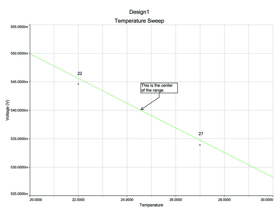
The curve of the voltage across a forward biased 1N4148 diode as a function of the temperature of the diode.
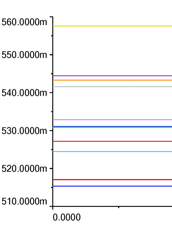
A “Monte Carlo” run of 5% resistors using only 10 tries. Note that the voltage at the center of R102 varies from a low of 515 millivolts to a high of 560 millivolts.
Take a look at the images showing what you might expect for randomly chosen R103 and R104 resistors. This is what is called a “Monte Carlo” analysis. The idea is to take random values for these two resistors within their respective tolerances and see what the output voltage of U102A is for these two random resistor values. Then do it again. And again. And again a few dozen times (the beauty of computer calculations versus slide rules). You can see that for 5% resistors, you could have a voltage as low as 500 millivolts (way too low) or as high as 590 millivolts (way too high). While the majority of the lines fall very close to our desired 540 millivolts, a lot of them are way off. Even if you buy precision 1% resistors, you have odds (Monte Carlo, remember?) of having 500 to 555 millivolts with end-of-tolerance resistors.
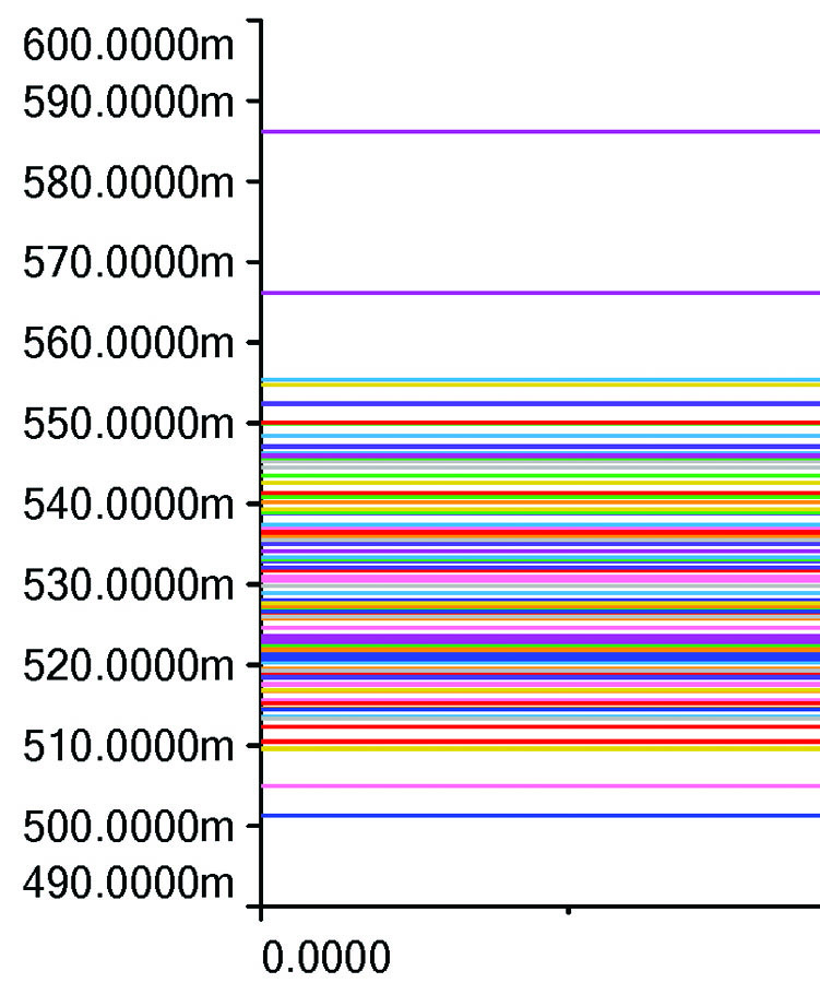
The same Monte Carlo run of 5% resistors but with 100 tries. The voltage now goes from 501 to 588 millivolts. This is because with more analyses, the odds of finding wider variations get much better. The graph of 1000 runs does not vary significantly from the 100 runs.
There are several options:
• Take a batch of 240k resistors and hand-select one that is closest to 240kΩ measured by a good ohmmeter. Do the same for a batch of 13kΩ resistors. Or…
• Set R102 to exactly mid-scale and measure the voltage at the output of U102A. If it is too low, bridge R103 with high-value resistors (I’d start at 4.7MΩ or so) until the voltage is 540 millivolts. If it is too high, bridge R104 with high value resistors (I’d start at 470kΩ or so) until the voltage is 540 millivolts. Or…
• Increase the value of the temperature-set resistor R102 to 5kΩ or even 10kΩ. The higher the value, the harder it is to accurately set a precise temperature, but it eliminates fooling around with bridging resistors. Or…
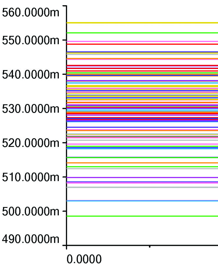
The Monte Carlo run with 1% resistors in place of the 5% resistors. This tightened up the spread a little (500-555 millivolts) but is still not good enough for production without some other changes.
• Select a diode out of your Walmart bag that matches the resistive divider values that you have.
Me? It all depends on what I’m doing. If I’m building just a one-off by myself, I’ll probably use the bridging technique. If I’m designing one for production and each one has to pass quality control without tweaking, I’ll use 1% resistors and increase the value of R102 to 5kΩ. If I have all the time in the world and just want to play around, I’ll try and find one diode out of half a thousand that will work with the resistor values I’ve got.
Until next time…Stay tuned…

![]()
Jim Weir is the chief avioniker at RST Engineering. He answers avionics questions in the Internet newsgroup www.pilotsofamerica.com-Maintenance. His technical advisor, Cyndi Weir, got her Masters degree in English and Journalism and keeps Jim on the straight and narrow. Check out their web site at www.rst-engr.com/kitplanes for previous articles and supplements.


s")


