Last month, we started to look at the way the airports an airplane is expected to operate from affect the design. The need to get into and out of these sites safely will often drive the design and cause it to differ significantly from a configuration optimized for the up-and-away part of the mission. We began with a look at the effects of runway length. We now turn our attention to another characteristic of the airport that must be taken into account.
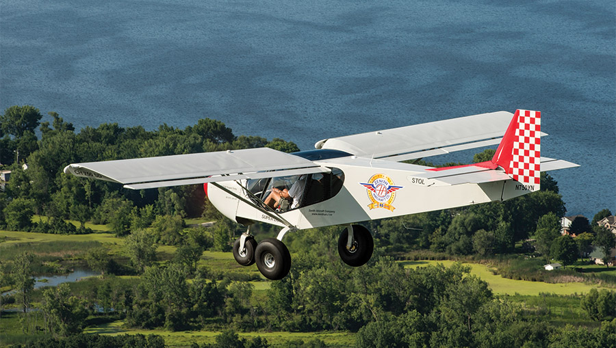
STOL airplanes like the Zenith CH 750 Super Duty typically feature large, effective flaps and also have high power-to-weight ratios.
Obstacles
Not all airports are surrounded by flat, featureless terrain. At most airports, there are obstacles off at least one end of the runway.
To land, the airplane must first clear the obstacles off the approach end of the runway and then descend to land. The slope of the approach is often defined by obstacle clearance.
When taking off, the airplane must be able to climb over the obstacles off the departure end of the runway.
Obstacles can be as small as an airport boundary fence or much higher objects like walls, trees, buildings, or terrain. For certification purposes a “standard” obstacle is taken to be 50 feet high, and takeoff and landing distances are normally quoted for trajectories that clear this standard obstacle.
Takeoff and Climb
After liftoff, the airplane must climb away without hitting any obstacles. The initial obstacle-clearance climb segment is different than the normal up-and-away climb. For the latter, we normally think in terms of rate of climb. What matters is how quickly the airplane can gain altitude.
For obstacle clearance, what matters is the angle of climb or the gradient of the flight path. What we care about is not how long it takes to get to altitude, but how far over the ground the airplane travels for each foot of altitude gained. Accordingly, both the vertical speed (rate of climb) and the horizontal speed (true airspeed) matter. For a given rate of climb, the faster the airplane flies, the flatter the flight-path angle and the longer over-the-ground distance it will take to get to a given altitude.
Figure 1 shows the effect of airspeed on angle of climb for an airplane climbing at 500 feet per minute. At 30 knots, which might be typical of an ultralight, the climb angle is about 91/2 degrees. By the time we are out to the 70 knots typical of a Cessna 150, the same rate of climb gives a 4-degree flight path slope. For faster airplanes, the climb angle decreases further, with 90 knots giving a 3-degree flight-path angle and 100 knots yielding only about 2.8 degrees.
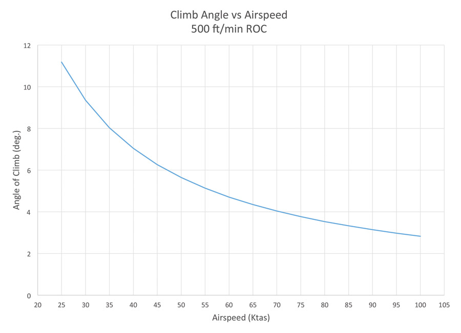
Figure 1: For a given rate of climb, as airspeed increases, angle of climb decreases.
The effect of this phenomenon on ground distance to clear a 50-foot obstacle is shown in Figure 2. Our 30-knot ultralight clears the 50-foot obstacle 303 feet downrange from liftoff. The 70-knot C-150 takes 708 feet to clear, and an airplane that climbs 500 feet per minute at 100 knots takes just over 1000 feet of horizontal distance to get to 50 feet.
This phenomenon has several interesting implications. The best angle of climb speed (Vx) for a given aircraft is always slower than the best rate of climb speed (Vy). Reducing speed somewhat from Vy to Vx reduces rate of climb, but the reduction in over-the-ground speed increases the flight-path angle.
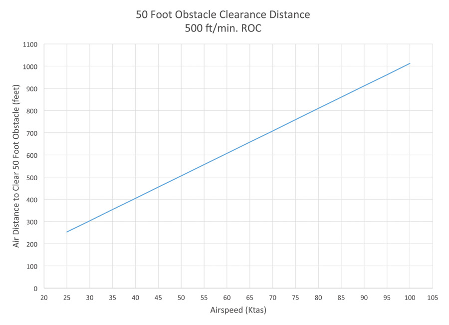
Figure 2: As airspeed increases, more distance is needed to clear a 50-foot obstacle.
For short-field operations over obstacles, it is desirable to climb at a low airspeed. Notice in our example that the ultralight took less than half the distance to clear the obstacle than the Cessna 150 even though they are both climbing at the same rate in feet per minute. For the designer, this means that a need to clear obstacles in a short distance will tend to drive the airplane toward lower wing loading than would otherwise be optimal.
The advantage of flying slowly in an obstacle-clearance climb may also drive the design of the flaps. Using some flap deflection to increase the maximum lift coefficient of the wing will allow the airplane to fly slower while preserving an acceptable margin from the stall. The tricky part for the designer is that flaps also produce significant drag. The extra drag of the flaps reduces the excess power available and therefore reduces rate of climb. If the flap drag is too high, the reduction in rate of climb overpowers the reduction in climb airspeed, and obstacle clearance distance is increased rather than decreased.
This dichotomy is why dedicated STOL airplanes typically feature large, effective flaps and also have high power-to-weight ratios; the extra engine power is needed to overcome the drag of the extended flaps.
For less extreme airplanes, using flaps that are reasonably low drag at small (15 degrees or less) deflections can often provide a useful reduction in distance to clear an obstacle. Even for such relatively efficient flap systems, the flap drag is significant, so this approach is not typically effective for lower-powered airplanes.
Climb angle or climb gradient can also be an issue for multi-engine airplanes. Multi-engine airplanes typically are aimed at the higher performance regime, and accordingly tend to have relatively high climb airspeeds. With one engine inoperative (OEI), the combination of the reduced rate of climb due to the loss of power and the high climb airspeed tends to make the climb angle quite flat and greatly increase the distance required to climb over an obstacle.
U.S. certification regulations for transport airplanes (FAR Part 25) include minimum climb gradient requirements as well as minimum rate of climb requirements. This climb gradient requirement can end up sizing the engines so the airplane has sufficient thrust to maintain an acceptable climb angle. In some cases, it may also dictate the number of engines. Regulations apply to a situation with one engine out. The more engines the airplane has, the smaller the percentage of total thrust that is lost due to the failure of a single engine. In some cases, a twin will have to be so overpowered to meet climb gradient requirements that it becomes too inefficient in cruise. Going to three or four engines allows the airplane to have a lower thrust-to-weight ratio with all engines operating and still meet OEI climb requirements.
Approach and Landing
On approach, the airplane must clear the obstacle and then descend to the ground to land. As with the obstacle-clearance climb after takeoff, what matters is the slope of the flight path, not the time rate of change of altitude.
Unlike with climb, airspeed does not play a primary role in determining approach slope. What matters instead is the effective lift-to-drag ratio (L/D) of the airplane. In order to decrease the distance between the obstacle and the touchdown point, we need to steepen the approach by reducing the L/D of the airplane.
Some relatively simple low-performance airplanes have steep enough glides that they do not need any additional drag device to have an acceptably steep approach slope. Open-frame ultralights, for example, can approach quite steeply because they have relatively high parasite drag. Accordingly, by flying a little faster than best L/D airspeed, they can essentially dive at the ground without overspeeding. Somewhat lower-drag airplanes may still avoid the need for extra drag devices by using a sideslip maneuver to increase drag and steepen the approach.
Once an airplane is clean enough to have decent cross-country performance, its clean-configuration glide slope is flat enough that it requires a long distance between an obstacle and touchdown. This characteristic was often cited as a disadvantage of the cantilever monoplane configuration in the pre-WW-II era, when the competition between the biplane and the monoplane was still underway. Some early monoplane designs were lauded for their cruise performance, but were considered to be difficult and dangerous to land because of the flat glide and high approach speeds that resulted from trying to fly approach slopes more typical of higher-drag biplanes.
The solution to this problem is to provide variable geometry that allows the pilot to increase drag and steepen the approach. The most common device for doing this is a set of high-lift flaps. On most flap systems, the last 10 to 20 degrees of deflection (depending on max deflection) have very little effect at increasing maximum lift, but add a lot of drag, which steepens the landing approach.
The right size and maximum deflection of the flap system is a trade between the need to add lift and drag to the airplane for landing approach, the weight and complexity of the flap system itself, and the need to be able to execute a successful missed approach.
The ability to go around after a missed approach is a major determinant of how much flap drag is acceptable. In the initial stages of a missed approach, the pilot cannot retract the flaps suddenly to reduce drag because the loss of lift will stall the airplane. Because of this, the airplane must have enough power to arrest the sink rate and establish a positive rate of climb with the flaps still in the approach/landing position. Only after the climb has been established and airspeed increases somewhat can the flaps be progressively retracted to clean up the airplane for best climb performance.
As we saw for takeoff, this means that airplanes intended for STOL operations will typically combine large, effective flap systems with high power-to-weight ratios.
The need to take off and land over an obstacle has major effects on the configuration of the airplane, as we have just seen. Next month, we will look at how the characteristics of the runway surface itself affect the design.

![]()
Barnaby Wainfan is a principal aerodynamics engineer for Northrop Grumman’s Advanced Design organization. A private pilot with single engine and glider ratings, Barnaby has been involved in the design of unconventional airplanes including canards, joined wings, flying wings and some too strange to fall into any known category.


