The stability and controllability of an airplane are strongly affected by the geometric relationship between the center of gravity (CG) and the aerodynamic center of the machine. It must balance properly in order to fly successfully.
As the designer develops the configuration of the airplane, the CG position and its travel are established. Every mass that is part of the airplane or aboard at takeoff affects the position of the CG.
In order to get the airplane balanced properly, the designer must first establish the CG of the empty airplane and then define the positions of the variable loads (crew, passengers, payload, fuel, etc.) that the airplane will carry.
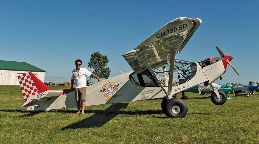
No, this Zenith CH 750 Super Duty doesn’t have a balance problem. Sebastien Heintz, president of Zenith Aircraft, is simply demonstrating how easy the airplane is to move around on the ground by pushing down on the aft fuselage.
Empty CG
For most airplanes, weight of the empty airplane is 50% or more of the takeoff gross weight. Accordingly, the position of the CG of the empty airplane is of critical importance in the balance of the machine. The empty CG is determined by the configuration of the airplane, but each type of configuration tends to have the CG in a different place.
The designer has surprisingly little freedom to move the CG around once the basic configuration of the airplane and its major components are decided. Each component’s individual CG falls in a specific place on the component itself, and the overall configuration of the airplane severely limits how the components can be moved relative to each other to move the CG.
For the moment we will limit our discussion to single-engine propeller-driven airplanes, although the basic principles will apply to other types also.
Engine
The engine accounts for 20 to 30% of the empty weight of a typical light airplane. It is a concentrated mass and must be able to drive the propeller, which itself weighs 2 to 3% of the total airplane empty weight. If the prop is driven directly by the engine, as is the case for most airplanes, the engine/prop combination ends up being one-quarter to one-third of the total empty weight of the airplane. Because this is such a large percentage of the total empty weight, the CG of the empty airplane will be pulled toward the CG of the engine.
Fuselage
The CG of the fuselage will tend to be close to its midpoint. While details about the shape of the fuselage and where it is reinforced to take concentrated loads like engine mounts, seats, landing loads, and wing attach loads will move the CG a little, a typical fuselage is a relatively uniform structure with its mass distributed continuously along its length. Its CG will be near its 50% length point, and there is little a designer can do to change this. Once the length of the fuselage is set, its CG position is essentially set also.
Wing
The center of gravity of a wing tends to be at about 40% of its mean aerodynamic chord (MAC). This is slightly forward of the centroid of area of the wing (50% MAC) because the primary spar structure or wing box is biased forward in the wing to place the spar at or near the maximum thickness of the airfoil and to align the elastic axis of the wing with the aerodynamic center of the wing so the wing does not twist when it bends under air loads. The forward bias of the spar structure moves the wing CG forward somewhat from the centroid, which is also the CG of the wing skins. While the designer may move the wing fore and aft to affect the balance of the airplane, this is done for aerodynamic reasons, not to move the CG of the mass of the wing. Accordingly, the wing will be placed after the CG of the fully integrated fuselage, including seats, systems, engine, and tail surfaces, has been located. While the mass of the wing must then be taken into account in the determination of the CG of the complete airplane, the wing CG itself will be close to the target CG of the complete airplane, and the wing position will not cause the CG to move much. (Note that this is not the case for canards and tandem-wing configurations where the wing weight is usually significantly separated from the desired flight CG, and changes in wing weight and position can cause significant changes in the airplane’s empty CG.)
Tail Surfaces
The designer has even less freedom to make changes to the tail surfaces to affect CG. The size and position of the tail surfaces are dictated almost entirely by the aerodynamic effects required to give the airplane acceptable stability and control characteristics. The mass of the tail surfaces is not variable either. It is dictated by a combination of the need for structural integrity and the mass of the balance weights required to avoid flutter of the control surfaces.
Even though the weight of the tail surfaces cannot be directly varied to alter CG, it is important to keep a close eye on it during preliminary design. Because the tail is mounted at the extreme aft end of the airplane, it is a long way away from the CG of the complete airplane. The same long moment arm that gives the tail the aerodynamic leverage to stabilize and control the airplane also gives the mass of the tail a disproportionately large leverage on the CG position of the airplane.
Because the tail has one of the largest effects per unit of mass on the CG, getting the estimated weight of the tail right is very important in preliminary design. It is very easy to underestimate the weight of any airplane component, partially because it is easy to overlook small items that add up (like hinges, control horns, etc.) and partially due to the natural tendency to be optimistic in our initial design assessments. The problem with underestimating the weight of the tail is that the extra weight of the tail will pull the CG aft significantly, and the airplane will be tail-heavy relative to the initial CG estimate. Because the tail has so much leverage on the overall airplane, the modifications one must make to get the CG back where it should be after the airplane has been built are disproportionately large.
I have had his very experience on one of my personal projects. On my Lightbeam ultralight design, I underestimated the weight of the tail by a few pounds. When the airplane was completed and weighed off, I found that the empty CG was significantly aft of where it was supposed to be. Before the airplane was first flown, I had to completely revamp the installation of my BRS parachute system, moving the ‘chute and its can well forward on the airframe and reroute the parachute risers in order to bring the CG within limits.
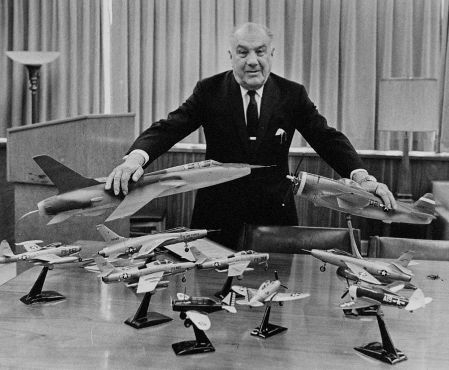
Alexander Kartveli, chief engineer at Republic Aircraft, shown with models of many of his designs. (Photo: San Diego Air & Space Museum Archives via Wikimedia Commons)
Ways to Adjust CG
The experience just recounted illustrates how one goes about adjusting the empty CG of an airplane. Ideally, this happens during the “paper” (or digital) phase of the design so that we don’t have to modify already-built structure or hardware.
As we have seen, the designer has remarkably few options available to alter empty CG. Most of the components of the airplane are either fixed for a good reason, or they produce larger aerodynamic than mass properties effects if they are moved. This leaves only a few options:
Engine Mount Length
The minimum distance between the firewall and the cockpit seats is determined by the need to accommodate the pilot, and the minimum length of the engine mount is typically determined by clearance between the engine accessories and the firewall. It is, however, relatively straightforward to move the engine forward by lengthening the engine mount. In the preliminary layout of a tractor-engined airplane, it’s a good idea to make the initial engine mount longer than the minimum length dictated by engine clearance from the firewall. This leaves two types of design flexibility: First, if the airplane turns out to be nose-heavy once it is completely defined, the engine can be moved aft to move the CG aft. Second, when the inevitable desire to put a bigger, more powerful engine into the next iteration of the airplane appears, there is room to move the new, heavier, engine aft to keep the CG within limits.
Another reason to start out with a slightly longer engine mount and err on the side of nose-heaviness is that it is a lot easier to move the CG of an airplane aft than it is to move it forward. The engine and firewall are much closer to the CG than the aft end of the tail cone, so moving mass aft in the fuselage moves the CG aft quickly, but there is no place that has similar leverage if we need to move mass forward. While it is possible to move the engine forward after the airplane is built, it is a major modification requiring a new engine mount, modified or new cowling, and replacement of engine control cabling and fuel lines.
The CG of an airplane design tends to creep aft as the design progresses, and lots of little weights aft of the CG grow. It is told that Alexander Kartveli, the chief designer of Republic Aircraft, would mount a block of lead to the tail post of each Republic fighter prototype as it was being built and challenge his engineers to make the airplane balance with the lead in place. The story goes that they could never actually succeed at this, and as the build progressed, they would persuade Mr. Kartveli to remove a little bit of lead at a time as the CG crept aft. By the time the airplane was finished, the CG would be in the right spot, and all or most of the lead would be gone. This was his way of hedging against the tendency of the as-built CG to be aft of the estimated CG. As designers, the lesson we can take from this is to target a CG forward of the most aft acceptable CG during design phase so we have reserve for when the CG moves aft.
Battery
The other mass that is relatively easy to relocate on an airplane is the battery. Moving the battery from just ahead of the firewall to aft of the cockpit or even farther aft in the fuselage can move the CG quite significantly. As we have already seen, because of the geometry of the airplane, there is much more room to move the battery aft to move the CG aft than there is to move it forward. The designer should make an early estimate of how much the battery position can affect the CG by choosing a most forward and most aft possible position for the battery box and then calculate the airplane CG with the battery in each position. This information will be very valuable in deciding where to target the CG initially, and where moving the battery can take it. It’s not uncommon for an airplane that can take a variety of engines to design a forward battery mount for the initial (smaller, more economical) engine installation and an aft battery box to keep the CG within limits when a builder installs the inevitable larger, heavier engine.
Next month we will continue our discussion of how the configuration of the airplane affects CG.


