
Having been formally trained as a grease monkey, I know the precarious nature of depending on a floor jack for both lifting and holding. You work under an automobile only after it is properly supported by jack stands. The same holds true for airplanes.
While the owner’s manuals for certificated aircraft will show the proper locations for lifting and supporting, with many experimental airplanes, not so much. Yet it’s more than occasionally we need to jack up the gear and remove the wheels, be it for brake inspections, bearing repacks, or tire changes.

The author’s Jabiru sat safe and sound for several days on these shop-built axle stands while awaiting new brake pads. The black pad between the stand and the axle is a piece of bicycle inner tube glued on with contact cement.
For about $25 at Harbor Freight, you can buy a set of automobile jack stands. Don’t! Jack stands for cars are too tall and the hockey-puck pads are completely useless for supporting aircraft legs or axles.
Aviation supply houses like Wicks and Aircraft Spruce have many different stands for airplanes, including axle stands similar to our project. While these are very nice, in addition to being expensive ($120+ for a pair), they’re also too tall, in my opinion, for most small, Light Sport airplanes.
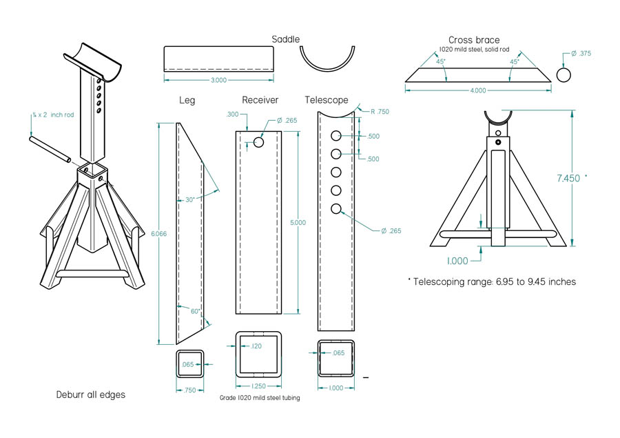
The pyramid design is best suited for thin-wall steel tubing. The U-saddle idea was driven by the short length of suitable tubing on hand.
The design of the commercially made “landing gear” axle stands (Bogert, if you’re interested) feature an H-frame base, a vertical post, and an adjustable telescoping segment with a tubular axle receiver. The tubular receiver allows you to hang the stand on the axle before lowering the jack. Very cooI. One could easily replicate the Bogert stand, but as often happens when working up ideas for gadgets or doo-dads for around the shop (especially the non-flying type), I end up designing based on material at hand, which at that moment was mostly thin-wall (0.065 inch/16 gauge) mild steel tubing.
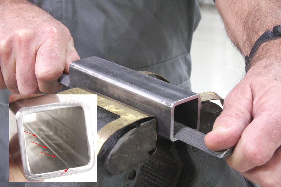
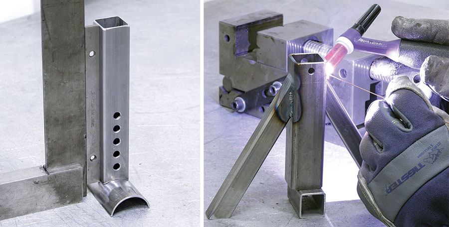
The center receiver was made from 11/4-inch, 0.120-wall, mild steel, square tubing. This size allowed for a perfect (for a jack stand) sliding fit with the 1-inch tube used for the adjustable telescoping saddle. All mild steel tubing is made with a noticeable weld seam on the inside. This seam might or might not interfere with the fit of the telescoping tube, but it’s a good idea regardless to file down the high spots so the jagged edges won’t (later on) scratch the paint.
This project is basic cutting and drilling, then welding. No special fixtures are needed, but it will require a one-inch spacer of some sort (I used a section of scrap one-inch square tube) and a machinist square to line up the center receptacle in place for tack welding. A square and a parallel are needed to T-up the saddle and telescoping tube.
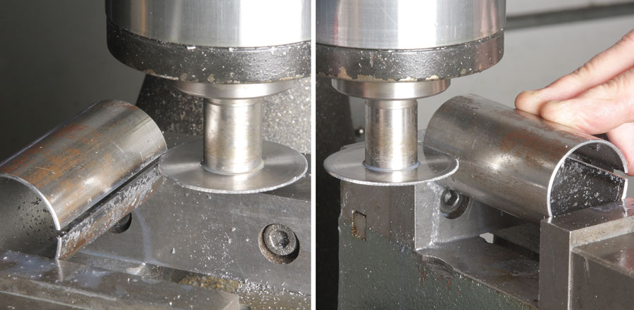
I used a slitting saw in the vertical mill to split a 3-inch length of 11/2-inch OD 4130 tubing into two saddles. Note how I used finger pressure to prevent chatter during the second cut. I could have used a hacksaw or a band saw, but a thin-kerf slitting saw is the cleanest way to cut a short length of tubing into two nearly perfect semicircles.
The diameter of axles on the airplane you intend to support is a key design consideration. The axles on my Jabiru are 1-inch diameter. I wanted the saddle to cradle the axle as snugly as possible. I had a section of 0.065-wall 1-inch OD 4130 tubing lying around, and after some figuring concluded that if I added a thin sheet of rubber (from a bicycle inner tube) to cushion the axle from the steel saddle, the fit would be close to perfect. The saddle doesn’t have to be an exact fit, but when building a stand (or set of stands) for a particular airplane, it’s a nice touch.

(Left) A 11/2-inch bi-metal hole saw was used to fit the saddle to the telescoping tube. Care was taken to make the cut exactly on center so the saddle would support the weight of the airplane evenly over the jack stand. (Right) Several 17/64-inch holes were drilled in the telescoping tube to accommodate a -inch quick-release pin. These holes, as well as the hole in the top of the receiver, have to be on dead center.
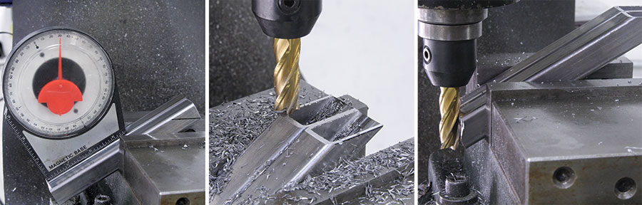
(Left) You don’t need a precision tool to set the angles for a project like this, but it is important they all be the same. I used an inexpensive magnetic angle finder and milled two legs at a time. (Center) Take small bites and nibble your way down to the full miter. Getting too aggressive on thin-wall tubing can cause the cutter to catch and ruin the part. (Right) To miter the base ends, I repositioned them in the vise, keeping the angle the same, but with as little overhang as possible.
Even though an airplane can’t roll while sitting on a set of axle stands, it could still topple if someone bumped the tail or, while working outdoors, a gust of wind were to hit. It’s a good idea to chock the third wheel and, if necessary, use tie-downs. One might also consider putting traffic cones (or trash bins) by the nose and tail to ward away anyone from inadvertently trying to move the plane. In the meantime, get out in the shop and make some chips!
A machinist square, a parallel, and a simple spacer were all that was needed to tack and weld this project. Many thanks to Billy Griggs for the high-quality TIG welds!
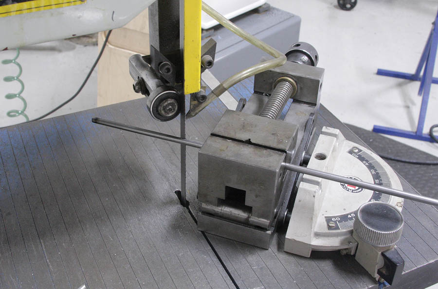
The 3/8-inch diameter cross braces proved to be a challenge to get the length and angles right. The ultimate solution was to use a vise and miter gauge, and cut them on the band saw.
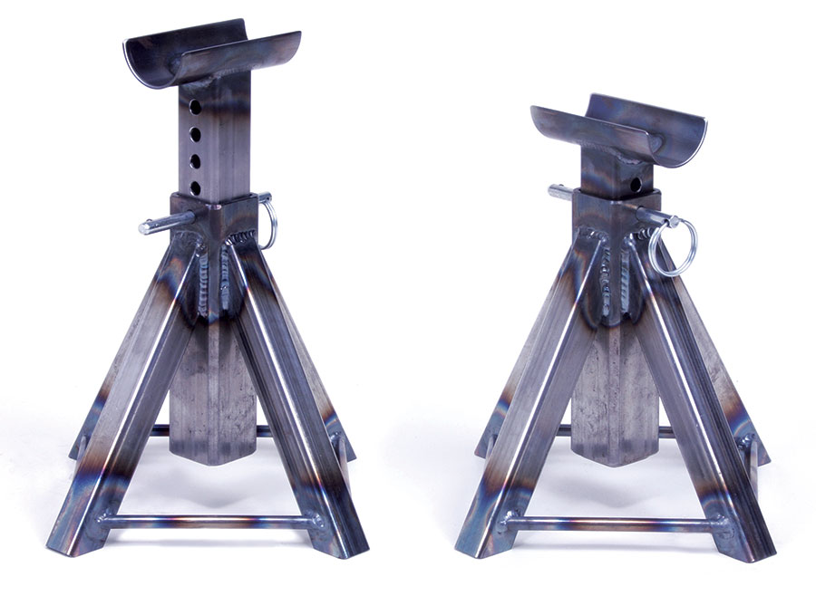
The welded stands before sandblasting, painting, and adhering the rubber pads.


