Last month we considered a digital meter that had a voltage range of 4-30 volts and a loadmeter current range of 0 to 10 amperes. Note carefully that I said loadmeter, not ammeter. The loadmeter measures how much of a current draw the airplane electrical system is using, while the ammeter merely shows whether or not the charging system (alternator) is keeping up with the load that the electrical system is using to power the radios, lights, and other electrical gizmos on the airplane. I also said that if I have a voltmeter telling me whether or not the alternator is keeping the battery charged, then I much prefer a loadmeter to tell me how much current is being drawn from the electrical system.
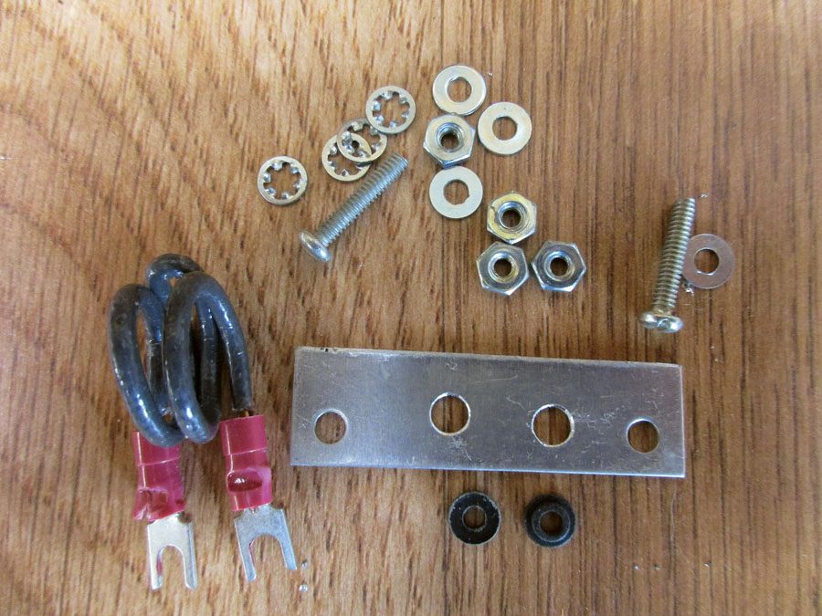
The 75-millivolt shunt parts (50 cents at the outside). From left to right, bottom to top: the shunt wire made from the black wire from a 7-inch length of Romex house wire, the aluminum mounting plate, the flat fiber washer, the shoulder fiber washer, and the #4 hardware to assemble the shunt.
I also said I’d amp up (pun intended) the design to deal with the same voltage range but take the loadmeter to a 50-ampere full-scale range rather than the 10-ampere range of last month’s design. I also intend to provide a little electronic help to put the shunt in either the negative supply lead (not easy in a metal ship) or in the positive lead. And I’ll explain how to make that shunt several different ways.
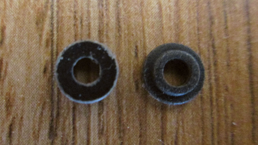
Flat fiber washer and shoulder fiber washer.
The meter requires a 75-millivolt shunt (0.075 volts) for a 50-amp full-scale reading. There are several ways of getting this small amount of current, but the easiest by far is just a plain old piece of wire. Once again, Brother Ohm tells us (R=E/I) that this shunt should be 1.5 milliohms (mΩ) of resistance. That is an awfully small resistor, so it isn’t going to take a lot of wire to make up that shunt. If you choose to make the shunt out of #14 copper wire stripped from a piece of Romex house wire, the wire table (see “Aero ‘lectrics,” March 2018) shows that a piece of #14 copper wire about 7 inches long is 1.5 mΩ.
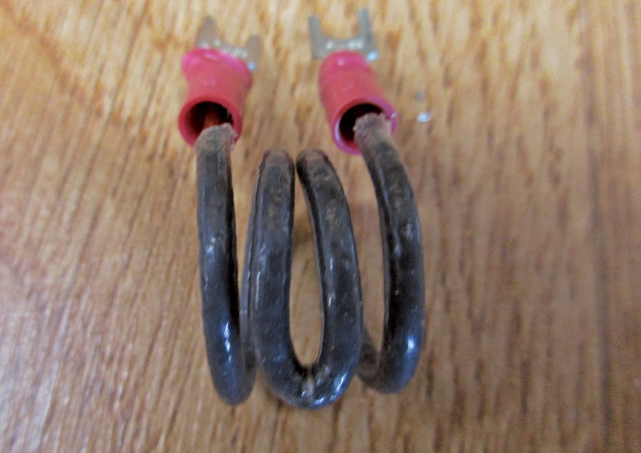
The Romex shunt wound as non-inductive. First half of the wire is wound clockwise and the second half counterclockwise. The inductances cancel and very little field is created to mess up things like compasses and pointer-type meters.
That’s a pretty long wire, but we ought to be able to shorten it up a bit. First of all, you can coil it up with no problems so long as adjacent turns are insulated from one another. Or you can make it out of something that is a poorer conductor than copper. For example, if you choose to make it out of #14 aluminum wire, it would only be 2 inches long. Brass would be 0.8-inch long, and steel fence wire would be a microscopic -inch long.
Of course, you can always use a thinner wire to increase the resistance. If we stay in copper, a #18 wire would only be 2 inches long, a #20 wire would be 1 inch long, and so on. The gotcha here is that while #14 can handle 165 amps before melting, that #18 would melt at 82 amps (probably still OK), but #20 would melt at 58 amps, which is pushing the limit just a bit for my tastes.

Voltmeter-ammeter-loadmeter installation schematic.
In any case, that wire is going to get warm. At full current it will be dissipating nearly 4 watts of power. That’s not a lot of power, but enough to melt any plastic or fabric part it is touching. I’d probably want to use a little fiberglass sleeving on the wire. If I’m using Romex then I’d leave the insulation on the wire. That shouldn’t be enough to melt the wire, but let your safety angel be your guide.
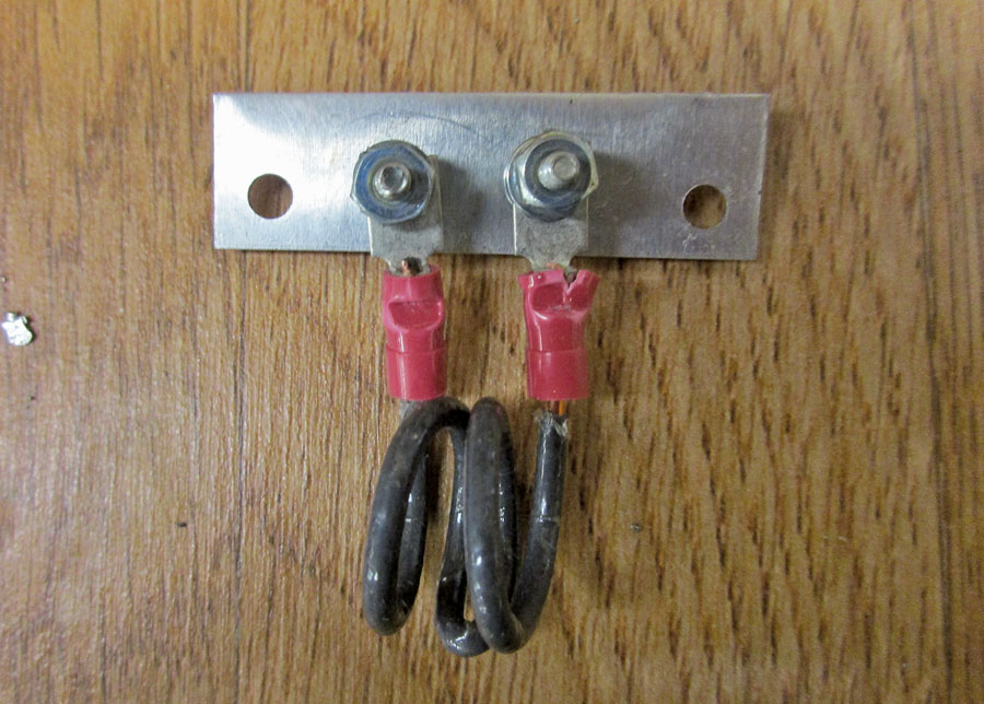
The final shunt assembly.
Mechanically, how do I make that shunt? Ah, your friend that makes this all work is something you probably have never seen: a shoulder washer. Specifically, a fiber shoulder washer. Why not a nylon shoulder washer, which is a little cheaper and easier to come by? Nylon melts; fiber chars. In the event of a super over-temp, when the nylon melts, the center bolt can move to touch the chassis, making the situation worse. When fiber over-temps (and it has a relatively high temperature rating) it chars, but the insulating shoulder is the last thing to go, protected from direct heat by the bolt and the flat washer.
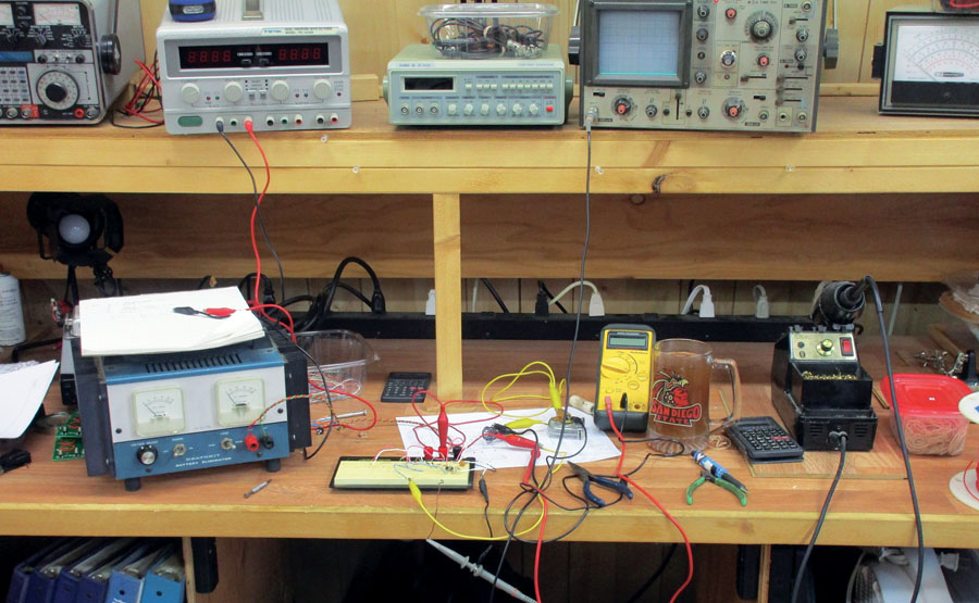
What the workbench looks like after a 2 a.m. final test. The iced tea in the San Diego State University mug is the only thing keeping me awake.
The whole assembly is made up of a bolt (or machine screw), flat washer, flat fiber washer, fiber shoulder washer, flat washer, lock washer, nut, flat washer, crimp terminals, flat washer, lock washer, and nut. The clever amongst you have already said in your mind, “Ah-ha, that would make a pretty spiffy firewall feed-through, wouldn’t it?” Yeppers, it sure would.
We’ve learned how to make an elementary shunt; let’s now consider how to install it. In the method we saw last month, the shunt was installed in the negative power lead of the battery to the load. That will also work for this shunt, but most aircraft installations require that the shunt be installed in the positive lead of the electrical system. This allows the skin of a metal airplane be the negative return (or ground, or whatever you want to call it), and the positive lead is run to the load. That is the same thing for nonconductive ships as the alternator is generally connected to the engine, which in turn is connected to the ship’s ground/negative supply network.
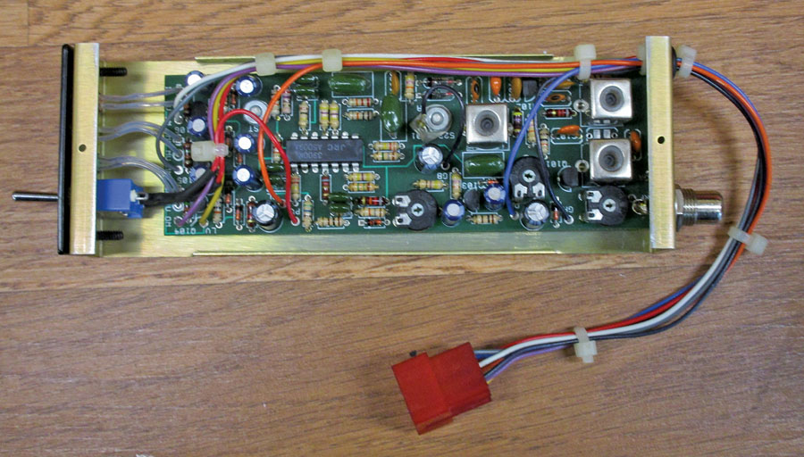
Close-up of the “guts” of the project.
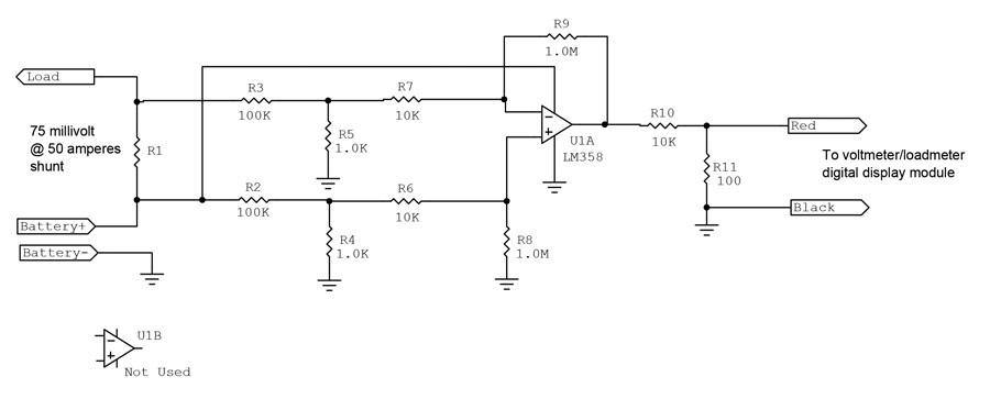
So how do we install the shunt in the positive lead? It requires about 50 cents’ worth of parts and a relatively trivial design. It goes by different names such as instrumentation amplifier and differential amplifier. The circuit given in the schematic is simply one section of an integrated circuit operational amplifier with the resistor values chosen to set the gain of the amplifier to 100. Thus, a 75-millivolt full-scale voltage at the shunt will provide 1700 millivolts (7.50 volts) at the output of U1A, one of the two sections of the op-amp chosen. The two output resistors drop this relatively large voltage down to the 75 millivolts of the shunt wires on the meter.
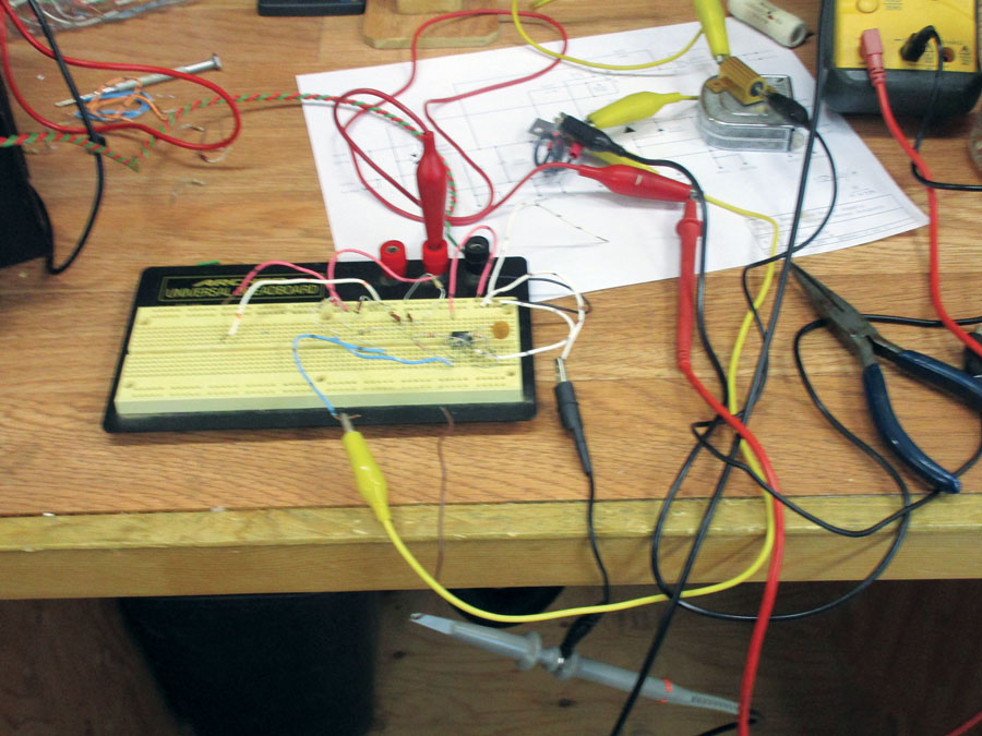
similar project that was haywired up for breadboard, but in production we made it pretty enough to put in your airplane.
The op-amp chosen, an LM 358, is an old workhorse that works well with output voltages within a couple of millivolts of ground. Thus, our output will go smoothly from no current to full current with little difficulty.
I must admit in closing, I’ve used diff amps in a hundred places in my design career, but this is the first time I’ve ever had to take it from millivolts low side to volts and then back to millivolts to go from high-side sense to low-side sense with good accuracy and in phase (up-to-up and down-to-down). You may think that comes with the territory. It doesn’t. I’m indebted to my editor who allowed me nearly a week of grace to do research and investigation on something that not only have I never done before but has never been discussed in any data sheet or design notes that I could find. You truly have a unique design that nobody has ever seen before (at least nothing that has been written about).
The schematic of the meter driver for high-side shunt.
Next month (or perhaps in a month or two) another “sensor” for this project that doesn’t depend on a wire length, but simply uses the straight aircraft supply wire, a cheap ferrite toroid, and the exact same diff amp circuit to make a shunt for our digital meter but without having to make a wire shunt or losing 75 millivolts in the process. It will involve a cheap hall-effect sensor to detect the magnetic field around the primary wire powering all the electric/electronic devices on your airplane.
Moderately difficult to make and assemble, but not for my readers who are amongst the cleverest and handiest on earth. Until then, stay tuned…


s")


