Last month, we discussed the aerodynamic design and construction of gear fairings. This month, we’ll take on wheel pants. We’ll start with some aerodynamic considerations: Whereas gear fairings represent a 2D extrusion, pants are more similar to 3D bodies of revolution. But as noted in our discussion on fairings, simply using a 2D wing airfoil as the outline for a pair of wheel pants is probably far from optimal. The best approach is computational (i.e., CFD analysis), but we’ll assume that is beyond the means/skills of most homebuilders.
Fortunately, we can thank a Brazilian aerodynamicist, Francisco Galvao, for proposing a theoretical approach that, based on pants actually made using his method, seems to work pretty well. According to Galvao, we can simulate 2D airfoil pressure distribution in a 3D body of revolution by taking the y axis coordinates to the 3/2 power. For example, a 10% thick symmetrical foil with transition from laminar to turbulent flow at 50% chord, when transformed by Galvao’s rule, would yield a 22% thick profile for a body of revolution with transition at the same location.
The choice of foil to transform is not necessarily obvious. A good beginning point is Bruce H. Carmichael’s discussion of optimal aspect ratio for bodies of revolution. This will set the thickness of your profile to transform. Once you have determined thickness, you must then look through the catalog for an airfoil with characteristics you desire: appropriate thickness, degree of laminar flow, sensitivity to off-angle operation, and type of pressure recovery. Being too aggressive (say, aiming for 70% laminar flow) may yield a pant that is fantastic at one speed and pitch/yaw angle, but is otherwise overly draggy.
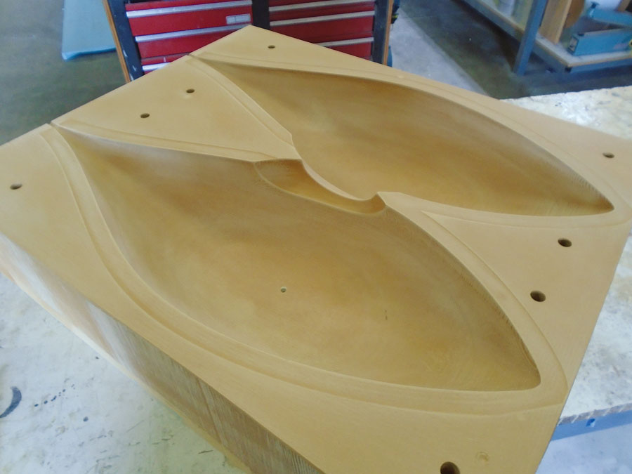
Mold construction and prep are the same as for the gear fairings discussed in Part 1 of this article.

Three layers of 6-ounce carbon cloth should be sufficient. Larger pants might need a bulkhead(s) in front of, or aft of, the wheel.
Wheel Pant Assembly from Left/Right Mold Halves
The following shows how the SR-1 speed plane wheel pants were constructed. I’ll be the first to admit that this is not necessarily the fastest way to make a set of pants, but it yields nice, well-fitting pants.
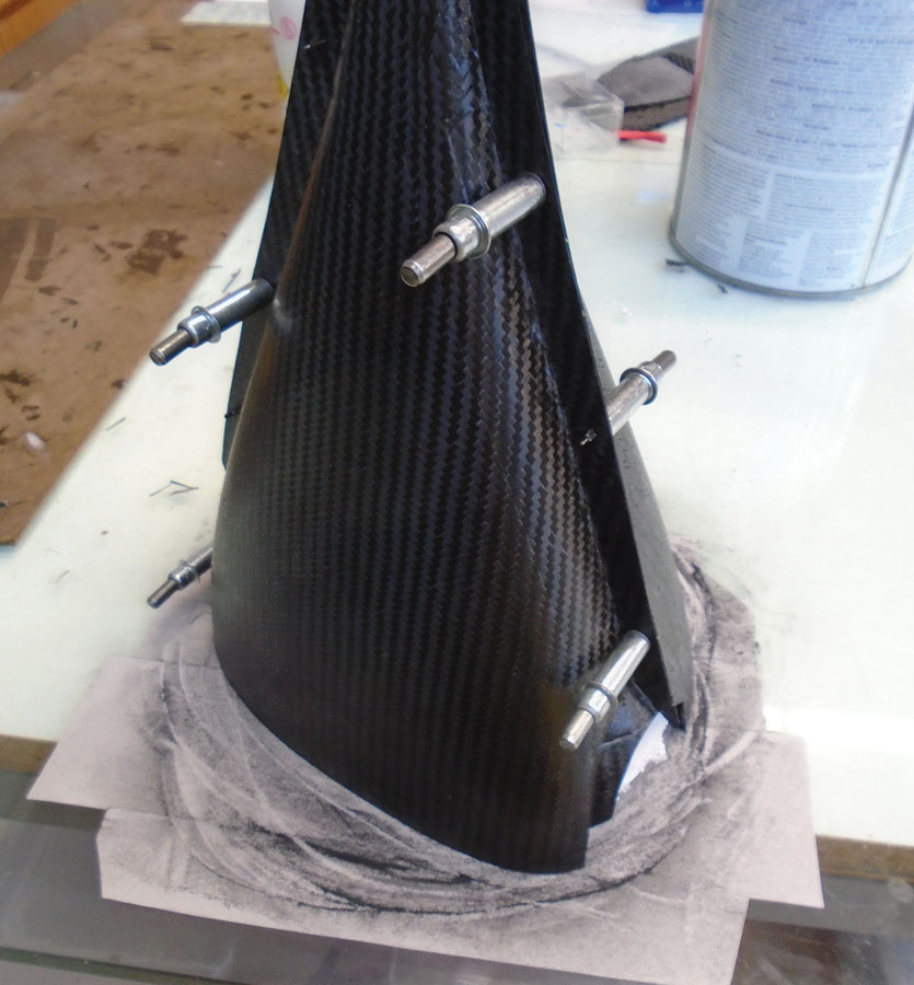
1. Mold construction and prep are the same as for the gear fairings discussed in Part 1 of this article, which appeared in the May 2019 issue. Note that when mounting the finished pants to the wheel, it’s very helpful to have the location of the axle centerline molded into the pant for accurate fitting. Three layers of 6-ounce carbon cloth should be sufficient. Larger pants will probably need a bulkhead(s) in front of, or aft of, the wheel to improve stiffness and reduce pumping losses and the amount of dirt getting thrown into the wheel well. A video of pants being vacuum bagged for the SR-1 speed plane can be seen at the SR-1 Project Facebook page.
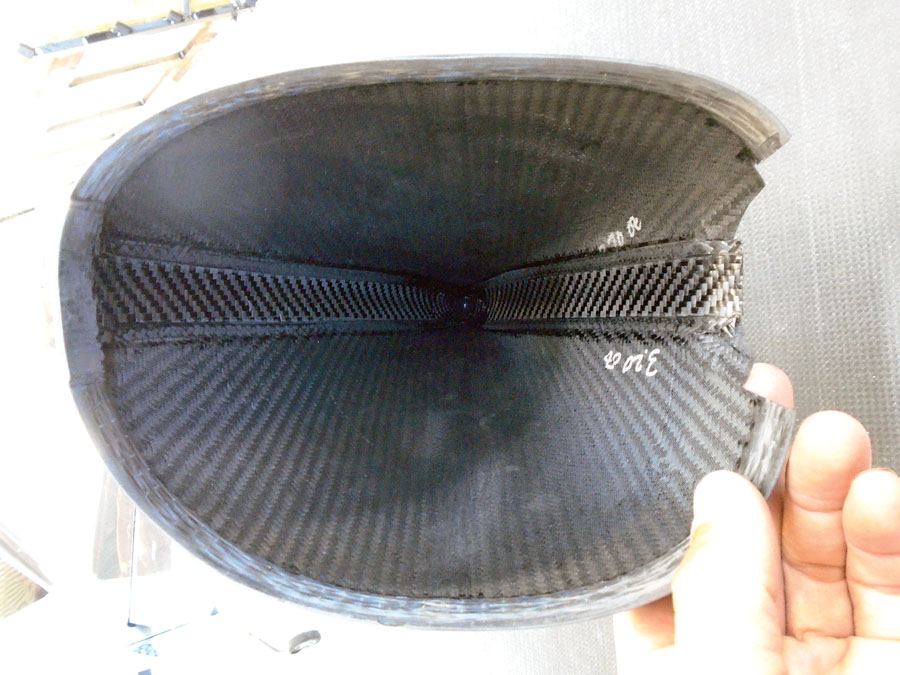
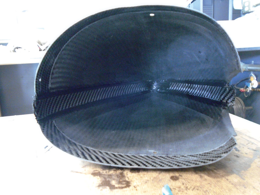
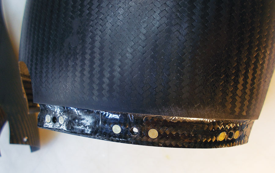
The interior join line is BID taped, as is the forward edge hoop strip.

Close-up of the uni hoop strip, which adds pant stiffness and allows for countersinking the join screws.
2. The edge flange is sanded flush with the top of the mold so that the mold half fay surfaces have no gaps. Place the pant in the mold and tape in place. Apply gel type CA (superglue) to the flange every 2 inches or so (the halves will be separated again after Cleco holes are drilled), and drop the top mold onto the bottom mold and glue the pant halves together. Take care not to glue the mold halves themselves together.
3. Remove the top mold. With the pant in place in the mold, drill Cleco holes about every 4 inches through the flange and into the mold. Move the pant assembly to the other mold half and match drill holes to the other mold.

A mixture of epoxy and flox/micro can be injected into the aft end of the wheel pant.
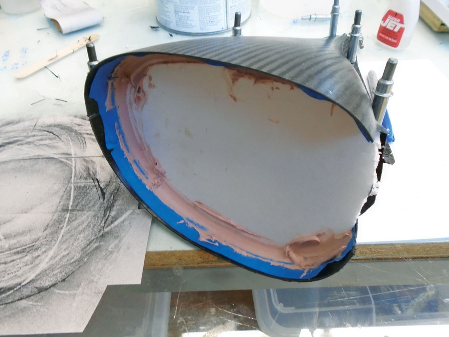
Apply protective tape inside the rear pant and cut cardboard or foam board to fit as a temporary bulkhead. Place the pant in the mold and bond the bulkhead in place with Bondo.
4. Cut the pant in half fore/aft at the join line with a Dremel tool.
5. Separate the rear pant halves to prepare for joining. Prep (sand, and mask as desired) the interior left/right join line for internal BID tape bonding (BID tape is bidirectional fabric oriented 45 degrees to the long axis of taping). Also prep the forward front/aft join edge for additional reinforcement approximately 1 inch wide. This is where the fore/aft halves are screwed together. The additional reinforcement strengthens the pant hoop-wise and provides material for countersinking flathead machine screws.
Sand the rear pant join edge planar. I use a glass table with adhesive sandpaper stuck to it.
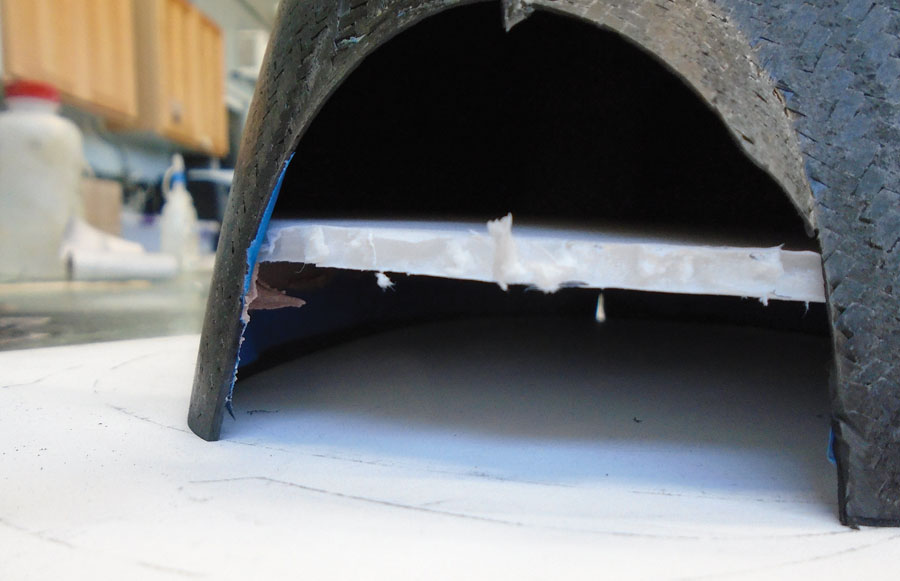
Check for flatness by sanding until no light comes in under the edge, then remove the temporary bulkhead.

Front pant halves Clecoed together for interior BID tape application.
6. Apply BID tape to the inside joint of the aft left and right pant halves. Use two or three layers of 1- to 2-inch-wide strips of BID. When the BID has cured, add 1-inch strips of 6- to 9-ounce unidirectional carbon to the forward edge. The uni can be added to each half separately (easier) or as a single hoop strip. The order of operations of this step can be reversed if desired. Use a syringe to inject a filler of epoxy/flox/micro at the trailing edge if it is too narrow for placement of BID.
7. Apply protective tape inside the rear pant and cut cardboard or foam board to fit as a temporary bulkhead. Place the pant in the mold and bond the bulkhead in place with Bondo. This stabilizes the pant for the next step.
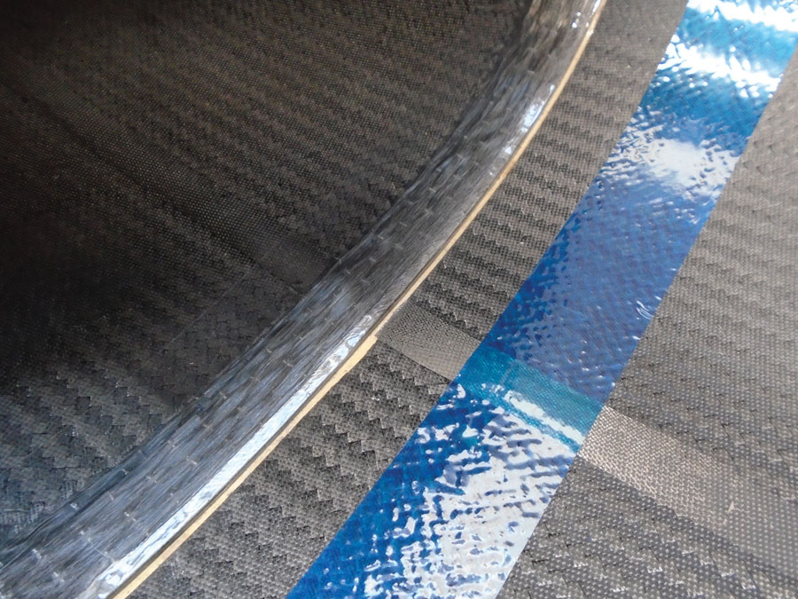
Front and rear pant halves placed in mold. Rear half has been sanded planar at the hoop strip. Front pant does not need to be sanded—the gap between the two halves will be filled flush with a strip of carbon tow. Although difficult to see in the photo, the hoop strip is covered with clear tape so that the nut plate flange will release after cure.
Apply BID for the nut plate flange using transfer plastic.
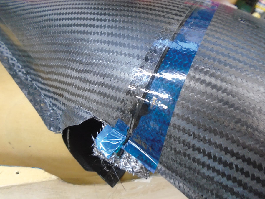
Be sure to apply release tape to the mold and the outer pant halves at the join line to avoid bonding the pants to the mold and to each other. In this photo you can clearly see the carbon tow used to fill the gap at the join line.
8. Sand the rear pant join edge planar. For this step, I use a glass table with adhesive sandpaper stuck to it. Check for flatness; sand until no light comes in under the edge, then remove the temporary bulkhead.
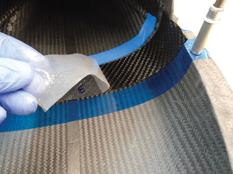
9. Separate the front pant left/right halves for the next step of making the nut plate flange. Cleco the right rear assembly and front right half into the right pant mold. This flange is laid up from three strips of 2-inch-wide BID tape. One inch extends aft over the front reinforced edge of the rear pant, and 1 inch extends forward to bond to the rear edge of the front pant. The rear pant must be taped about 2 inches back from the join line with flash tape so that the nut plate flange will release after cure. You also need to tape the mold itself about 2 inches either side of the join line so any epoxy that seeps between the pant halves in this step doesn’t bond the pants to the mold. Note that depending on how much you sanded in Step 8, you’ll have a gap of 0.1 to 0.2 inch between the front and rear pant halves. This gap should be filled with a strip of wetted 24K carbon tow before laying down the nut plate flange BID. Press the tow down into the gap to ensure a nice square edge against the rear pant when demolded. When the right half flange has cured, move parts to the left mold and repeat Step 9 for the left flange.
Untrimmed interior BID tape.

Flange trimmed with Dremel in order to apply outer BID tape.
10. Trim the nut plate flange as necessary so that the front halves will fit together, but do not final sand just yet. Sand the inside bond line to prep for BID tape.
11. Bond the front halves together with CA along the flange. Use the holes drilled in Step 3 to ensure proper alignment of the halves. Again, take care not to bond the pant to the mold.
12. Apply BID tape to the interior join line of the front halves, the same as Step 6. When cured, trim the outer flange and apply BID tape to the exterior join line of both the fore and aft pant half as desired. Exterior BID taping is optional but recommended.
13. Follow with planar sanding of the forward pant half nut plate flange, the same as Step 8.

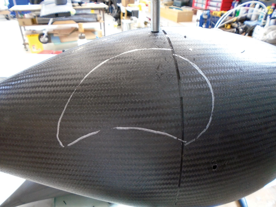
For initial fitting, a pair of sacrificial pants was made. These helped establish initial trim lines on the actual pants.
The carbon tow used to fill the gap created by cutting the front and rear halves apart is clearly visible in this picture. Trim lines are marked with silver Sharpie.
14. Fit the pants to the wheel. For the time being, drill 3/32-inch holes at the locations where you will screw the pants together, but do not install nut plates. You will be assembling/disassembling the front and rear halves numerous times during fitting, and this is much easier done with Clecoes rather than screws.
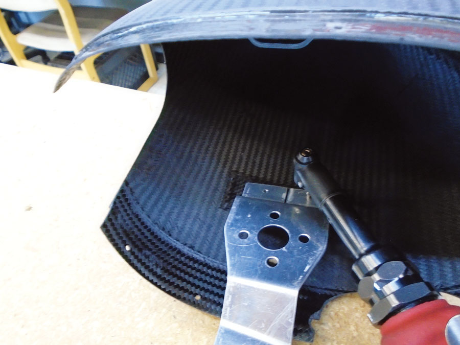
15. A standoff bracket that screws to the end of the axle positions the pant left/right and up/down as viewed from the front of the pant. This is where having the axle centerline molded into the pant is helpful as the bracket screw hole will be concentric with this centerline.
16. The inner side of the pant will attach to a bracket that piggybacks on the wheel/brake mounting hardware. Give consideration to maintenance issues for this bracket, i.e., you might not want to have to jack up the plane to take off a wheel in order to take off a wheel pant bracket (although the only reason you’d probably want to remove a pant bracket is if it got banged up somehow, in which case you’ll probably be removing the wheel anyway).
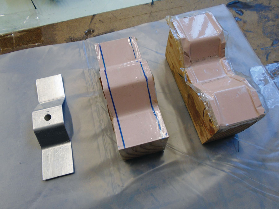
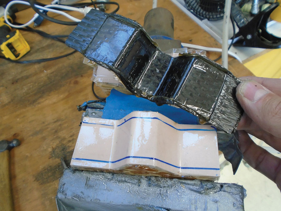
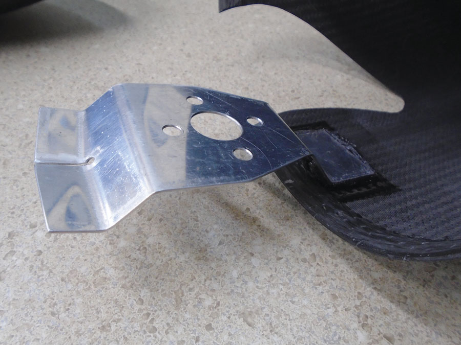
The standoff bracket is initially fabricated from aluminum for trial fitting. This allows easy bending of the bracket to establish a good fit between the pant and axle.
Once the bracket is the correct shape, a Bondo splash mold of the bracket is made and a carbon standoff is fabricated.
The standoff bracket is screwed to the axle. A mix of epoxy and Cab-O-Sil is applied to the bracket feet and the pant assembled to the wheel, bonding the bracket in place.
17. Using lasers and plumb bobs is helpful, assuming you have an orthogonal reference—this works best when the gear can be mounted on a worktable. Consider including datum lines for reference in the mold scribe lines. These can be easily filled in later when prepping the pant for paint.
18. Once the inner bracket has been fabricated, laminate a one- or two-ply carbon doubler patch for extra strength where the bracket attaches to the pant.
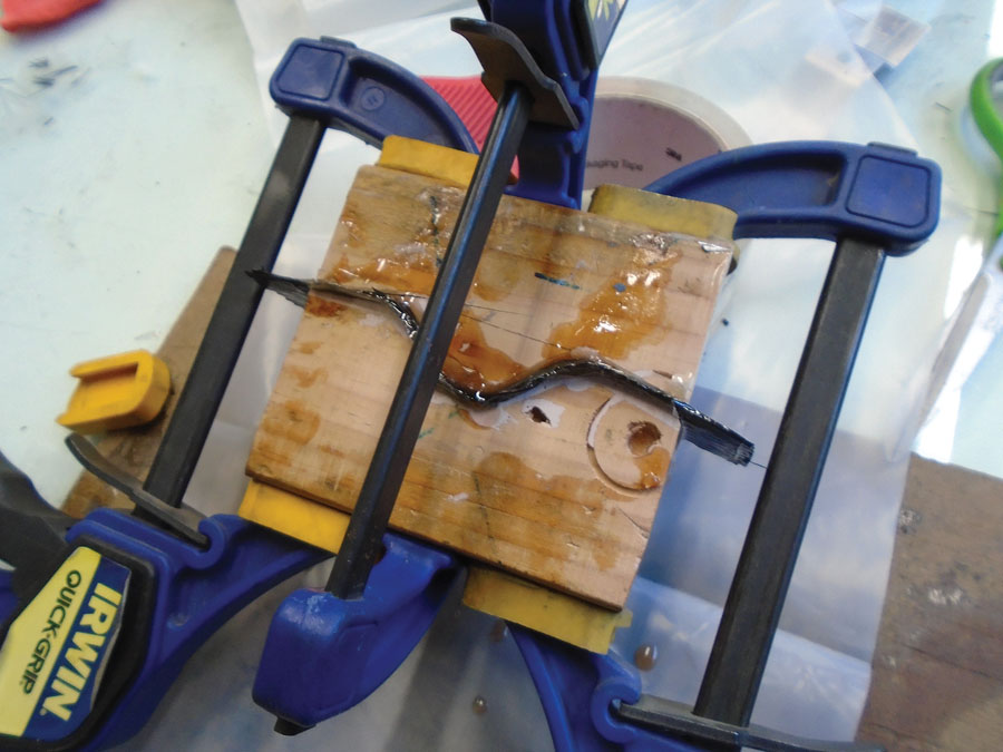
19. Make a shim between the bracket and pant so that the pant fits perfectly against the bracket. First put a release on the bracket such as packaging tape, Frekote (Loctite) 770NC, or wax plus PVA. Then mix an epoxy shim (epoxy mixed with Cab-O-Sil to the consistency of petroleum jelly to avoid sagging while the shim cures) and apply to both the bracket and doubler.
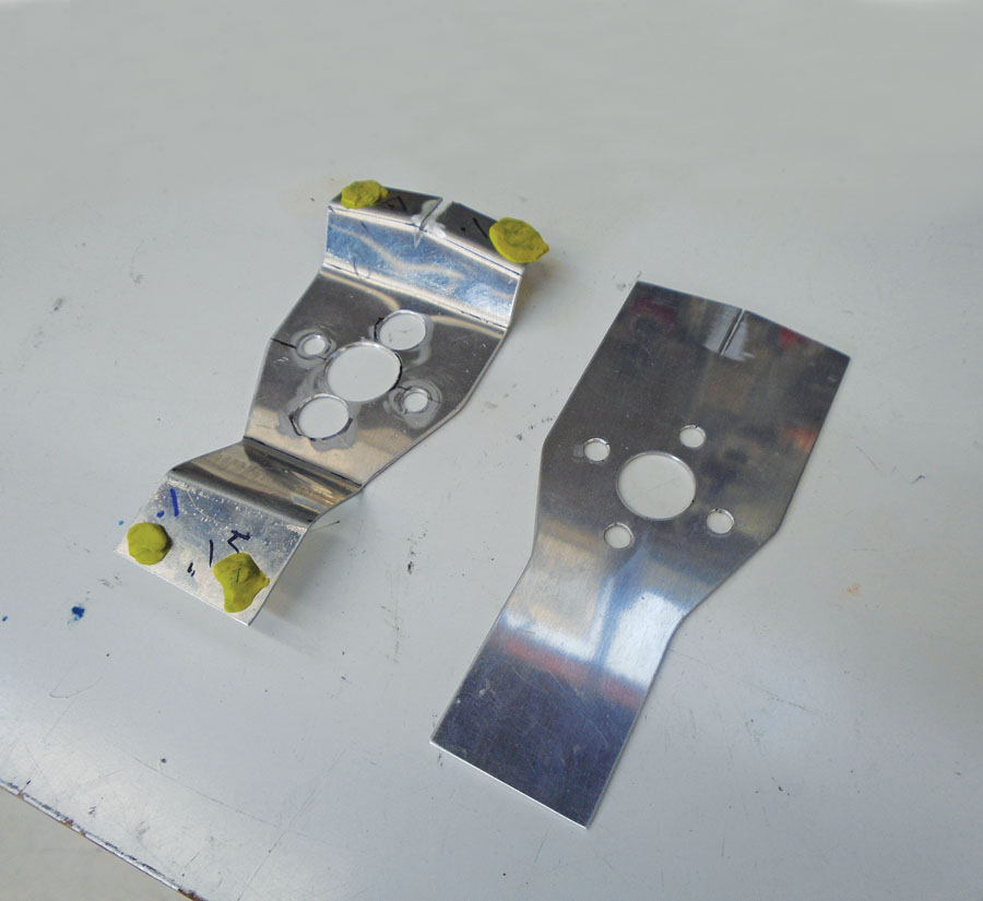
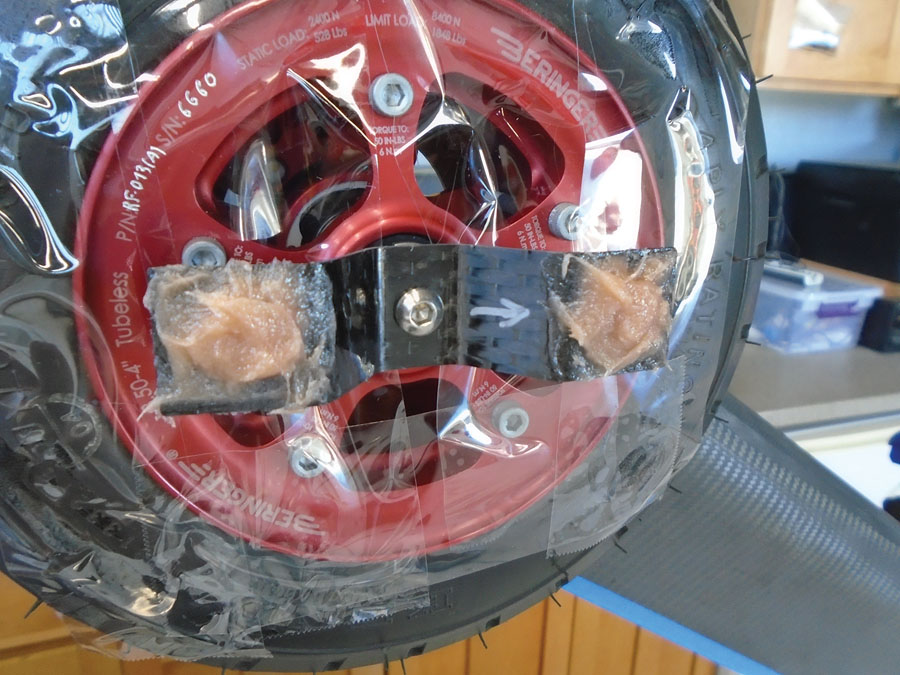
As with the standoff bracket, a trial bracket is first fabbed for fitting purposes. Here the proper bend angles have been established. The yellow blobs are Play-Doh “depth gauges.” This allows the pant to be fit and the proper shim depth to be determined. Note: Whenever using Play-Doh, clay, etc. for gap measurements, be sure to put tape wherever the Play-Doh will touch to avoid contamination.

Machining the mounting holes in the final part. One trick for machining sheet metal is to glue it with contact cement to a sacrificial plate (here, MDF) that can be clamped in the vise.
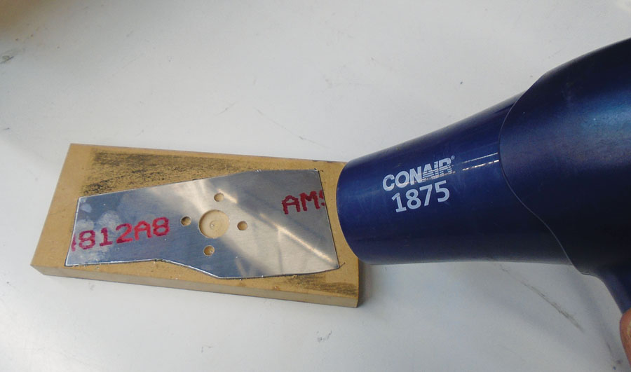
The part is easily removed from the MDF by applying heat for a few seconds, which softens up the adhesive enough to shear off (do not pry) the aluminum without bending it.

To make a shim between the bracket and pant, first put a release on the bracket using packaging tape, then mix epoxy with Cab-O-Sil and apply it to both the bracket and doubler.
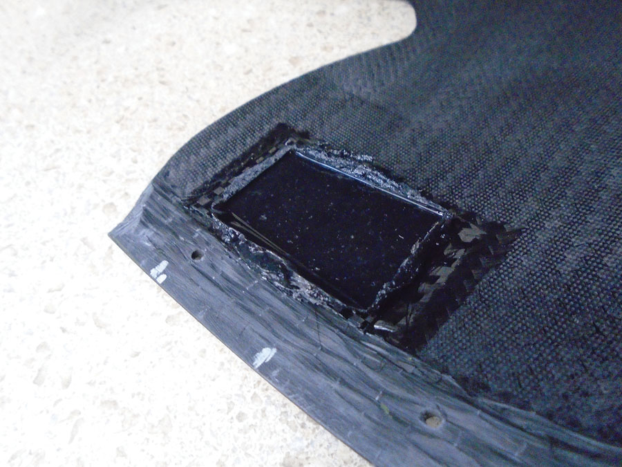
The cured shim, co-located over the carbon doubler patch.
Once the shim has cured, mate the bracket to the shim.
Back drill through the bracket and pant for the attach screws.

Rivet nut plates to the bracket.
20. Once the shim has cured, mate the bracket to the shim and back drill through the bracket and pant for the attach screws. Then rivet nut plates to the bracket.
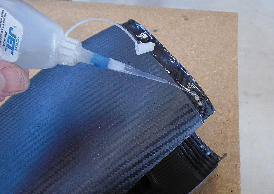
21. Assemble the pant and enlarge the 3/32-inch holes to final size. Install nut plates on the nut plate flange. Screw countersinking can be done with a regular micro-stop countersink; 220-grit adhesive sandpaper stuck to a zero-degree deburring tool also works well. Nut plate holes and rivet/countersink holes (or other holes in carbon) should be dabbed with penetrating superglue. Thin (blue bottle) Jet CA with a #303 extender tip from CST Composites works well. This seals the carbon/metal interface to prevent galvanic corrosion and also makes sanding any fuzzy edges easier.
22. Apply a slurry of epoxy/micro to smooth out any irregularities in the tape joint or other surface imperfections. Add carbon black to the mix if you want the slurry black.
Assemble the pant and enlarge the 3/32-inch holes to final size. Install nut plates on the nut plate flange.

Nut plate holes and rivet/countersink holes (or other holes in carbon) should be dabbed with penetrating superglue.
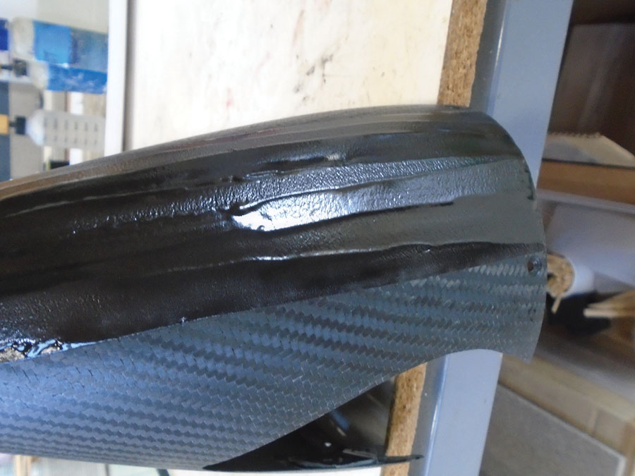
Apply a slurry of epoxy/micro to smooth out any irregularities in the tape joint or other surface imperfections.
Add carbon black to the mix if you want the slurry black.
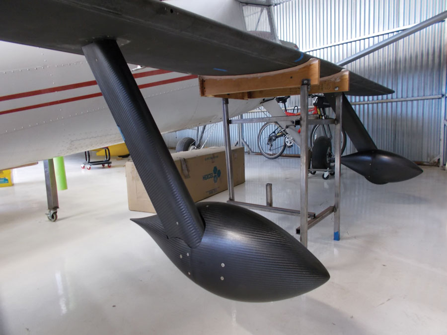
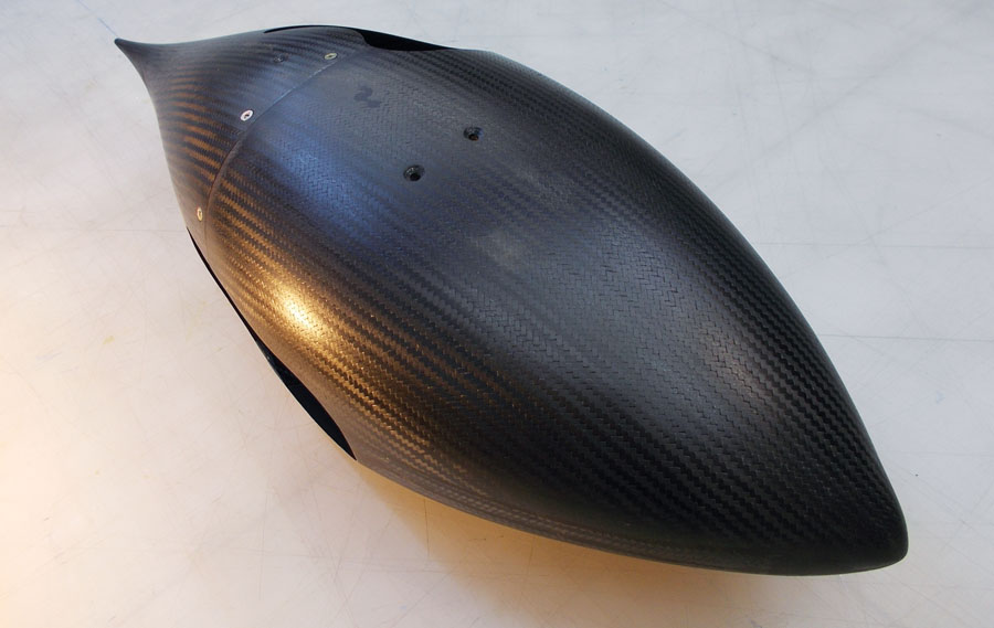
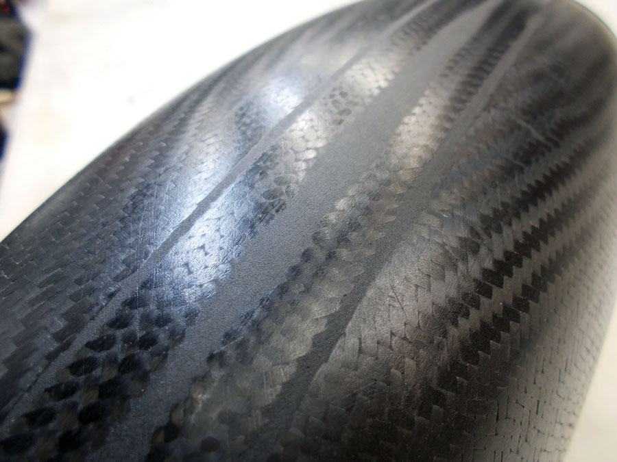
The finished pant. A lot of work, but necessary if you want custom pants.
That’s it for DIY wheel pants. They are a lot of work to get light and straight, but a fun and not too difficult project to tackle if you have the time!
For further reading on Galvao’s method of transforming 2D foils into 3D bodies of revolution, see “A Note on Low Drag Bodies” on the CAFE Foundation website. For more on optimal thickness ratios for streamlined bodies of revolution, see Bruce H. Carmichael’s book, Personal Aircraft Drag Reduction.


Would like to know about the decalage of an aircraft (may not have spelled that right)
Or the AOA of the horizontal stabilizer in relation to the wing AOA , and how it would effect trim
There was a Kitplanes article covering the subject way back in 2003 to 2005 I think.