When we finally came to the noisy end of the airplane, we had some decisions to make. The Bearhawk LSA is designed around a small four-cylinder Continental engine, although there are builds in the works using a Lycoming O-235 and a Corvair conversion. Philip Groelz had done quite a lot of work on a rotary (Wankel) engine, and we could have assembled one of those if we chose. I’d flown the Rotax 912 quite a bit in RV-12s, including three trips over the Rocky Mountains. It’s a lovely little engine, and I’d take it anywhere.
We spent a lot of time imagining where cooling air had to go and building a set of baffles to make it happen.
We considered all these possibilities. I had a particularly hard time turning loose of the Rotax and its advantages: substantial weight savings, better fuel economy, modern ignition and monitoring systems. However, a new one was financially impossible, affordable used units are difficult to find, and engineering a successful Rotax installation, particularly the cooling system, is not a trivial task—I’d watched the engineering staff at Van’s spend a lot of time and energy on the RV-12 installation. They were (and are) very smart, and they were getting a salary to do it, neither of which applied to me!
We decided that the point of our project was a flying airplane, not engine/engine installation development. With thousands of airplanes, including several local ones we could look at, using four-cylinder Continentals, we decided to stay in the mainstream.
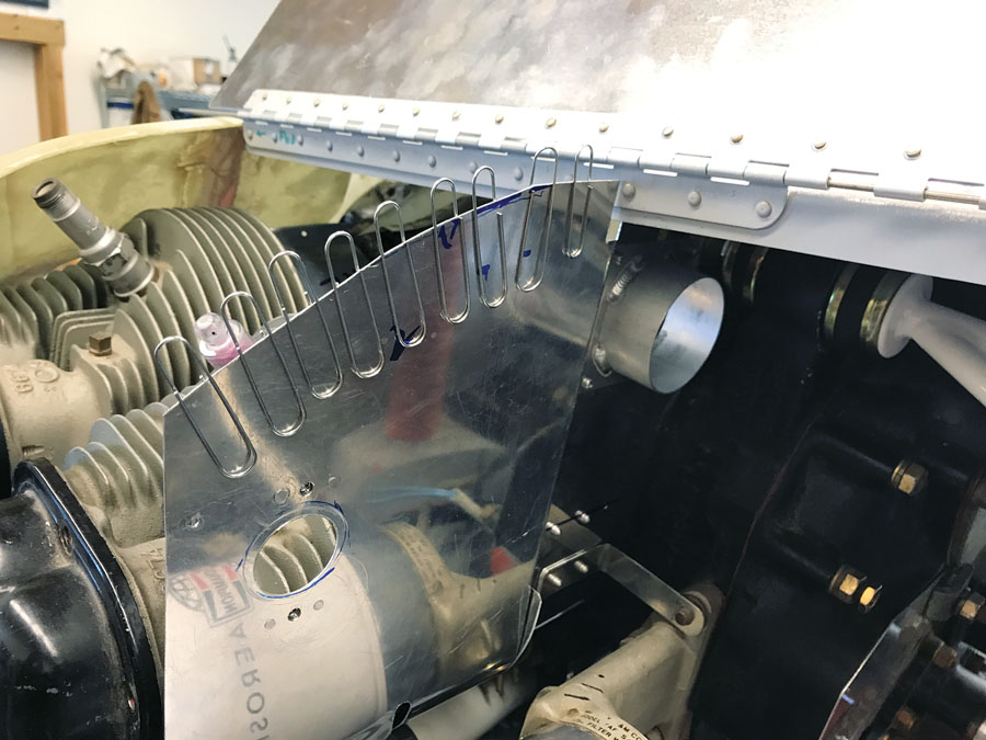
Paper clips helped measure the space between the baffles and the cowl door.
After some local and internet shopping, we located an O-200B in Southern California. It had started life just a few miles from our project, powering, of all things, a blimp. It still had several hundred hours until TBO. The B model is relatively rare (the O-200A is much more plentiful) and usually used in a pusher configuration—as it was in the blimp. We had a difficult time determining whether or not it was suitable for our tractor airplane. Finally I went down to the Continental booth at Oshkosh and put the question directly to the source. We were assured that while the A model was strictly a tractor engine, the B model would work in either configuration.
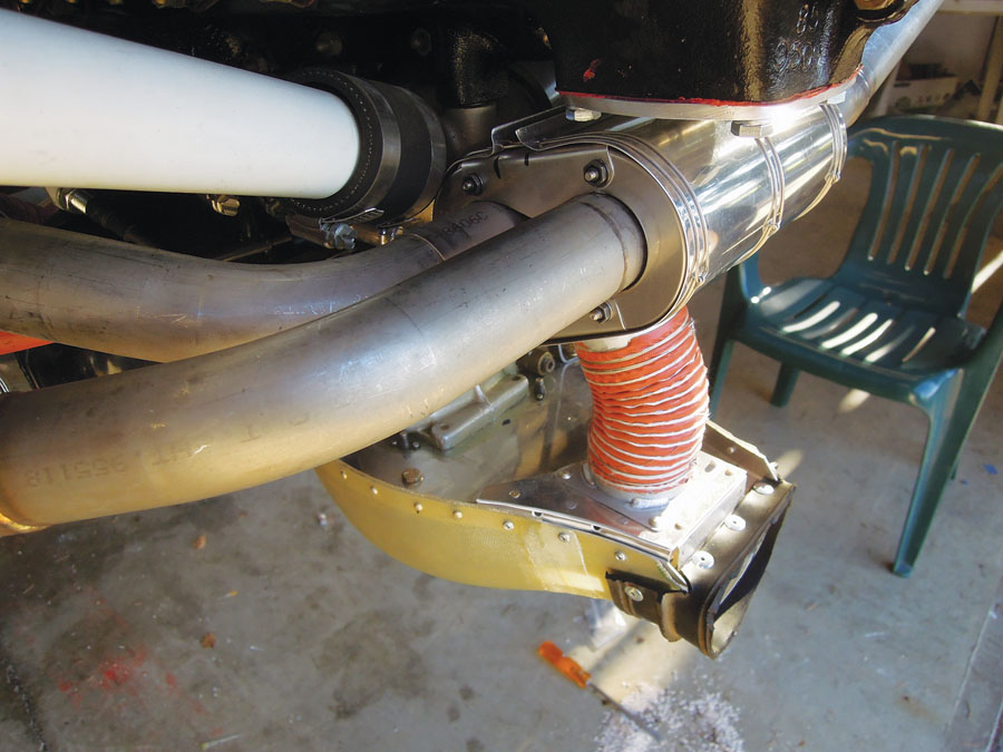
We made the deal, and a couple weeks later a heavy crate arrived. We pulled the engine out of the box with an engine hoist, drained all the oil (I won’t make that mistake again!), pulled the oil tank, and had a look around. The logs showed almost no time since an extensive overhaul, and there was no visible internal corrosion. Master mechanic Larry Beck came over and peered and poked around the cylinders and bottom end. He pronounced it sound, at least as far as could be determined without taking it all apart. We decided that we’d fly the engine as it was, but we did buy a B&C alternator and a Vetterman exhaust system. Neither was cheap, but they were both beautifully made and significantly lighter. We dithered about the stock, heavy starter, but eventually decided to save some money and keep it.
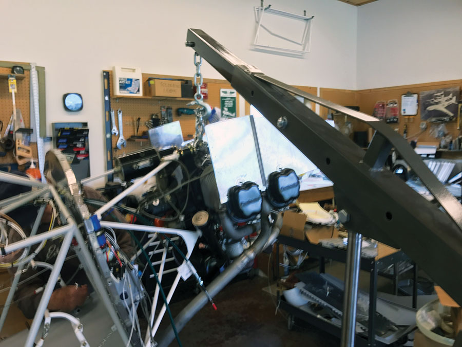
Hanging the engine and roughed-out baffles.
Engine Mount and Baffles
The actual construction plans don’t even mention an engine mount, but we found some basic directions in the small booklet that came with them. That booklet must have been printed on a worn out copier from the ’70s—the photos are almost useless—but there was enough information to build a mount. The distance from the wing leading edge to the crankshaft flange is given as 59 inches. We built a stand that located the engine and aligned it with the leveled fuselage. With the offset fin, evidently no thrust-line offset is necessary, so some chalk lines on the floor and a plumb bob on the crank flange sufficed for alignment. With steel bushings and washers on the engine and the firewall, we cut and coped tubing to connect the dots, following a line sketch in the booklet. The -inch x .058-inch tubing specified seemed pretty “whippy,” but we’ve learned a few lessons about “improving” on the design and went ahead with it. When we had the mount welded up, I bolted the engine vertically to an engine stand and began making patterns for baffling. I’d done this several times on Lycoming engines, and given that experience, I thought this task would go quite quickly.
Oh, so wrong.
We had to modify the Van’s airbox to fit the Continental oil tank.
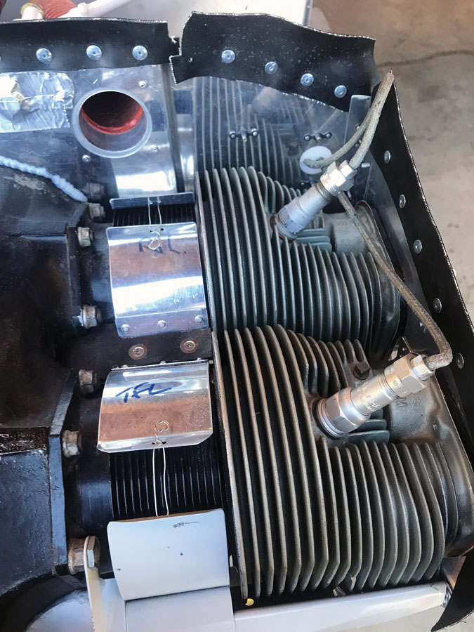
Unlike the Lycoming, which has a number of tapped bosses specifically for baffles, the designers of the Continental seem to have never considered the matter. There are few places on the case where brackets can attach, but on the cylinders only the screws holding the rocker covers are available—which means that the baffling has to be cut to fit the curves and dips of these pressed sheet metal parts. I made a particleboard template that I could use as a router guide—it sort of worked. Lycomings almost always come with the important inter-cylinder baffles, but I couldn’t find any available for the Continental, so I had to make my own. By the time I’d finally completed a rough set of baffles and fitted them to the engine, I’d spent probably 60 hours of patternmaking, cutting, fitting, filing, bending, and riveting. Some of it was actually spent on useable parts…
There was even more work when we built the cowling and had to trim the baffles to fit it, then install the air seal material. Philip and I worked together to make the baffles fit as tightly as possible to the case and cylinders. By that time I’d had enough of baffles, so Philip took over and devised a seal around the crankshaft and patiently worked the air seal material into the tight shapes necessary to seal around the air intakes in the nose bowl. Quite a few more hours went into that. By the time we were finally done, we had the tightest baffles any of us had ever seen on an O-200. Will it cool properly? We shall see.
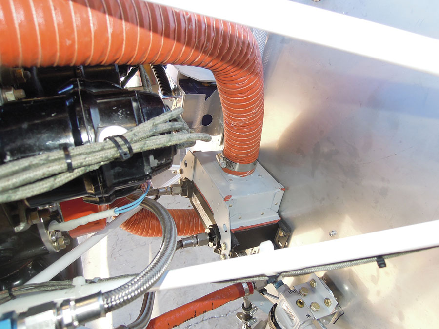
Carb heat is important on an O-200, so our box uses both crossover pipes.
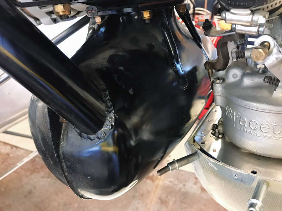
Speaking of cooling, initial reports from Bearhawk LSA builders suggested that an oil cooler would be desirable. I’d had good luck with a small Setrab unit on my RV-6, and it was much smaller, lighter, and cheaper than traditional aircraft coolers. We mounted a Setrab on the firewall and ran a duct off the rear baffle for the cooling air. An adapter sold for race cars was mounted underneath the oil filter and provided the outlet and inlet for oil hoses.
Doing It the Hard Way
We ordered a nose bowl and spinner from Bearhawk. If we’d used the stock Cub-style airbox, the nose bowl would have needed no modification, but of course, we had something better. The Van’s airbox uses a circular air filter mounted in a fiberglass “bedpan.” In the Lycoming installation it is designed for, it provides excellent pressure recovery and filters heated/alternate air before it reaches the carburetor—something the Cub-style box doesn’t do. Nobody we’d heard of had adapted Van’s unit to a Continental, but given its apparent advantages, we decided to give it a try. As usual, it turned into more work than we expected. The rear of the bedpan had to be altered to fit the Continental oil tank, and an inlet added to the nose bowl to fit around the intake of the airbox. We eventually made it all work (fiberglass is such a miserable material!). Carb heat is much more important on Continentals than Lycomings, so Philip designed and built a lovely carb-heat muff, using some parts from a standard heat muff and some parts he designed himself. The result surrounds both crossover pipes and has a short duct to the airbox—it should give plenty of heat.
A small Setrab oil cooler should help in the summer.
We had to build steel brackets to provide cable stops for the throttle, mixture, and carb heat cables. Several iterations were made and discarded before we had something that made us happy. Later we learned that Bearhawk had a retrofit oil tank that was not only lighter, but had cable stops built in. Sigh.
The mag harnesses were worn, but not damaged. The mags themselves had almost no time since a 500-hour rebuild 15 years ago. We didn’t know if all that sitting had harmed them, but we decided to at least start with them and rebuild/replace them if necessary.
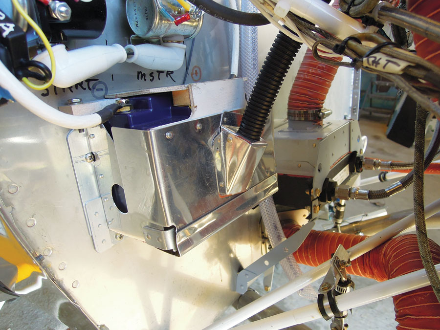
We built a stainless box with a blast tube for the EarthX battery.
In the end, we had a tightly baffled O-200 with a new alternator, new exhaust, new baffles, new plugs, and new oil cooler. We retained, unaltered, the mags, harnesses, starter, carburetor, and basic engine assemblies. We saved some money by making many parts from scratch, but if we’d used things like the stock airbox and Bearhawk oil tank, we could have saved a lot of time.
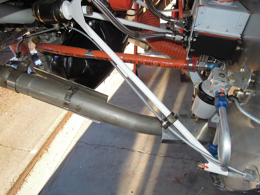
Vetterman exhausts and an Andair gascolator—both high-quality products.
Finding a Prop
The point of the engine, of course, is to spin a prop. There’s no such thing as a “standard” prop for this airplane, but there are several possibilities. Bob Barrows is flying with a carbon fiber prop he built himself, patterned after a metal McCauley that had given good performance. Several metal props from airplanes like Ercoupes and Aeroncas might work, and Philip had a couple of these. And there was a wide selection of props from custom prop makers—Mark Goldberg has a Catto two-blade on his LSA that gives better performance than anything else he’s tried.
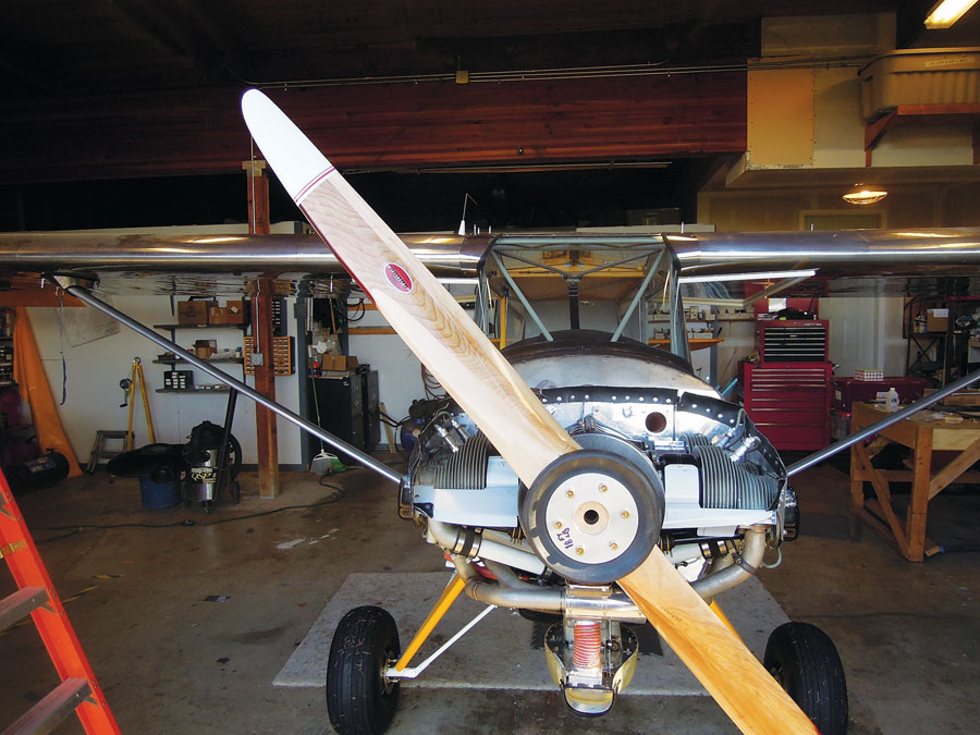
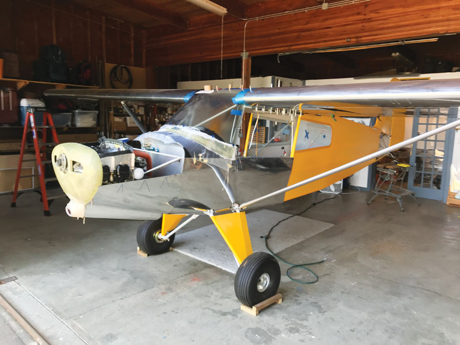
The Bearhawk landing gear provides plenty of room for a 76-inch prop.
I’ve had the chance to peek over the shoulders of engineers and prop manufacturer reps and see the results of highly instrumented, professionally run tests of various prop/engine combinations. The unpredictability of the results, many directly opposed to conventional wisdom, impressed me deeply. I wasn’t willing to fly behind anybody’s homemade composite propeller—call me a chicken if you like. A metal prop had some advantages—including making the engine easier to hand-prop if we decided to eliminate the starter—but came with the uncertainty of unknown resonances and a significant weight penalty. We’d worked hard to bring this airplane in light, so we ended up having a new 76×44 wood prop built by Props, Inc. in nearby Newport, Oregon. It was done in three weeks, weighed (installed) at least 15 pounds less than a metal prop, and cost 60% less than fancier wood or wood/composite props.

Philip Groelz (left) and Larry Beck set the timing.
The folks at Saber Manufacturing shipped us a set of prop bolts and a crush plate the day after we placed our order, and we hurried out to put our shiny go-stick on the front of our airplane.
We can’t wait to see it convert fuel into thrust!


I have been very entertained watching videos by Trent Palmer & Mike Patey which has left me considering what my dream build would be. The Bearhawk Patrol caught my attention & listening to Bob Barrows design principals I am sold.
Watching MojoGrip videos talking about his Rotax 915 iS performance at altitude from the turbo and the automation of the constant speed prop setup, and Trent talking about being able to run Mogas, I really like that powerplant, but it didn’t seem ideal for the Patrol.
I am currently looking for rules on LSA Utility, (Part 23?), hoping to find a quick answer if the Rotax 915 iS would be legit for the Bearhawk LSA, but I see navigating FAA Rules isn’t streamlined to say the least. Going to reach out to Bearhawk.