KITPLANES Magazine, April 1997
Building a RotorWay 162F
Part 2 of 8: Unpacking
by Jeff Dunham
Last issue we looked at RotorWay International and its history, and we studied the actual 162F helicopter kit itself. This time we’ll discuss builder requirements and time to completion; we’ll talk about construction plans, procedures and tools. And finally we’ll examine and assemble the first two major steps in our kit: the airframe and the main shaft/rotor hub.
Making It Feasible
An obvious RotorWay goal for customers has always been ease of construction of a very complex machine. Because helicopters in particular are truly the sum of their parts, the most complicated and critical components within RotorWay kits are preassembled at the factory.
These items include the engine, the elastomeric rotor hub, the tailboom, and the secondary drive unit. (We’ll look at each of these pieces in more depth throughout this series.) But when it comes to “easy” construction, it hasn’t always been this way for RotorWay builders.
Each generation of RW kits has been more finished by the factory, and step by step from the Exec 90, through the Exec 90 Quick Kit, and now onto the 162F and all its improvements, RotorWay International currently has a palatable and appealing package for even inexperienced builders. Along with a fully welded airframe, all steel subassemblies and components are now assembled and prewelded by the factory, so there is almost no welding required of the builder.
The tailboom is built and ready to be bolted on the frame, and a fully strung wiring harness with all switches and connectors crimped, soldered and finished off with heat shrink tubing is ready to be laid in the ship and hooked to the various systems and components.
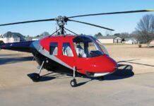
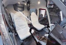
Also, the 162F’s body is more sleek, and a Cabin Comfort Package has been added that forces heated or cooled air into the cabin. The engine and all systems are monitored and controlled by the new FADEC system (fully automated digital electronic control).
In addition, a second-version software package has recently been implemented in the FADEC system that will give the pilot specific engine parameters, pre-, post- and during flight. According to RotorWay, this setup makes the 162F one of the most advanced piston helicopters on the market today, either experimental or certificated. We’ll of course cover all the fancy details of this operating system within the next few articles.
How Many Hours?
After listing all these glowing accolades, we now come to the ever dubious questions: “How long is it really going to take me to build this flying marvel, and what kind of tools do I have to use to do it?”
As for building time, read a review of any kit aircraft. If the author didn’t assemble the plane himself, he usually quotes required building time hours from factory propaganda. You should then add a grain of salt and multiply by two…or three! It’s almost a given that you’re going to spend more time building a kit aircraft than you expected when you began. The ads aren’t meant to be misleading… just… “encouraging.”
RotorWay claims the average builder can complete the 162F task in 350 hours. Are they being a little too “encouraging”? And what the heck is the “average” builder? Is this the A&P mechanic who used to rebuild Hueys or is it his next door neighbor, the accountant, who has a Swiss Army knife in a drawer somewhere?
If you’re familiar with hand tools and can do the basics like drilling holes with a drill press, cutting metal on a band saw, and properly torquing bolts without stripping them, and if you add only a couple of non-kit items like a radio and transponder, yes, you can finish in 350-400 hours of actual physical labor and without much detail work.
But keep in mind that a lot of time can be accumulated through hours of staring at tools and materials and plans as you wonder if you’re about to screw something up. Granted, the current kit has been greatly improved and simplified, but things go a lot slower when you’re standing there scratching your head, or if you think a feeler gauge is something used by a doctor.
A lot of RW builders are claiming 500-550 hours of building time, but that includes good detailing, and conversely I’ve heard of folks spending as much as 3000 hours.
RotorWay claims most customers are finishing in about a year, working evenings and some weekends. This might seem quick for such a big project, but a big time-saver is the minimum of fiberglass and gooey work done by the builder. There are of course areas of actual fabrication, but this kit is closer to “bolt-together” than most homebuilts. Comparatively, for those who have built a standard Lancair kit or the like, this thing is going to be a quick walk in the park.
I think the main reason that builders are finishing the 162F so quickly is a leap forward in RotorWay’s construction documentation: construction videos!
Even though this is my third RotorWay helicopter project, these six new tapes have been a huge help in showing and reminding me how to go about certain tasks in the construction process. They say a picture is worth a thousand words, but these videos are priceless. They truly give you confidence in the building process; they make what you’re doing completely clear.
I think I will finish my ship in about 400 hours. For comparison, fellow builder Mike Sherick says his came in at about 1200 hours, but this was his first RotorWay project, his ship is magnificently detailed, and he added a good number of extras, some of which we’ll cover in these articles. Your hourage may vary!
Tooling Up
As for tools needed to complete this project, you’ll want the standard implements used for minor twiddling on cars, plus a few larger tools and a handful of oddities that we’ll list.
As for the big expensive tools, you’ll need a drill press, a metal-cutting band saw, bench grinder, hand grinder with additional metal cutting wheels, a small floor jack (for lifting the engine into place), and of course a shop vac. (Sanding jell coat is a mess!) An oxygen/acetylene gas welding setup is not absolutely essential since 99% of all welding has already been done. The only places you’ll need to weld are on the two door latches (if you even plan on using the doors!) and on the end cap of the ballast weight. We’ll explain about the ballast weight when we get to it! Also, don’t make it a habit, but if you misdrill a hole, it’s nice to be able to weld it shut and try again.
As for the smaller stuff, besides the various standard wrenches, sockets, screw drivers, hammers and such–typical of any home shop–you’ll need these items, and I don’t think I left much out!:
A pop rivet gun, a heat gun, tap and die set, bearing puller, caulk gun with silicone sealant, a good spray paint setup, a few large wood clamps and a few various sizes of standard clamps, dial caliper, dial indicator with a magnetic mount, protractor level, two or three good bubble levels, extendable magnet pick-up (very handy), small extendable mirror (also very handy!), metal files, Allen wrench set, 4-foot straightedge, lots of various cable ties, a top-of-the-line torque wrench capable of measuring inch-pounds (critical), a fish scale (for measuring belt tension), small bearing puller, a rotary or Dremel tool with its various bits, left and right aviation tin snips, and the typical things for electrical wiring such as a soldering iron, solder and a multimeter. For body fitting, Clecos and Cleco pliers are supplied in the kit.
I have to admit that waiting for a RotorWay helicopter kit to arrive at your house is about like being nine years old and waiting for Christmas. Once you get past the initial shock of wiring $60,000+ to RotorWay’s bank account, you begin to anticipate how much fun this thing is going to be.
The future helicopter arrives in eight boxes and crates of various weights and sizes, so you’ll need considerable space to store what you’re not working on, not to mention what you’ll need to build the thing.
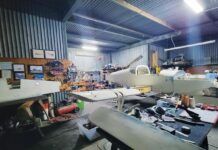
Obviously if you have a hangar or an empty three-car garage, you’ll have no trouble. I built my first one in a three-sided barn in Texas and the second one in a hangar in San Diego. But this third kit has been the most challenging: After putting the frame together in the hangar, I moved it home to my three-car garage that was already full of other stuff. So now with all the tools, boxes, and the building area, it’s a tight fit!
If you have the space and the patience, you’ll want to do a complete inventory of the kit once you receive it, mainly to become familiar with parts, but also to see if anything’s missing. From what I’ve found, that almost never happens unless something is backordered, which is also a rarity. RotorWay also requires that you must claim missing parts within two weeks of receiving the shipment. But I’ll say it again: You almost never hear of something missing from a RotorWay kit.
Also, try to keep all the components and parts cards in sight and right at hand. If you have enough empty wall space, hang the parts cards within easy reach so you’re able to see and go to each piece immediately. This is a good way to keep track of everything, and it saves a great deal of hunting time.
The kit goes together a few parts cards at a time and is well laid out, but it’s nice to be familiar with and to glance at all the parts while you’re working.
If you build in your garage, keep in mind that with the main shaft mounted, you’ll need a bit more than 8 feet of ceiling height–more if you want to winch the main shaft up when it needs to be raised. And a few times during construction, you will have to raise the shaft straight up about 10 inches, sliding it up and down in the bearings. If you use a winch, it’s much easier. The alternative is just raising it by hand and temporarily locking it up with a quick turn of the lock ring: a good way to build muscle!
If you build the ship in a garage, you’ll also have to think about getting the helicopter out once it’s finished. Most garage doors are much lower than the 162F’s main shaft. Hmmm…. Stretch and Tom at RotorWay both told me that after assembly, you can loosen the rear landing gear, rotate it backward, dipping the rear end down, and thus putting the ship into a pretty good wheelie position. You can then slide the whole ship outside that way.
We’ll see. This is what I will have to do. With this setup, the tailboom can’t be attached, and even though the boom is one of the first parts in the kit to be assembled and mounted to the frame, you can either remove it to exit the garage (eight bolts, one belt and one cable) or don’t even bother mounting it to the frame until you get the ship to the place where you’ll be final rigging and test flying. It also helps not to have it mounted during the rest of construction because it just gets in the way and isn’t needed when installing other components.
This brings up another appealing aspect about the 162F kit: You can assemble it in stages, almost module-like. For example, if you get tired of working on the tailrotor, put it aside and work on the controls.
Many components and assemblies can be worked on simultaneously and independently of each other and only need to be married together in a certain order toward the end of construction.
More Building Details
The plans for the 162F consist of three loose leaf notebooks with hundreds of photos and simple step-by-step explanations of what to do next; a pile of about 20 construction drawings and blueprints; the six video tapes; and two more loose leaf notebook maintenance manuals, one for the overall ship, and the other for the engine.
Each chapter in the notebooks contains a major step in the construction process. Everything is in the manual in a logical order and you can build from start to finish in the order presented. But as I mentioned before, if you’re interested in jumping to something else later in the kit, (or you don’t want to mount that big long cumbersome tailboom yet), you can usually build the subassemblies and wait to final-install the items until another time.
Obviously you’ll want to consult with RotorWay when deviating from the plans any significant amount. Some items of course must be put in before others.
For the most part, I’ve found these new manuals to be thorough and easily understood. On a few occasions I’ve found myself studying something a little too long, which resulted in a quick call to RotorWay for clarification. Updates and revisions are made to the ship and/or plans rarely, but when appropriate, each builder is sent either a notice or a mandatory bulletin, or they’re simply sent updated manual pages to add to or replace existing ones.
For example, recently new air scoops were added to the ship. These scoops mount near the front of the tub on the bottom of the ship and effectively lower operating temperatures a few degrees. I received three additional pages for the manuals with an offer to purchase the new scoops. Sixty bucks and two days later the fiberglass pieces were sitting on my workbench ready to be installed.
Before starting any construction, I would highly recommend studying every step of construction and familiarizing yourself with the overall project.
Get an overview of the manuals and watch the tapes. One note: You will be overwhelmed with the apparent enormity of this project. Part names and numbers start to run together, and at first glance some of the procedures might be unclear. But do a quick overview of the videos, the plans and the drawings, and you’ll get a great sense of how everything actually goes together, and you’ll see the fun yet to come. And don’t burden yourself with trying to understand every step completely before you actually get to it in construction. It’s much easier when you’re holding each part, getting ready to work on it. Just think of building this machine as simply one small step at a time. It will soon be time to fly!
Finally, Building It
The first area of construction is the airframe. It’s made of 4130 chromalloy steel, with all welding having been done at the factory. It’s truly a piece of artwork. I can’t tell you how cool it is to drag the airframe out of the shipping crate, pull the unattached pieces apart, place them on the ground around where they will be attached to each other, and to already see the beginnings of your own helicopter. It’s quite amazing and most of your friends and relatives will think you’re nuts. But as the process continues, skeptics become fascinated and others are amazed that you are actually building a real helicopter.
The airframe comes fully welded but still as raw metal coated in a light grease to avoid corrosion. The builder must first temporarily assemble the frame that will include laying out the landing gear and struts to correct measurements, drilling two holes at each of the four steel shoes and through the skids, bolting this assembly together, mounting the main frame on top of the landing gear, then drilling four more holes and bolting these assemblies together. You’ll also pound four aluminum skid end caps into the skids and secure them with two rivets each. All quite simple.
The bolts holding the skids onto the landing gear are 1/4 inch and go through the steel shoes and the aluminum skids. There is a right skid and a left skid. The right skid, or passenger-side skid, has a steel pipe inside the front kick-up portion of the aluminum. For weight and balance, a 25-30 pound bullet-shape weight is transferred to either the front right skid in solo mode, or is mounted underneath the front of the tailboom behind the center of gravity when a passenger is riding. A 1/4-inch steel pin is used for holding it in place, and it can be moved to either location in a matter of seconds.
So it’s very important that right and left skids are mounted on their correct sides! When drilling holes in the shoes and skids, be sure to drill pilot holes first. This will help you with alignment and will keep you from wearing out a nice 1/4-inch bit prematurely.
The ballast weight assembly should not be built yet for weight and balance reasons. The weight of the pilot and the weight of the ballast assembly are critical to each other, so you really shouldn’t build the weight until you are doing the hang test of the helicopter, which takes place at the end of construction. “Building” the weight isn’t much more than pouring the correct amount of molten lead into the thing and sealing it shut, but we’ll get to that at the end of the articles.
Another project on the frame assembly is the battery box. It’s much easier to fabricate its pieces if you have the actual battery in place at the time. It’s simply a matter of cutting the holding strap that goes across the front of the battery to length, cutting the 5/16-inch threaded rods to length, drilling a few holes, and gluing rubber to the strap. You can either use wing nuts or regular fiber nuts to hold the strap and battery in place. If need be, the battery is taken in and out through the hole in the seatback behind the passenger (right) seat. Another simple step finished!
Engine Mount
Next, assemble the engine mount to the airframe. Four 5/16-inch holes must be drilled out in the airframe bushings for the four engine mount leg bolts. (These bushings have of course already been welded to the airframe by RotorWay.) The engine mount leg holes should line up fairly easily, though you might have to pull one or two of the mount’s legs slightly to get the bolt through.
RWI has simplified things from earlier kits by making the engine mount procedure a one-time thing, separate from the engine installation. Now the engine goes in and out by itself and drops down on top of the engine mount and into place. This is much easier than the old way of having to remove the mount at the same time, wrestling with four 5/16-inch bolts and their alignments!
We’ll cover the actual engine mounting procedures in later articles, as this is obviously a major and critical part in the construction process. It comes much later in the plans anyway.
Other Steps
Now let’s build the ground handling wheels. I say “build,” but there’s really not much to do other than drill a cotter key hole in each axle, strip or clean the assemblies ready for paint, paint them, then mount the wheels. These right and left assemblies detach during preflight and are simply for ground handling. They mount in a concentric, over-locking manner, with a J hook rotated under the skid that holds the assembly in place.
After the frame has been fully assembled, you then of course disassemble it! Be prepared all along the way to disassemble whatever you put together. There are many assemblies and pieces that must be built and fit but are then taken out or apart to be painted and/or stored until final assembly. Make nothing permanent until the plans say FINAL INSTALL.
A great deal of time and patience can be wasted if you jump ahead and install something that isn’t supposed to yet be permanent.
Before painting the frame, RWI recommends bead or sand blasting it first to remove the oil and grime and to prime the surface for good paint adhesion. Yes, you can clean it with solvent or acetone, then sand it by hand, but that really takes a long time. The frame is all tubular with many dips and turns, and I think you’ll end up hating yourself and your helicopter!
On the other hand, sand blasting a frame like this is no small chore either. You can usually find a sand blasting business that can do the frame for a small fee. I got a guy to do it for $100. Be sure to take all the frame parts and everything you want painted.
It’s easier and cheaper to get everything done in one shot. This might be another reason to wait a while before painting the frame: The controls, for example, are mostly raw 4130 as well, and you’ll want to have them painted after you finish building their subassemblies. These will be built fairly soon in the process, so it’s something to consider.
Note also in the drawing some of the other frame pieces: There is the oil cooler mounting bracket and the fuel rail. Both of these mount to the frame and you can go ahead and make them now and get them all blasted and painted at once. You’ll find the oil cooler mounting bracket in Section 18 of the construction manual, so you’ll have to jump ahead to find it.
After stripping the frame, you’ll want to get some paint on it quickly, at most within a few hours. Depending on your climate, the frame will begin to rust almost immediately after stripping. Of course, clean the frame with a solvent or paint thinner first, then shoot it.
As for the actual paint, some guys use a primer coat; others don’t. With a thorough sand blasting job, and using a good industrial two-part epoxy or a polyurethane paint, RotorWay says the primer coat isn’t needed. Since weight is a major consideration with any aircraft, and particularly this one, every ounce saved helps, and paint (primer) adds pounds.
Why use a two-part epoxy or polyurethane paint? These types are best because of durability, but also for the simple fact that if in the unlikely event the frame cracks, these paints will also crack and not stretch, and thus the flaw is more easily detected. Using powder coating is a continual debate; some say cracks don’t show up as easily because the coating stretches. It looks great, but I’m a sucker for following RotorWay recommendations, so I opted for paint. Per aircraft norms, I would use a light color on the frame as well: Cracks can be seen more easily with a light color, mainly because they fill with dirt and oil.
One last note on assembly and disassembly of the airframe: Use old crummy bolts and nuts until final assembly. Why? Well, as mentioned before, almost everything on this ship will be assembled and disassembled a few times before its “final,” and you’re just going to wear out perfectly good and expensive aircraft-quality locknuts and bolts that you probably won’t want to use on a flying ship. The front landing gear, for example, will be taken on and off and on and off. If you don’t have matching hardware lying around, just go to the hardware store and get some of the cheap stuff that matches in size to the kit stuff. But don’t forget to change them back to the real thing later!
And that brings up another helpful hint: Keep a list of all the things you need to go back and do! You’ll inevitably skip safety wiring a certain bolt, or you’ll need to go back and Loctite something and it’s very easy to forget. Trust me. The boo-boo stories from other builders are amazing.
We’re Here Already?
Next in the process comes the mounting of the main shaft. Why mount the main shaft now? Because the body panels come next in the process, and the shaft must be in place so clearance of body panels can be maintained. The main shaft–the elastomeric rotor hub–comes preassembled, and just like the frame, it too is something wonderful to behold! It’s mounted to the frame in two large bearings; its placement is one of the most critical aspects of getting a smooth-flying and long-lasting ship.
Notice the pictures of fellow builder Mike Sherick holding a digital protractor level against the main shaft. Proper angles in relation to the square drive tubes are what must be maintained. The square drive tubes are the square tubes just below and behind the main shaft.
All critical components are aligned in relation to these tubes. Fore and aft as well as laterally, the shaft must be perfectly 90 to them. As noted earlier, and as you can see in one of the pictures, the easiest way to handle this very heavy shaft assembly is to first suspend it via block and tackle or a hoist winch over the main frame. It will have to be lifted a few times during construction, so the little time spent rigging a good system is worth it.
After achieving correct angles, two holes must be drilled through the prewelded bushings in the lower square drive tubes and into the lower bearing housing. Again, exact angles are a must. The top bearing housing flanges are mounted below the hood bracket on the top of the frame.
Check Back Later
That’s about it for now. Next issue we’ll bolt the shaft in place and mount the main drive sprocket and build and mount the cyclic, collective, throttle, and rudder controls and maybe a few other goodies.
Thanks for reading!
FOR MORE INFORMATION on the RotorWay International kit helicopter, contact the company at 4140 W. Mercury Way, Chandler, AZ 85226; call 602/961-1001; fax 602/961-1514; www.rotorway.com.




Was wondering why you only discussed “paint/primer” and not considered powder-coating which would be a more durable and fairly permanent solution?