Building a RotorWay 162F
Part 5 of 8: Installing powerplant and drive
by Jeff Dunham
After completing all the control system steps in the last issue, the big pile of parts in the garage has become noticeably smaller. Also, after all the work is completed that we’ll cover in this issue, the insides of our RotorWay 162F will look a lot more interesting. This time we’re going to drop the engine into place and install the torque link, the idler pulley, the fan drive, the water pump, the alternator, the voltage regulator, and the oil bath. Then we’ll mount the exhaust pipes and the fan shroud. Phheww!
It’s at this point in construction where I feel the actual fun really begins. Most of what you mount on the ship can be final installed, and it all now really starts to come together. Now we want to follow the building plan’s construction order simply because most pieces and subassemblies must be installed in a particular sequence.
Last time we were left with the secondary unit and main shaft mounted. We had also temporarily fit and adjusted the main drive chain. We won’t install the oil bath yet, mainly because other things need to be located below it, and access would be difficult.
If you installed the secondary drive unit per the instructions, you already have the four main drive belts and the upper fan drive belt in place and the secondary installed permanently. The next step is to install the engine.
Unique Power
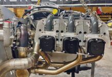
Just how cool is this 162F engine anyway? About 20 years ago, after struggling with trying to adapt marine Evinrude engines to a rotorcraft application and dealing with too much heat and not enough power, RotorWay began building its own powerplants–including pouring its own crankcases in its in-house foundry. The original design was very similar to a VW engine but with water cooling.
Now, the engine has developed into a significant and innovative piece of aviation equipment. RotorWay does everything from cutting its own cranks to machining all of the engine parts (although foundry work is now farmed out).
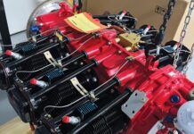
The end product is a 150-hp, 162-cubic-inch, four-cylinder, four-stroke, liquid-cooled design with dual electronic ignition, electronic fuel injection, and the patented FADEC (fully automated digital electronic control) system that monitors and controls all engine systems.
Earlier this year, RotorWay introduced the second generation of the FADEC system that improves the former backup system with a completely redundant backup unit. The original design was set up so that if the primary unit failed, the backup system kicked in. The backup unit had a less complicated computer that would not take advantage of any of the onboard sensors such as barometric pressure and ambient temperatures, but would simply default to fixed average settings making the engine still flyable, but not optimized. Now the new backup system is really just a mirror image of the primary system, using all the bells and whistles of its twin.
Before shipping the engine, RotorWay runs and calibrates each powerplant on a dynamometer, breaking it in somewhat and making sure it’s ready to fly. All the builder does is install the engine, hook up all appropriate hoses, electronics and mechanics, and fire her up.
Prior to pulling the engine out of the box, however, a little work must be done on the frame with the upper engine mount clevis casting. It must be bolted to the bottom of the square drive tubes underneath the main drive sprocket. For some reason, the construction manual has this step coming after the engine is in place. But that’s not the easiest order of things.
I installed the clevis per the instructions, then went back to the actual engine installation. There’s another item called the upper engine mount cup into which you glue and rivet a thick piece or rubber. This cup is then placed inside the main drive pulley on the engine and will be bolted to the upper engine mount clevis once the engine is in place.
Plunking in the Power
The entire powerplant weighs only 190 pounds, so three guys can install it (two if you’re careful). You can use a hoist if you want, but other than pulling it out of the box, it won’t do you much good as the unit has to be installed from underneath the helicopter. Just get another guy or two to help and you can probably mount the engine in less than an hour.
As you can see from the pictures, the engine must be set on top of a floor jack, balanced somewhat precariously on blocks of wood. The top piece of wood has a hole cut in it to allow for the oil drain plug, which is housed within a rubber donut and steel engine mount support ring. These two pieces must be put in place either on the engine or on top of the wood before you put the engine on the jack.
Using the floor jack, you raise the engine into the frame, making sure to route the drive belts over and around the main drive pulley on top of the engine. You must slowly raise the engine, watching every area of potential contact, making sure no part of the engine gets stuck on something it’s not supposed to.
You might have to rotate it slightly here and there to make sure all remains clear. Also, as you raise the engine, you’ll probably have to simultaneously push the jack forward bit by bit to move the engine into place.
Once the engine is at the correct height and with the upper engine mount cup mated and bolted to the upper engine mount clevis, three bolts must also be put in place in the lower engine mount area of the frame, through the engine mount support ring. After everything’s in place, you can move the jack out.
If the two pulleys are not at the same height–differing even slightly–the belts can either turn over or even run off the pulleys. Even if they differ by only 1/16 inch in height, they will run fine for a while, but. They are most likely to jump off when they unload at high rpm, such as when you enter an autorotation. At full rpm when the engine is cut back to idle, the belts get very loose and flap around an amazing amount. So this is when the belts will try to jump off the pulleys.
Usually only one or two will jump, so the helicopter will still fly. In fact, the machine will fly on only two belts. But this isn’t something you’ll want to deal with if you can help it. Changing main drive belts on a fully built machine is no fun. Make the two pulleys exactly the same height! You won’t regret the extra time spent.
Engine height is altered via shims on the lower engine mount area. Once you figure out if you have to either raise or lower the engine and how far, shims can be made out of aluminum stock, cut out from supplied templates. On my helicopter, I had to raise the engine 0.060 inch, using three 0.020 shims. Each helicopter is slightly different. If you’re lucky, you won’t have to shim at all.
Maintaining Tension
Main belt tension is altered by moving the engine forward or backward, and with the idler pulley. Even in the first few minutes of running, the belts will begin to stretch. It’s most important to monitor belt tension constantly and not let them get loose, even if you’re doing nothing but running the ship sitting on the ground.
Angling for Perfection
Now we’re at the most important and critical area of engine installation: height and angle. The manual and video tape show you how and where to make marks on the main drive pulley to match the height of that pulley with the secondary pulley. Both the engine pulley and the secondary pulley must be at the exact heights and at the same angles so the main drive belts will all be at the same tension and so that they will run true.
Loose main drive belts will slip, easily detected by a high pitch squeal either on startup or when you add power. If you let them get to the slipping and squealing point, the belts will then get dirty from lost and scorched rubber, and you’ll end up having to clean them more than usually needed.
And yes, you must clean them if they slip too much because the dirtier they are, the more they will slip. You don’t want dirty slipping belts when you make a hot approach. And that’s another thing: The belts will continue to stretch for maybe 30 hours or more depending on how you’re flying. And the more weight you add, the more they might slip. If you’ve been flying solo for 30 hours and the belts seem fine, when you add a big fat passenger and your belts are just barely tight enough to begin with, the extra weight will make the belts slip. So keep a good eye and ear on them! Within a few hours, they’ll stretch to a final point and usually won’t have to be adjusted again for their entire 500-hour life.
Back to Building
After the engine is in place, check both sides, making sure the valve covers don’t hit the frame. The torque link must now be constructed and assembled. It comes as a finished weldment from RW, and all you have to do is cut it to length, grind the top and bottom so it will fit within the brackets on the airframe, paint, add the rod end, bushing, and rubber and bolt into place.
Next you assemble the idler pulley, also known as the clutch assembly. It will be mounted via a pivoting bolt and bushing attached to the airframe with an actuator arm routed through the seatback ending as a Tee handle. After engine startup, the pilot engages the idler pulley or clutch that tensions the main drive belts the proper amount. The drive system on the 162F is unlike most other belt-driven helicopters in that the engine is never fully disengaged from the other components. As you can see in the pictures, four Vee main drive belts are driven from the small main drive pulley on top of the engine. These belts then head aft and turn the secondary unit which is basically a sprag or overrunning clutch mechanism.
The secondary then drives every other rotating unit on the ship via smaller Vee belts. It also powers the small drive sprocket on its top, which then turns the main drive chain and large aluminum drive sprocket attached to the main shaft. Even with the clutch in the disengaged position, the four main belts are still being driven and thus, so is the secondary and all connected devices. The idler pulley functions simply as a clutch or belt tightener for any operations above idle.
So at startup, the clutch handle has been disengaged and thus the belts are somewhat loose, allowing for an easier engine start and lessening the sudden jerk in the delicately tweaked rotor system. After the engine is running, the pilot pushes in the Tee handle in, which actuates the clutch arm casting, compressing the piston and springs housed in the clutch assembly’s spring tube weldment. The piston mechanism provides the correct belt pressure and allows the belts to run smoothly and with very little flap in powered operation.
When building the spring tube weldment, I tried to achieve a smooth operation of the piston. The absolute most important aspect of the idler pulley installation is mounting it so all its angles match that of the secondary and engine pulleys. That is, the three pulleys must line up exactly! To mount the swing arm of the clutch assembly, the builder must locate and drill two mounting holes for the 5/16-inch pivot bolt in two ears that have been factory-welded to the airframe.
In my opinion, this is one of the most difficult steps in building the 162F. If you drill one of the holes even 1/32 inch off center, the idler pulley won’t line up correctly with the other two pulleys. The manual covers the installation of this bolt with three sentences, but it’s not as easy as it sounds! I took my time to be sure of the location before committing the drill!
Note that the pivot bolt must be installed upside down from underneath. If you don’t, there will be no way to get it out once the oil bath is installed! Once the pulley and piston assembly is installed, belt tension must be adjusted via engine placement and also with the rod end at the end of the idler pulley’s piston.
The next section in the manual covers the tail rotor drive installation, but as we’ve said before, since I’m still stuck in a small garage with no room for the boom, we’ll cover that in our final construction article when the helicopter is at the hangar, almost ready to fire up!
Fan Drive Systems
Next comes the fan drive countershaft assembly. This is a shaft with a pulley on each end that is mounted on the left or pilot side of the ship. It is driven from a belt off the secondary, and in turn, drives the bottom belt, turning the cooling fan that is mounted on the bottom of the secondary. This fan is located within the fan shroud and rams cooling air through the radiator. (There is no longer an oil cooler housed in the fan shroud as there are in older RotorWay ships; oil is cooled with the new heat exchanger. More later.)
Both fan drive pulleys and the fan drive shaft have been machined to very close tolerances: so close, in fact, that ambient temperature where you’re building the ship will affect how the pieces go together. You must put a pulley on both ends of the shaft, then drill a hole for a 1/4-inch bolt. You use a “D” drill bit here so the bolt will be a tap-fit. Also, it’s a good idea to put the pulleys and shaft together after having kept the shaft in the refrigerator and heating the pulleys with a heat gun.
Be careful not to gall the parts when you pull the assembly apart for deburring the holes. Don’t twist the parts apart; use a small bearing puller. You should also paint the shaft since it’s polished metal as it most assuredly would rust after a while. You can temporarily mount the fan’s drive pulley on the secondary shaft to align the fan drive pulleys before final installation.
More Systems
The water pump is next in line. You’ll want to avoid hammering this pulley on the pump’s shaft as this could damage the seal inside the pump. It too has a close tolerance fit with shaft and pulley, so use hot and cold here as well.
The pump bolts on the right or passenger side of the ship and is driven by another Vee belt that should already be in place over the secondary during its final installation. Aim for another good line-up of pulleys.
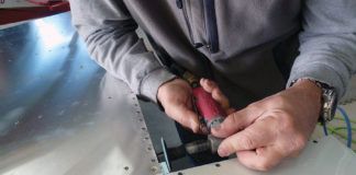
The last small accessory in this area of the ship is the alternator. It’s a 37-amp unit and of course uses a voltage regulator that you will mount to its underside. (For those who want a little more juice, RotorWay also offers a 50-amp alternator.) Before mounting the alternator, however, you must cut off some of its aluminum casing and file smooth. You must also cut off an existing connector and install a single-pin connector, later to be hooked in with the wiring harness.
A belt-adjusting strap must now be fabricated. This metal strap mounts between the alternator and one of the water pump’s mounting bolts and helps the alternator stay in place to maintain belt tension. This is the same belt that runs the water pump coming off the secondary, unlike older RotorWay ships, which used a tiny belt that ran separately off the water pump. The new setup is much beefier and more easily maintained and adjusted.
The Messy Part
Now we have arrived at the messiest part of the 162F: All hail the oil bath. I would guess that this will be an area that RotorWay will soon update. There’s really nothing wrong with the chain and oil bath. It’s just that there must be a better way to power the main shaft!
We have already installed the main shaft, at the base of which is the big aluminum drive sprocket. This sprocket is powered by the trilevel main drive chain, which is turned via the smaller drive sprocket sitting on top of the secondary. Both the sprockets and the chain sit in a fiberglass housing known as the oil bath, which also contains a big gooey mixture of oil and STP. The system works very well. It has for years on every RotorWay ship since the beginning. But it’s messy and heavy. So until something lighter and more simple comes along, we might as well install the thing.
You’re given three pieces of fiberglass: One is the lower oil bath pan; the other two are the front and rear oil bath covers. An improvement was made a few months ago in the cover design, one I’m looking forward to testing. We’ll get to that in a minute.
The builder sands the fiberglass to remove the rough edges, but also about 1 inch down both the inside and outside of the pan’s sides for gluing a rubber strip there. The long rubber strip that runs around the entire edge of the lower oil pan must be cleaned with acetone after being roughed up on the inside so the 3M two-part epoxy will adhere well. This particular glue needs to sit overnight before you mess with it again.
Next, we open the hole in the lower oil bath pan to just the right amount for the rear oil bath seal so that it will seat flush with its mating surface. It needs to sit flat, but we need enough surface to glue to.
This rear seal is delicate and must be handled quite carefully. Once the oil bath pan has been permanently located and bolted into place, the rear oil bath seal is glued into place inside the oil bath after it’s been carefully slipped over the secondary shaft. All rough edges must be removed from the shaft to keep from damaging the thin rubber in the seal. If the oil bath is moved once the rear oil seal is glued into place, it will leak!
The front hole of the oil bath pan has no seal, but goo won’t drip out because of the molded-in raised portion around the shaft. Also, since the oil bath is pretty big, the 1.25 quarts of liquid is spread pretty thinly. The actual mixture in the oil bath is 1 quart of motor oil and one pint of STP mixed together.
The tops of the oil bath just got a recent update that will save a lot of maintenance. When putting the lids on, you used to have to silicone them down onto the rubber strip, effectively sealing the bath but also making it difficult to remove the tops when you wanted to get in there again.
And yes, you do have to get in there. The tri-plex chain has the shortest part life of anything on the ship: 100 hours. Yuck. That means in 100 hours you have to take the lid off this thing and replace the chain. Pulling apart a well siliconed lid and rubber seal was no fun. I’ve cursed ’em a few times.
The solution? RW has extended the lid’s inner lip almost all the way down the inside of the bath. Supposedly, this allows the lids to be assembled, pushed into position, and held down with only springs, using no silicone sealant. (The springs aren’t new.) The new instructions suggest putting the front cover in place with silicone because you shouldn’t ever have to take it off. This setup sounds great and is a huge improvementif it works! I’ll let you know! But according to the handful of folks who have newly flying ships, the new lids don’t leak! Thumbs up.
There’s one other solution to this problem as well: a bigger and removable inspection window. Look at the pictures. You can see the large Plexiglas inspection window over the rear drive sprocket. To save yourself the hassle of taking the lids off, even if it’s now easier, just make the inspection window large enough to pull the chain in and out.
You’ll also have to locate the master link installation hole so that it’s underneath the window. With this larger window, you can see more of the chain as well as making it more accessible. To replace the chain, you only have to remove the 10 machine screws and the silicone that hold the window in place. The only problem with this is that it’s more difficult to wrap the chain around the main sprocket, and you can’t inspect the main shaft and main drive sprocket mating areas and attached bolts.
But it’s a good idea to inspect these bolts between changes anyway, so make even another inspection window just to the side of the shaft in the kicked-up portion of the oil bath cover. Look at the pictures. This window can be molded into shape by carefully heating a square of Plexiglas and bending it to match the contours. Hold it in place with machine screws, nut plates and silicone too. Mike Sherick and I both did this and I think it’s a good safety measure.
Next you’ll want to make the “rain guard” that goes around the main shaft and covers the hole where the shaft exits the oil bath. The sooner you make this thing, the better. With the oil bath permanently sealed, guess what happens when you drop a washer from up near the rotor hub! I bet it will decide to fall right in the oil bath. And if oil is in there, it’s pretty much gone! You’d have to disassemble the entire oil bath and poke around in the goo until you found it. That will set you back a few hours!
Keeping the Heat In
Now it’s time for a little bit of artwork. The exhaust pipes are stainless steel, and of course the assembly bolts onto the engine in four places. Before trying to mount it, however, I had to deburr and inspect the ends of the exhaust pipes, filing the triangle flanges perfectly flat.
Also, before mounting the headers to the engine, the pipes must be covered with heat wrap. The wrap is first be soaked in water, then wrapped around the pipes, being pulled tightly and uniformly laid out. This is some great stuff, easily put on, though time consuming, but you really need to plan your pattern to avoid too much doubling back or too many cutoffs.
If you wrap it correctly, you’ll only have to cut the stuff a couple of times. Clamp the ends of the wrap with the supplied high-temp tie wraps. There’s also nothing wrong with using extra tie wraps wherever you think the stuff might become loose over time.
After wrapping the pipes, you’ll have to let them sit for a day or two to dry. Depending on the temperature where you are, it could take a while for the thick places to dry! I had the thing sitting in the sun and it took a day and a half.
After everything is dry, you have to paint the heat wrap with high-heat coating spray paint. RotorWay supplies one can with the kit, but I don’t think that’s enough, especially considering you’ll probably want to recoat after the engine has run a while and the wrap has hardened. The paint coating tends to wear off a little, and it doesn’t hurt to shoot it again. You can either order more from the factory, or I’m told that paint for barbecue grills is the same stuff, easily found at places like Home Depot.
One safety note: The heat wrap is an area of construction where a lot of debate has taken place. There have been a few incidents of oil leaks in which the stray oil soaked into the heat wrap, causing fires. Some guys additionally put aluminum wrap over the exhaust pipes, greatly reducing the chance of virtually anything soaking into the wrap.
On my Exec 90 I have aluminum tape wrapped over and covering the cloth heat wrap, but I really haven’t decided if I will add it to this ship. RotorWay factory folks use only the cloth wrap, but they keep it painted and coated well to resist anything soaking in.
Antifreeze catching fire from a broken water hose is another concern, but with the new water hoses RW is supplying, as well as the suggestion of using Compleat–a propylene glycol antifreeze that isn’t supposed to burn–the chances of a fire are reduced. Talk with the factory if you have concerns, and check with other builders in your area. Race car guys deal with these same issues, so they’re a great source of information as well.
When the exhaust system paint is dry to touch, it is mounted to the engine using gaskets and three bolts at each point.
Cooling It
One of the unique aspects of RotorWay helicopters is the liquid cooling system. Considering that the factory is in Chandler, Arizona, not far from Phoenix, and that the factory does a lot of teaching with many hours of hovering, they need a ship that will hover and hover in near 100F weather while maintaining acceptable engine operating temperatures.
Necessity is the mother of invention, so we have one of the few aircraft with a radiator and a pretty efficient cooling system. In the 162F even more great strides were made improving the cooling system, and RotorWay and customers are maintaining operating temperatures in a happy middle green–somewhere around 170-180F both in water and oil.
The 162F is also the first RotorWay heli to do away with an oil cooler. Now oil runs through a combination oil sump/heat exchanger mounted just behind the pilot seat. This saved weight as well as making the radiator and fan shroud construction a lot easier.
The plans are thorough and clear in this area, showing the builder how to trim the one-piece fiberglass fan shroud and then mount the radiator inside it. Before mounting the shroud/radiator, the engine, exhaust pipes and secondary must be final-mounted and in their finished locations. (See now why you need to follow construction order?)
The fan should also be on the secondary shaft–not permanently mounted–but able to slide up and down the shaft so you can adjust and cut clearance for the fan blades on the fan shroud assembly. The fiberglass shroud ring is then located on the shroud, maintaining adequate fan clearance of about 1/8 inch between the fan blades and the ring. The builder might have to trim each fan blade slightly to allow it to spin freely and without risk of smacking the inside of the ring.
Because access to this area of the ship is so tight, centering the ring can be difficult as you can’t see everything at once. I found the easiest way to locate the ring was to make small wood wedges and squeeze them in between some of the blades and the inside of the fan shroud ring. This will maintain uniform clearance all around and will allow you to locate the ring and thus rivet placement accurately.
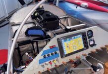
We covered a lot this time, and we’ll do the same in the next issue. We’ll plumb the oil, water and fuel systems, fabricate and mount the heat shielding and muffler, mount the gas tanks, and install the entire electrical system along with the instrument pod and all the instruments. She’ll then be ready to head out to the airport for final rigging! See you next time.
FOR MORE INFORMATION on the RotorWay International kit helicopter, contact the company at 4140 W. Mercury Way, Chandler, AZ 85226; call 602/961-1001; fax 602/961-1514; www.rotorway.com.


