Ignition timing is a concept simply expressed but slightly complicated to measure. And you will need to, both before you fire up the engine for the first time and during your annual condition inspections. Assuming your engine came with the mags and installed and timed, you might not have had the chance to test and adjust magneto timing during your build. Don’t worry, we’re here to help.
(Setting the timing of an electronic ignition system uses some of these concepts but not all, so we’ll save that discussion for another time.)
The basic steps are: Determine the proper timing of the engine as expressed in degrees before piston top dead center (TDC); find the crankshaft position that corresponds to TDC on the No. 1 cylinder, which is the timing reference; set the crankshaft at the position that corresponds with the desired timing; and check that the mags are actually firing at that point, and together.
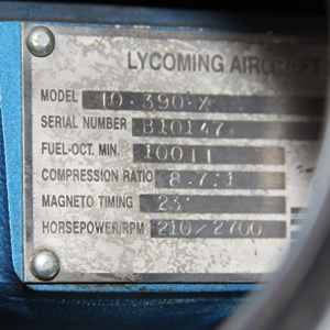
Generally, the magneto timing will be printed on the engines data plate, so look there first. If this an engine you had built for you or built on your own, you’ll know the timing figure by heart; if its a used engine or an engine in a used homebuilt, you’ll need to check the data plate and the logbooks. Typical engine timings are 20 to 25 BTDC (before top dead center).
Safety and Equipment
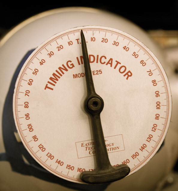
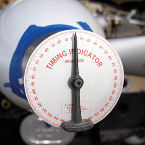
Remember that you’re working around a potentially live engine during portions of the procedure, so it’s imperative that you exercise due caution throughout. As for the equipment, you will need a timing indicator and a timing light. I prefer the Eastern Technology Corporation Model E-25 Timing Indicator (Aircraft Spruce Part Number 12-014014) and the Action Air Parts Deluxe Inductor Dual Magneto Timing Light (Aircraft Spruce Part Number 12-16901). (Note: The photos show different equipment that performs the same function.)
Finding TDC
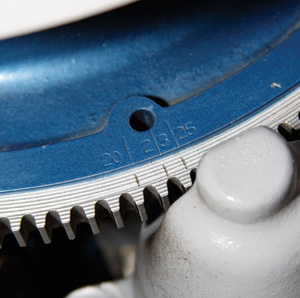
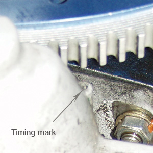
On virtually all certified engines there are timing marks you can use to determine TDC on the No. 1 cylinder; Continentals often use the case-split line extended to the crankshaft flange. Lycomings usually have timing marks on the starter ring gear (Photo 1) that align with a hole in the starter base. (For reasons of clarity, these marks are shown to the left, or leading side of the starter pinion; the reference mark on the starter boss is actually on the other side of the case. See the Timing mark photo, and pay no attention to the oil mist. This is what happens when a Lycomings crankshaft nose seal is in the process of failing.-Ed.)
These ring-gear timing marks work OK, but there is a method considered to be more accurate, which well elaborate on here.
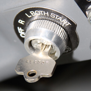
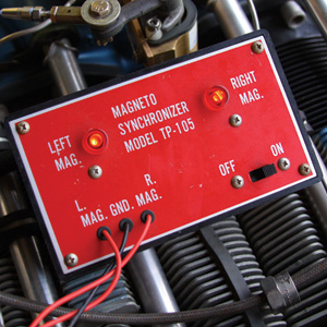
For safety, the first step is to ensure that both magnetos are switched OFF by being grounded through the ignition switch and P leads so that the engine cannot start or fire (Photo 2).
Remove the top spark plug leads and the top spark plugs from all cylinders. But we’re only looking for cylinder No. 1, right? Removing all of the plugs makes it easier to turn the crankshaft and helps prevent an accidental start.
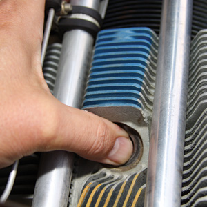
Locate the compression stroke, which is also the spark plugs firing stroke, on cylinder No. 1 by holding a thumb over that cylinders open top spark plug hole (Photo 3), rotating the propeller in the direction of normal operation, and feeling for the air pressure to build.
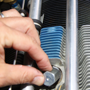
Ensure that the piston is not close to the top of the cylinder on the compression stroke and install the aluminum piston stop pin, which comes with the timing indicator, by threading it fully into the top spark plug hole in the No. 1 cylinder (Photo 4). If you have to move the prop to make room, rotate it opposite of the normal direction.
Install the open end of the timing indicator base (sometimes referred to as the flower pot) securely on the spinner by using the long rubber bands provided or small bungee cords and duct tape. Use protective tape as needed to ensure that the indicator base does not scratch the paint on the spinner (Photo 5). The moveable disk of the timing indicator should be perpendicular to the axis of the crankshaft with gravity holding the weighted end of the pointer down and the tip of the pointer pointing straight up. A small additional weight or plumb bob may be connected to the weighted end of the timing indicator pointer by a loop of string if desired for more positive pointer operation. It’s imperative that the pointer move freely and that the disk is square to the propeller flange for this method to work properly.
Rotate the propeller slowly in the direction of normal engine running operation until the piston comes to a gentle stop against the aluminum piston stop pin. This is crankshaft, propeller and piston position A prior to the piston reaching TDC.
Manually rotate the moveable disk on the indicator (the indicator base should not move relative to the propeller) until the 0 location on the disk is being pointed to by the upward pointed end of the pointer (Photo 6). You may ignore the TC and BC lettering on the moveable disk; these markings can be a source of confusion. You want to know that the moveable disk can be used to find specific degree locations among the 360 available as the propeller and crankshaft are rotated.
Next, rotate the propeller slowly opposite to the direction of normal engine running operation, while noting on the indicator disk how many degrees of rotation are completed until the piston again comes to a gentle stop against the aluminum piston stop pin. This is propeller, crankshaft and piston position B prior to TDC. Positions A and B have defined a small, but unknown number of arc sector degrees of the crankshafts rotation with the location of TDC on the compression stroke for the piston in the No. 1 cylinder being at exactly the midway point in this small unknown arc sector. The location of that TDC position can now be calculated. The number of degrees rotated through by the propeller while going from point A to point B in the opposite direction of normal engine running direction will be a large arc sector greater than 180 but less than 360. The number of degrees in the small arc sector between points A and B is equal to 360 minus the number of degrees in the large arc sector. Piston TDC location, the midway point between A and B, which are at the ends of the small arc, is determined by dividing the number of degrees in the small arc sector by two.
Again rotate the propeller slowly in the direction of normal engine operation until the piston is back at position A against the piston stop pin, and confirm that the moveable indicator disk has rotated back to where the 0 reading on the disk is at the pointer tip. The indicator base should not move relative to the spinner or propeller.
Rotate the moveable disk in the direction of normal engine operation until the disk has rotated the number of small sector degrees divided by two that was determined previously. This will place the 0 mark on the disk at the TDC crankshaft degree location-though the pointer wont indicate that yet. Remove the aluminum piston stop pin.
Rotate the propeller slowly away from point A in the direction opposite of normal engine operation until the 0 mark is at the pointer tip. The piston is positioned at TDC.
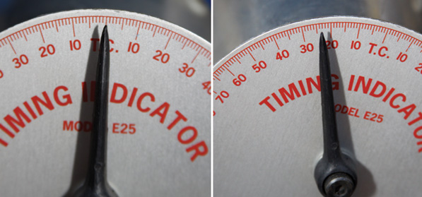
Now we want to move the piston to the specified number of crankshaft degrees before piston TDC (usually in the mid-20s) called for in the engine specifications (Photo 7). To do this, rotate the propeller in the direction opposite of normal engine operation until the pointer on the indicator is pointing at a point on the disk a few degrees beyond the specified number of degrees before TDC. Then rotate the propeller in the normal engine operating direction until the specified degree reading before TDC on the moveable disk is at the pointer tip. The piston is now properly placed for the spark plugs to fire.
The reason for going a few degrees beyond the specification degrees in backward rotation and then eventually returning to the specification point using the normal propeller rotation direction is that this removes the backlash or slack in the gears driving the magnetos. This slack can lead to an error of several degrees if not properly compensated for.
If either magneto is equipped with an impulse coupling, which retards magneto firing during engine cranking for starting, then the propeller needs to be rotated in the direction of normal engine operation until the impulse coupling(s) have snapped or released, and then the propeller is rotated in the direction opposite of normal engine operation until the pointer on the indicator is aimed at a point on the moveable disk a few degrees beyond the specified number of degrees before TDC. Then rotate the propeller in the normal engine operating direction until the specified degree reading prior to TDC on the moveable disk is at the pointer tip.
Now Let’s Adjust
Turn both magnetos ON with the ignition switch or switches. This ensures that the magneto P leads are ungrounded as they would be during engine operation.
Connect the black lead by clipping it to someplace on the crankcase for engine ground. Connect the red lead to the left magneto and the green lead to the right magneto. These connections are made to the P lead terminals on the exterior of the magnetos. Different magneto test boxes may have alternative color coding of the leads or none at all, but it is important to have the leads hooked up correctly so that you’ll adjust the intended mags when the time comes.
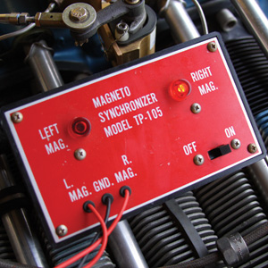
Turn on the inductor timing device. Being careful not to move the timing disk, move the propeller to a position thats just before the desired mag-timing point; you want to be ahead of the specified timing point. Both lights on the inductor timing device will be lighted if the points are closed, as they should be at this piston location (Photo 8). Recall that the act of firing the spark plugs by the magnetos is when the magneto points open, causing a collapse of the magnetic field in the magneto primary coil. The magneto timing box is simply a circuit tester with lights and a tone.
Move the propeller slowly in the direction of normal engine operation. When a magnetos points open, the light for that magneto will turn off and the audio tweeter will emit a signal-or change the tone, depending on your particular model of tester. That magneto would be firing a spark plug during normal engine running operations at this instant.
If both magnetos fire together, as indicated by the tweeter sounding and both lights turning off at the same time as the specification number of degrees prior to TDC on the moveable disk is at the pointer tip, the timing test is completed and no magneto adjustments are needed. If one leads the other (Photo 9), then adjustments will be necessary.
If adjustments are needed, ensure again that the propeller has been rotated in the normal operating direction to the specification spark plugs firing point. Then loosen the clamps on one of the magnetos, and rotate that magneto to a location so that magneto points are opening as shown by the inductor unit. Then clamp that magneto in place and repeat the adjusting operation on the other magneto. When both magnetos are simultaneously firing at the specification point before piston TDC then tighten the clamps on both magnetos.
At this point, it’s tempting to begin reassembling the ignition system, but a last check to see that the mags have not moved is always worthwhile.
Using a Digital Level
A third optional piece of equipment may be used to assist in the magneto to engine timing operation-a digital level. There is a wide variety of digital levels available and the operating instructions for each can be different, so it is not possible to give specific detailed directions, but here is the basic procedure.
The digital level should be taped or clamped securely to one of the prop blades or the forward spinner support disk. The face of the digital level should be perpendicular to the axis of the crankshaft.
Follow the steps outlined previously for bracketing TDC using the piston stop plug. Substitute or, better yet, confirm those readings from the timing disk with those from the level. You will need to zero the level for the first of these steps, and this reading does not correlate to a true reading of level with regard to the earths surface. We are instead setting a base reading on the digital level from which we can measure some degree differences.
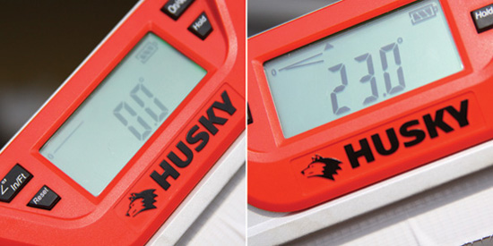
Once you have determined TDC on cylinder No. 1, reset the level to zero (Photo 10). Rotate the propeller several degrees in the opposite direction of normal movement beyond the expected ignition point. Then come back to it slowly by rotating the propeller in the normal direction of travel. Stop when the level displays the desired timing before TDC (Photo 11). There should be close agreement between the moveable disk readings and those on the digital level. It is up to the operators discretion to decide which reading is more accurate.


