This is a story of a simple thing overlooked. It involves a basic concept of aircraft construction and maintenance that I have shared with others, but managed to ignore on this occasion. That kind of day.
My GlaStar has a 150-hp Lycoming O-320. It’s a very straightforward installation, including a Cessna/Piper-style airbox with a forward-facing foam filter. It also had rudimentary, pure-analog engine instruments, since upgraded with the installation of a Dynon EMS-D10 with all-cylinder EGT and CHT measurement.
Previously, the single-point EGT would get to around “1500” and stay there pretty much no matter what I did with the mixture control; CHT, too, would hover around “300” much of the time. I put those numbers in quotes because I had zero faith in the absolute values. As such, I hesitated to go chasing after any given reading on such flimsy data.
The Problem
As soon as I got the engine monitoring installed, I noticed that the Number 4 cylinder’s EGT trended high on takeoff and initial climb, eventually dragging CHT along with it. That’s the classic indication of a lean cylinder. And by “high,” I don’t mean a little; it was sometimes 200 to 300° F higher than the others, which were clustered in a range of about 100°. The high EGT would eventually bring that cylinder’s CHT with it. By 1500 feet, it was not unusual to see Number 4 running 410° while the next-hottest was under 360° and the coolest was 330°.
Ultimately, that one cylinder dictated cowl-flap position to protect against excessive temps during climb. The other three cylinders had to be run too cool just so Number 4 wouldn’t get out of hand. I’ve come to expect cylinder-to-cylinder differences, but this spread from hottest to coolest is excessive in my experience and not supported by a visual inspection of the baffling system.
The overall temps were much better in cruise flight, especially with the throttle retarded. At lower power and higher airspeeds, things settled down so that the EGTs came more into a group and the CHT spread, still large, narrowed. At first, I thought, “Well, that’s how this engine in this airplane runs.” But it nagged at me and I couldn’t let it stand.
Troubleshooting next. Because the engine-monitor installation was new, I swapped wiring between the cylinders on that side of the engine. The problem stayed on that cylinder, so I had confidence the wiring was right. Swapping probes made no difference. Number 4 was still unhappy. It was real, not an indication issue.
Now what? An engine needs four things to run: fuel, air, spark and compression. I had already tried each mag separately in flight, and the indications tracked what you’d expect—a rise in EGT across the board. Both mags were properly timed, the plugs looked great and there were no other obvious misfires or other symptoms to suggest an ignition issue. A differential compression test ruled out problems with that cylinder.
What about air and fuel? I’ve experienced engines with induction leaks, which can be tricky to track down and remedy. But these usually present during partial-throttle operations, when the pressure differential between the manifold and ambient is greater. At full throttle, that difference is slight. But that’s where my problem was worst. I didn’t completely dismiss an induction leak—as proof I present my receipt from Aircraft Spruce for couplings and intake-port gaskets—but I set that possibility aside for the moment.
Fuel, then. In an injected engine, I’d go straight to the nozzles looking for blockage. I’ve seen engines have large spreads at high power but less of an EGT spread at lower power—all due to a partially blocked injector. I started thinking of the ways a carburetor could be induced to provide an imbalanced air/fuel mixture to the cylinders only under certain conditions. The carburetor doesn’t know what’s downstream. It just sends fuel in relationship to the volume of air, controlled via the throttle plate, and the mixture setting. I couldn’t see it.
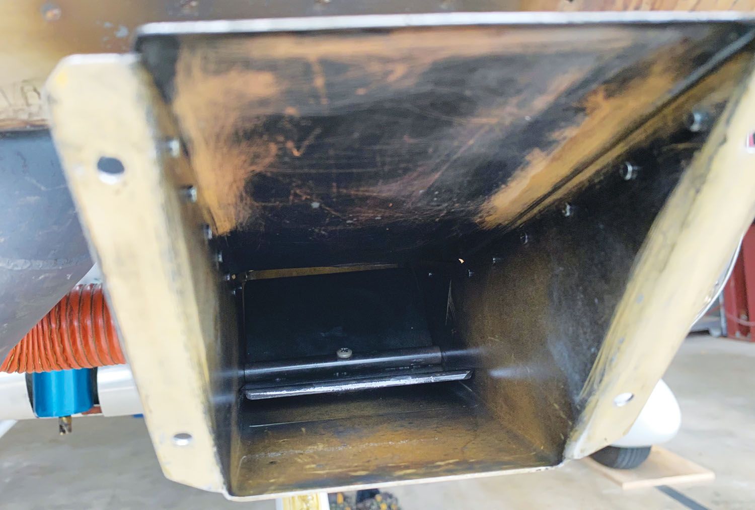
There had to be some kind of physical impediment either upstream or downstream of this newly overhauled carb. I wasn’t looking forward to disassembling the induction system to look for problems, so I started easy, removing the Brackett foam filter and cage.
Ah-Ha!
What do we have here? The carb-heat flapper was clearly sitting proud of the airbox floor, which means it was also open to the rear, admitting heated air to the carb at all times. I went over to the linkage and noticed that the cable was tight. Inside the airplane, the control was hard against the stop. A few minutes later, with a minor adjustment, the leading edge of the flapper sat flush against the floor, and I had an appropriate amount of control gap at the panel.
I still had doubts it was that simple. Could the flapper be so influential? Was it an airflow disturbance or the heat, or both? Had I just chased a ghost? The next flights proved it; the EGT spread was nearly gone, Number 4’s CHT came down into the pack and, as an added bonus, the engine seemed stronger now that it wasn’t inhaling a bit of heated (and, I daresay, unfiltered) air all of the time. As further proof, I could induce the anomaly by pulling on a bit of carb heat. Perhaps ironically, the more heat I applied, the less severe the effect. Meaning the flapper just happened to be at or near the worst-possible setting to make Number 4 run lean. Just my luck!
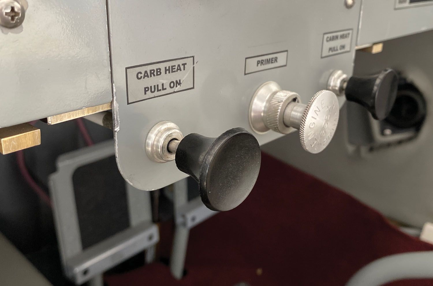
Moral of the story? Each engine control needs to have a bit of cushion so that whatever it’s managing hits the limits at the device and not the control. This very basic mechanical concept eluded me—and, it has to be said, at least a few of those who came before me with this airplane. The effects were no doubt obscured by poor instrumentation—it’s easy to think all is well and that, maybe, this just isn’t a particularly energetic O-320. What you don’t know…
So, in case you’re wondering, I did re-check every control in the airplane after this and made some other very small adjustments—including to my sense of “what else could be wrong?” If you allow it, the (re)learning never stops.


Yup. Years ago I was the fabricator, mechanic and test pilot on an extensive fuel system development project.
We were developing an emergency secondary fuel injection system on a Continental IO-0520 in Cessna 206 aircraft.
A key issue became apparent….the design of the IO-520 intake system for that particular installation had horrible airflow differences between cylinders. We proposed the same thing that GAMA Fuel Injectors later offered, but our company was too short-sighted to approve it. At least you can buy GAMA injectors today.
The airflow issue was from two problems: 1. cylinders were connected via stub intakes to a common runner on each bank, and 2. the 206 installation had a throttle plate that rotated around a fore and aft shaft, causing uneven air pressures.
Each of the 6 cylinders had different fuel flows as a result.
Glad you fixed your problem !
Ian Hollingsworth
Thanks, Ian. I am very familiar with that style of induction system, having owned a Bonanza with the IO-470-N. I was fully expecting some kind of obstruction in the intake tract based on what I noted on the engine monitor. I was really relieved when it was just the carb-heat plate!
I had a floppy air box that as found during the last annual. The bearings where it rotated were shot! My last two oil analysis also showed high silica. This was fixed and an improved induction STC installed but I now get 2300 static RPM vs 2200 (not sure if it is the STC or the box that was fixed. Also, the knob for the carb heat creeps just slightly open after about 20 minutes of flight. Reading your article has now got me thinking about all those items together. I’m going to fix the “walking” crab heat knob, recheck the carb heat flapper and make sure everything is as it should be. Then, I will check the oil analysis to see if the silica issue is resolved as this could have been from the leaky airbox. GRRRR!