This is the second in a short series about tips I’ve picked up over years of flying my own aircraft to airshows and how to weather the experience well. Last month we talked about timers and tiedowns. Now we’ll talk about propellers. Well, not the prop itself, which simply provides a sturdy mount for some items that finish out the “bling” of the display. We’ll also look at an aircraft band antenna, state and national flags, and a clean aircraft data sheet to tell the world about your airplane.
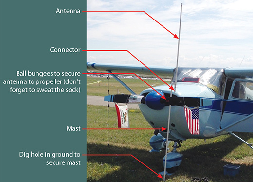
The aircraft at Oshkosh with the antenna, flags and signs as annotated.
Building a Better Antenna
Let’s start with the antenna. Why do we need one? Because most of us have a handheld radio to listen in to aircraft comings and goings. If we are camping (or even moteling or dorming), then we need something better than that rubber resistor that masquerades as an aircraft band antenna. In some tests I ran a few years ago, the minimum “goodness” of a rubber duckie was a reduction in range of 10:1 over a decent ground plane or dipole antenna. That’s a bunch when you are trying to listen to Fisk from the North 40 campground. Or even the heavy iron over Warbird Island inbound for the afternoon airshow.
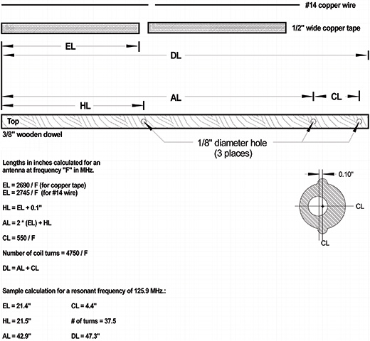
The engineering drawing to manufacture the antenna on the dowel.
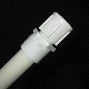
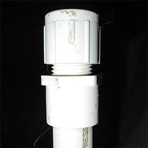
The top of the antenna itself. The dowel slips down into the pipe when the cap is unthreaded from the radome.
What’s better than a rubber duckie? There are two choices for simple antennas: ground plane or dipole. Ground plane is fine, but collapsing it for travel is a pain in the labonza. Dipole is also fine, but feeding it at the center is another pain in the nether regions.
So what to do? I chose dipole with some nifty thoughts for both feed and travel. The problem with feeding a dipole at the center is that the coax braid becomes part of the antenna and radiates part of the signal in a direction that you may not want. We can solve that problem too.
Here’s the deal: We will make this antenna waterproof and fairly strong. It is going to take some real stiff winds to break it, and even if it breaks, it will fail at a joint that is easily repairable. My best estimate is that it will withstand 60- to 80-knot straight-line winds before it breaks.
The top of the antenna mast. Note that the antenna mast may be of any suitable length to match the prop height.
Here is the design. This column will be very short on words so that the drawings can tell the tale. They say a picture is worth a thousand words, so this will be a 9000-word column: a thousand words and several illustrations.
The basic antenna structure is built on a 3/16-inch-diameter wood dowel. How long a dowel? Now it’s time to do some calculations.
What’s Your Frequency?
First, pick your center frequency. Just for grins, let’s pick the Oshkosh Arrival ATIS frequency of 125.9 as our “center” frequency. The antenna will work best at this center frequency, but as a function of how wide we make the antenna metal radiating elements, it will be a “good” (purely a subjective term) antenna the fatter we make the elements. You can use copper tape (available at most hardware stores) or #14 wire (strippable from house wiring Romex) to make the elements.
The bottom of the mast. Be sure to dig this end into the dirt (some of which remains) to keep it from moving around.
Here we go with the math. (Refer to the engineering drawing below.) First we calculate the length of the tape/wire elements. Using the formula in the drawing, each element becomes 21.4 inches long. Then we calculate the length of the 1/8-inch hole drilled from the left end of the wood dowel as 21.5 inches. Then the whole antenna length is 42.9 inches.
We will use RG-174 miniature coaxial cable for the wiring of the antenna and for the matching coil on the antenna dowel. The coaxial coil length will be 4.4 inches and will consist of 37.5 turns of coax wound on the dowel. This makes the dowel length 47.3 inches, and that is a good thing, because hardwood dowels come in 4-foot lengths. You can get longer dowels by special order, but they are expensive.
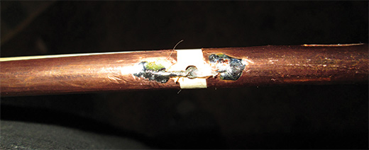
Connecting the coax to the antenna elements. Note the braid on the left going to the bottom element and the center conductor on the right going to the top element.
Now for the radome. This antenna structure will just barely fit into half-inch water pipe. If we can make water pipe to stand 60 psi from the inside, we can certainly make it waterproof from the outside. Using standard water-pipe fittings as shown in the photographs, construct the radome and antenna mast.
Hook up your radio coax to the BNC connector coming out the bottom of your antenna and you are in business.
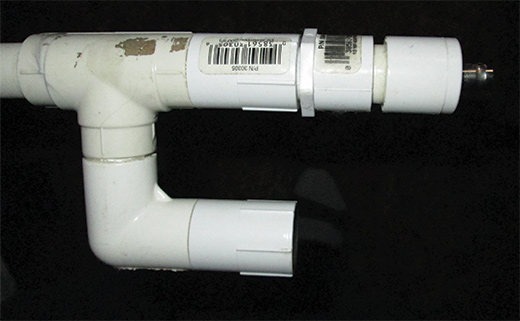
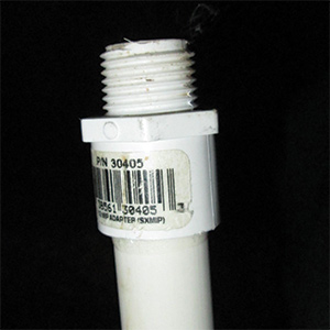
The bottom of the antenna showing the mounting arrangement. The mast screws into the threaded pipe connector on the left.
But the flags, Jim, the flags? Oh, yes, the Annin Flag company sells 12×18-inch state and national flags. You have to buy from one of their distributors (listed on the Annin home page www.annin.com), and you want the 12×18 size with header and grommets. Use 1/8-inch bungee cord to fasten the flag to the prop and put the edge of the prop in the exact center of the bungee knot to keep the brass grommets from dinging up the prop.
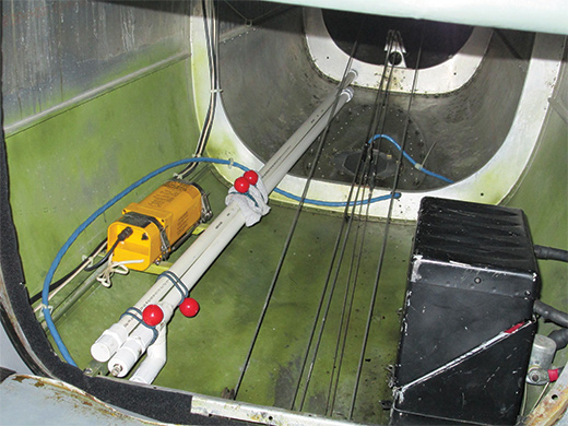
The disassembled antenna attached to the aft fuselage longeron with ball bungees. These bungees will also attach the antenna mast to the prop. The aft bungees are wrapped around a cotton sock, which is used to cushion the antenna mast from the propeller.
The piece de resistance? A custom “data plate” made with any word processing program. Laminate the data plate at a print shop and then tape or glue a sheet protector to the back side. Slip this over the prop and bingo: Passersby will know all about your airplane.
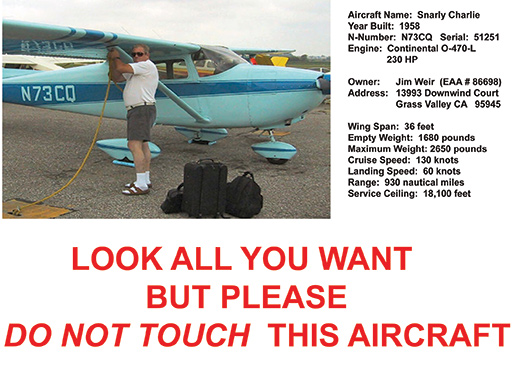
The artwork for the propeller data-plate sign.
OK, that’s enough of airshow strategies. We’ll get back to the electronics stuff next month. Stay tuned.


s")


