The alternator provides power to electrical devices (like lights and avionics) and also charges the aircraft battery. The voltage regulator continuously monitors the bus voltage and adjusts the output of the alternator. The regulator works when it is powered from a bus through a wire called the field wire.
Choosing the correct alternator and voltage regulator is an important part of planning your electrical system. There are two types of alternators to consider in your design: internally regulated and externally regulated. The typical newer automotive alternator is internally regulated.
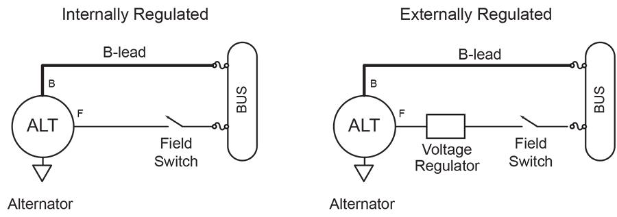
Figure 1. Internally regulated and externally regulated alternators. F = field wire input, B = B-lead output.
The voltage regulator does simply that—it regulates the voltage to the field wires in the alternator. Varying the field voltage affects the output of the alternator. Higher voltage means a stronger field to generate current, which means more output. An internally regulated alternator provides the same function, but the regulator is housed in the alternator itself. In Figure 1, you can see that internally regulated alternators are easier to wire, and you don’t have to mount a separate voltage regulator.
Externally regulated alternators have the regulator in a separate box outside the alternator. Most voltage regulators provide only the voltage regulation function, and some allow you to adjust the voltage level. The B&C LR-3C (www.bandc.biz) external voltage regulator provides three functions: 1) voltage regulation, 2) low-voltage alerting, and 3) overvoltage protection. It is generally regarded as a high-quality product that has been through years of field experience.
The diagrams illustrate how the alternator and voltage regulator work together. “F” on the alternator is the field input wire, and “B” is the B-lead, which is the power output. The field input of about 2 to 3 amps, combined with engine power, can output up to 60 or 100 amps depending on the alternator rating. When the field (alternator) switch is closed, the voltage regulator can read the bus voltage. If the voltage is low, the output on the field wire (to the F terminal) is increased. This causes a stronger magnetic field inside the alternator, which causes the output voltage to increase. The current flows out the B-lead to the main bus, causing the bus voltage to rise. The cycle repeats itself to maintain the desired voltage (about 14.2 volts).
Internal or External?
There is a long-standing debate in the Experimental community about the benefits of internally versus externally regulated alternators, and also about the use of automotive alternators. The table below shows some of the pros and cons of each type.
Automotive regulators have a failure mode that causes an overvoltage condition, and removing external field wire power cannot stop it. For that reason I do not recommend automotive alternators, even though they are less expensive than alternators designed for aircraft use.
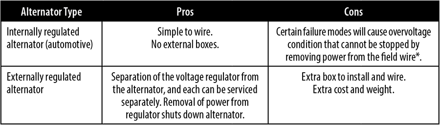
Internally Regulated vs. Externally Regulated Alternators. *Note: According to Plane-Power, their internally regulated alternators are designed to eliminate this failure mode.
Some common backup alternators are the accessory-drive mounted SD-20 alternator and the SD-8 PM alternator, both available from B&C Specialty Products. Plane-Power also makes a 30-amp pad-mounted alternator. The one you choose is driven in large part by the size of the loads you need the backup alternator to carry.
If you have two alternators tied to a single bus, only one alternator should be powered on at a time. Therefore, we refer to one alternator as the primary and the other as the secondary. If both are on simultaneously, they do not equally “contribute” to powering the loads. The alternator with the voltage regulator that is set to the highest voltage will provide all the current (sometimes called current hogging), possibly overloading the alternator.
Today’s Experimental aircraft are powered by either 12-volt or 14-volt systems. Often you hear systems described as either 12 volts or 14 volts. Why the difference? The reason is because the battery is rated at 12 volts. When the engine is running and the alternator is turned on, the alternator generates 14 volts, slightly higher than the battery voltage to keep the battery charged. So both monikers are actually true.
Overvoltage Protection
An overvoltage (OV) condition is initiated by a failure in either the voltage regulator or the alternator that causes the voltage to rise above a safe level for the avionics and other electrical equipment. Typically the overvoltage level is set at 16.0 volts for a 14-volt system and 32.0 volts for a 28-volt system.
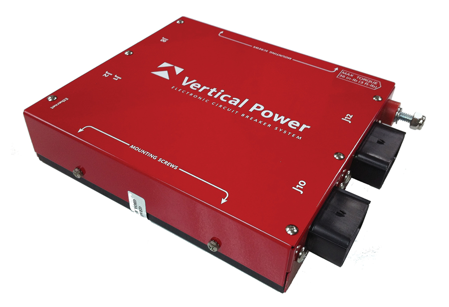
Overvoltage protection can be provided by the Vertical Power system.
Overvoltage protection is provided by the voltage regulator (if built in), a separate overvoltage protection module, or an electronic circuit breaker system such as the Vertical Power system. The overvoltage condition must be detected and resolved in less than 1/10th of a second, so it is not something you can do manually. If you wait longer, you risk damaging many thousands of dollars of electronics on the aircraft.
I highly recommend installing an overvoltage protection system. Fortunately, many aircraft-specific alternators include an OV protection system.
Frequent alternator field circuit-breaker trips may mean you have an actual overvoltage condition or it may be a loose wire. The first place to check is where the B-lead and the field wires attach to the alternator. Be sure to look at these visually (use lots of light) as well as give them a good tug. Look for burn marks at the connections. A loose connection can lead to surges that cause the overvoltage protection to trip.
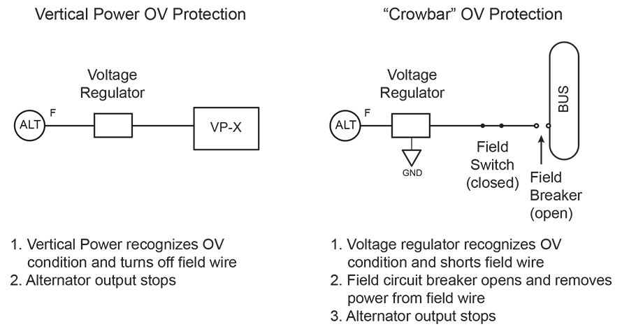
Figure 2. Different methods to detect an overvoltage (OV) condition.
There are several ways to detect and shut down an overvoltage condition. These are described in Figure 2, and the steps listed explain how that type of protection works. The microprocessor in the Vertical Power system detects the overvoltage condition and then simply turns off the field wire. The crowbar overvoltage system shorts the field wire to ground (visualize a crowbar shorting across power and ground wires), causing the circuit breaker to trip and shut off the field power.
Alternator Capacity
As with anything concerning custom airplanes, there is no hard-and-fast rule that applies across the board. The same is true for alternator ratings. A safe rule of thumb is to plan your electrical system to use no more than 80% of the maximum rated capacity. Some alternator manufacturers claim their alternators exceed the maximum rated load; if you want to be sure, contact the manufacturer directly.
The best way to verify that your alternator can support the aircraft’s electrical load is to perform a real-world test in flight. Once the plane is built and flying, turn on all the loads and watch the voltmeter on the EFIS. Leave everything on for at least 10 minutes (there’s nothing special about that number) and watch to see if the voltage remains constant. If the voltage declines, then the alternator cannot support the loads. If the voltage remains constant, then the alternator is sized correctly.
Another point to note is that the alternator is not always putting out its maximum rated capacity. It is only putting out enough current to power the loads (avionics, lights, etc.) and to charge the battery as needed. The voltage regulator is constantly adjusting the output in real time as you turn on and off the lights, motors, and other devices.
Low-voltage Indication
During flight, the normal bus voltage should be around 14.2 volts. A low voltage condition is most likely due to one of the following conditions:
• The alternator or voltage regulator has failed causing the bus voltage to drop from 14.2v to 12.4 volts or less (double for a 28v system).
• The electrical loads on the aircraft exceed the capacity of the alternator, which is unable to keep the battery fully charged. The bus voltage will slowly decline until the low voltage alarm is triggered.
• The alternator is turned off.
• The alternator field circuit breaker has tripped.
Tip: Set your low voltage alarm on the EFIS at 13.0 volts, and you will get a low-voltage alarm when the alternator fails.
While it is important to identify the low-voltage condition when it happens, there is no sense of immediacy like there is with an overvoltage condition. The aircraft will continue to get power from the battery for some period of time (depending on the battery size and the loads). Simply turn off the alternator switch, turn off non-essential loads, and turn on the backup alternator if installed. With modern avionics you should be able to load shed to get the total current draw below the backup alternator capacity, thereby providing you with an indefinite supply of power. If the electrical system is designed properly, an alternator failure should not become an emergency condition.
Alternator Current Sensing
You can optionally install a current sensing device to measure either alternator current output or battery charge and discharge rates. The current sensing device is typically a shunt or hall effect sensor and is provided with the engine monitor kit. For simplicity, we’ll use the word “shunt” to refer to both types of sensors.
A shunt can be installed anywhere you want to measure current. Typically a shunt is installed on the B-lead (the big wire) coming from the alternator to the main bus. In older aircraft, a shunt was installed to measure battery discharge and charge rates. The Vertical Power system has a shunt on each power output and can measure the current on each circuit individually.
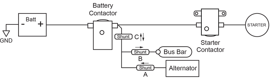
Figure 3. Three possible locations to install a shunt. Arrows show direction of current flow.
Shunt “A” in Figure 3 is installed on the B-lead and measures the alternator output in amps. Shunt “B” is mounted on the feed to the main bus, and measures current draw of all the devices on the bus. If a Vertical Power system is installed, shunt “B” is not needed. Shunt “C” measures the battery charge and discharge rates, in amps. Shunt “A” is the most common use and provides the most useful information.
A shunt is not required to tell if the alternator is working. You can tell if the alternator is working correctly by simply looking at voltage. If you see 14 (or so) volts with the engine running and the alternator on, then it is working. If you see 12 (or so) volts with the engine running, the alternator is not working or not turned on, or the total electrical load is higher than the alternator output.
Detecting Failure Conditions
Many electrical problems and failures can be detected just by looking at the voltmeter (typically displayed on the EFIS) and knowing how to interpret the number.
When the aircraft is off, the battery voltage is around 12.4 volts. With the engine running and alternator on and working correctly, it goes up to 14.2 volts. After engine start, turn on the alternator and watch as the voltage rises from 12 to about 14 volts to verify the alternator is working correctly. When the alternator fails, the voltage will drop back down to 12, triggering the low-voltage alarm. Therefore, the low-voltage alarm is often synonymous with a failed alternator. If the field circuit breaker trips frequently, it is often an overvoltage condition. The Vertical Power system specifically calls out an overvoltage condition, whereas traditional breakers trip without explanation.
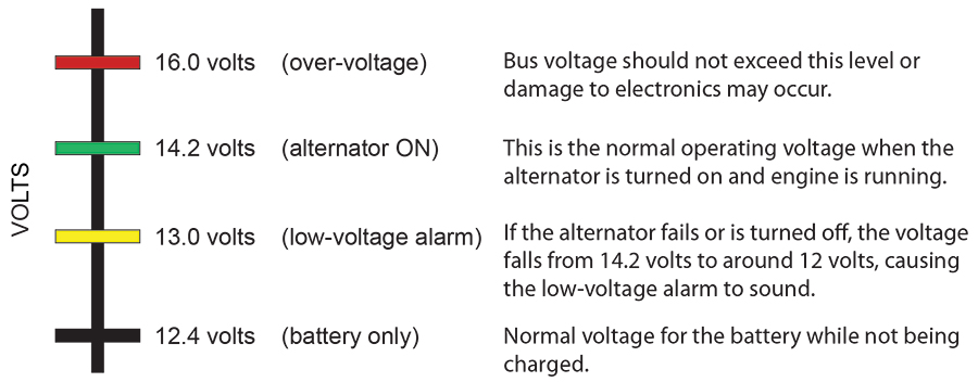
Figure 4. Important voltage levels to know. Double the values for 28-volt systems.
When to Turn on The Alternator
A question that often comes up is whether to turn on the alternator before engine start. Many pilots have a preference based on what they’re used to over the years. From an electrical perspective, having the alternator on during engine start does not do anything other than draw current. When the engine is off and the alternator is on, the voltage regulator sees low bus voltage (about 12.4 volts) and tries to raise the bus voltage to 14.2 volts by increasing the output to the field wire to its maximum capacity. Because the engine is not turning, nothing happens and the voltage stays at 12.4 volts while the voltage regulator is at maximum output, drawing about 4 amps of current. This also makes the alternator harder to turn and adds drag while the engine is starting (how much drag is added, I don’t know).
Based on this assessment, I don’t recommend turning on the alternator until after engine start. Get the engine running, then turn on the alternator, then turn on the avionics.
Read the Book
Hopefully this article has helped you understand alternator operation and how to read voltage levels to help with troubleshooting. It is an excerpt from my new book entitled Aircraft Wiring Guide. For more information, or to order a copy, visit www.aircraftwiringguide.com.


