
We knew we weren’t done with sheet metal when we completed the wings—and now that the steel tube fuselage was finished, here it was again. The entire front of the Bearhawk LSA is covered with, or constructed from, sheet metal. There’s a firewall, belly skins, cockpit floors and fuselage side skins. The cowling is all sheet metal too, as is the instrument panel. Rion Bourgeois and Philip Groelz, my partners in what we are now calling the ForeverHawk, were busy with other aspects of the airplane, so sheet metal fabrication fell to me.
Philip Groelz uses a Whitney punch to make small holes in the firewall flanges.
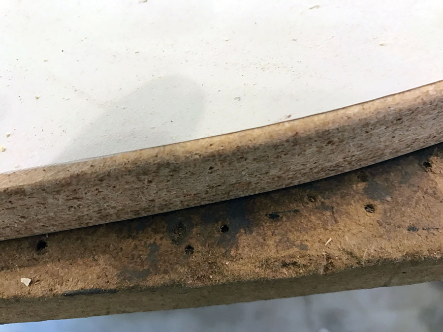
Some of the sheet metal parts are simple flat shapes, but others require bending on a brake, and some (with curved edges) require a form block. I started with one of the pieces requiring a form block: the firewall. The firewall is a natural break in the shape of the fuselage. Aft of it, sheet metal skins cover the forward bay around the pilot’s feet back to the rear of the door (on the left side) and swing-out window (on the right.) A sheet metal cowling runs between the firewall and a fiberglass nose bowl in front of the engine. It seemed logical to make the firewall first and work both ways from there.
Our firewall is made from a single piece of .018-inch stainless steel. The plans include a 1/10-size drawing of it—far too small to use. I was too lazy to enlarge it to full size by stippling dots on a grid pattern, so I asked a local copy shop to enlarge the drawing by a factor of 10 and print out a couple of copies on regular bond paper. They did, and the result was a good start, but the lines were now almost 1/4-inch wide. I worked that down to a thin pencil line that was my best guess and declared the result to be the shape of the ForeverHawk’s firewall.
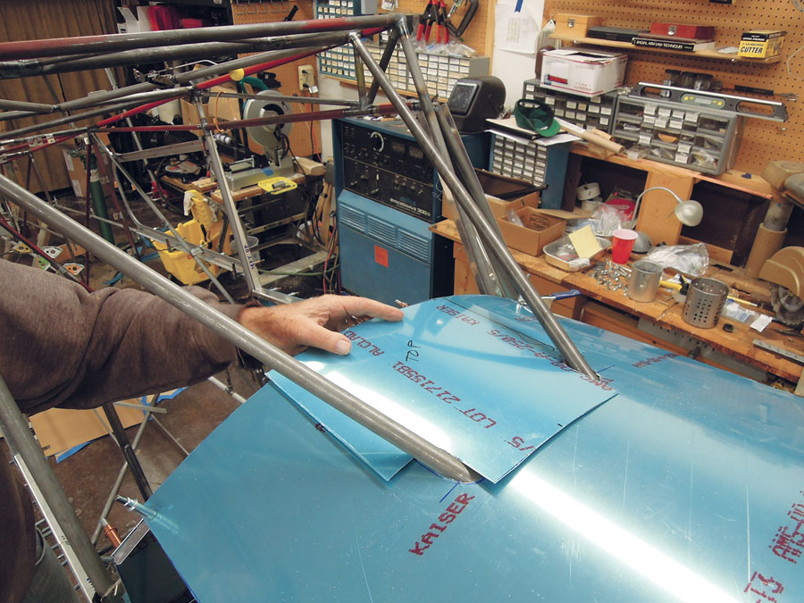
The upper skin underneath the windshield had to fit around two structural steel diagonals.
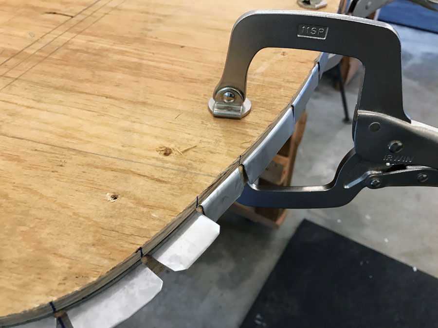
Spray adhesive fixed the paper pattern onto a sheet of 3/8-inch plywood, and I drew a vertical centerline and cut out the shape of half the firewall. Flipping the half pattern about the centerline ensured a symmetrical shape. I used drywall screws (surely the Creator fashioned drywall screws on the second or third day—otherwise how could She have held the rest of creation together?) to fasten the plywood pattern to a piece of -inch HDF that I’d band sawed roughly to size. A trip around the router table matched the HDF to the pattern, and another pass with a round-over bit gave a nicely radiused edge, and voil: a full-sized form block. I guesstimated a notching pattern, with notches closer together along the tighter curves, and marked that on the edge.
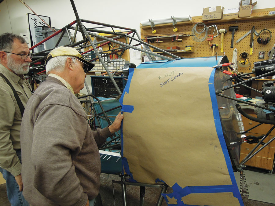
Rion Bourgeois (left) and Philip Groelz examine a paper template for the boot cowl.
The form block was then bolted to roughly trimmed stainless sheet with a pair of bolts directly on the centerline—the holes would be a handy reference later when we were aligning the firewall with the welded steel tube fuselage. I used a washer and Sharpie to trace around the circumference of the form block, creating a 5/8-inch flange on the stainless blank. The notching pattern was transferred at the same time.
I cut out the firewall shape with a Beverly throatless shear—a wonderful tool that has proved indispensable on this project. Thousands of RV wing ribs have made me pretty good with a Beverly, and I trimmed the shape of the firewall to within the width of a fine Sharpie line in less than five minutes.

Spray adhesive fixed the enlarged paper pattern onto a sheet of 3/8-inch plywood. A centerline was drawn, and the shape of half the firewall was cut out.
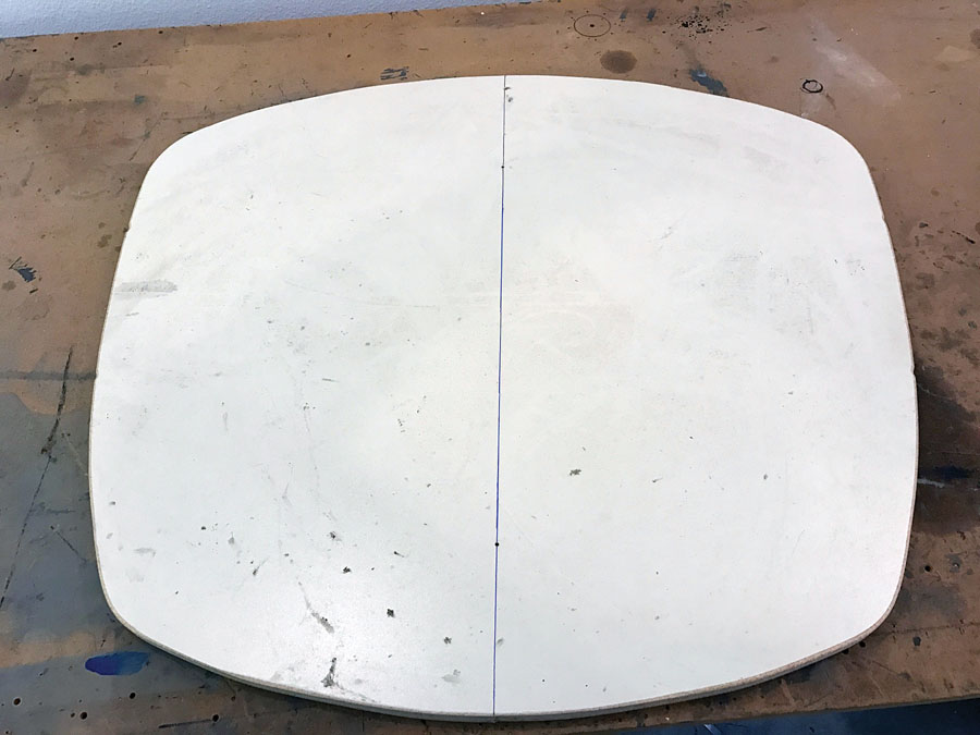
Flipping the half pattern about the centerline ensured the final form block had a symmetrical shape.
The notching took a bit longer. Drilling small holes in thin stainless is a true PITA—if the holes are within its reach, a Whitney punch is a much better tool for the job. With a dab of Boelube on the dies, it makes clean, almost burr-free holes quickly and easily. The apex of each notch was punched 3/16 inch and the notches cut with sharp aviation snips. All the edges were finished with a Scotch-Brite wheel on a die grinder, paying particular attention to the notches. Sheared stainless can slice up body parts as well as any knife, so I always handle it with tough gloves and spend a lot of time deburring the edges.
A round-over bit gave a nicely rounded edge to the full-sized firewall form block.
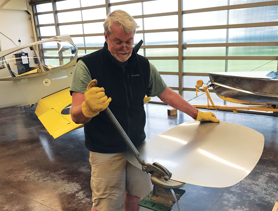
After the notches were cut, the firewall flanges were bent around the form block.
The finished firewall blank was clamped to the form block using the plywood pattern as the backer block. The edges were bent to the block with a plastic hammer. Stainless bends easily, with almost no spring back, so this job took just a few minutes. In the end, the firewall took five and a half hours from spray adhesive to finished part.
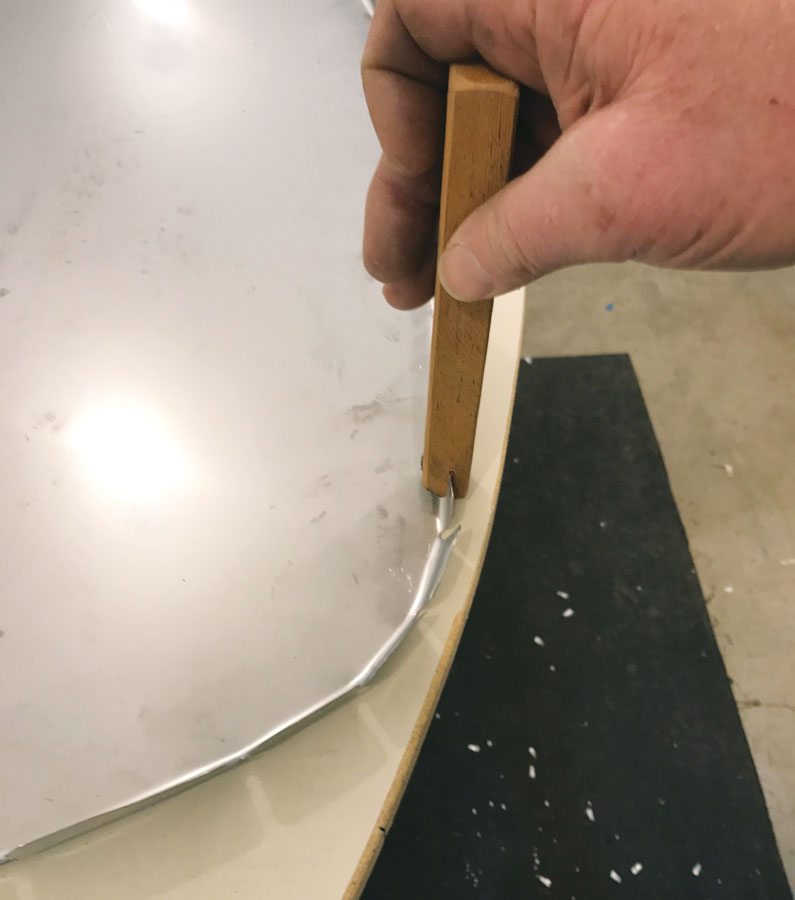
This simple flanging tool is nothing more than a stick of dense hardwood with a slot sawed into it and one edge rounded to fit the radius of the bend.
Cabin Floors
The cabin floors were much easier to do while the sides of the airplane were open, so I made them before starting the side skins. After spending far too much time prowling the internet for balsa-core panels, carbon fiber panels, etc., in an effort to find a material for light and strong floor panels, I finally punted and did—imagine it!—what the plans suggested and went with aluminum sheet. Cardboard patterns served to locate the various slots and cutouts for controls, seat rails, etc. Once the floorboards were in, we installed the seats temporarily and climbed in and out a few times, noting where our feet would have to land. I reinforced the floors in these places with aluminum angle riveted to the bottom side. Steel tabs with nutplates were welded to strategic places on the fuselage tubing to attach the floors.
(Now that we’ve mentioned tabs…when we started welding the fuselage, we had about 75 1.5×1.25-inch pieces of 0.062-inch steel plate punched with the three-hole patterns for nutplates. We wanted to be sure we had plenty…and we eventually had to make 30 more. There’s just no end to the things that have to be attached to the steel tube fuselage. We tried to think of a word for a group of tabs—if a bunch of crows is a “murder,” a flock of larks is an “exhaltation,” and a group of lions is a “pride”—well, what about tabs? We settled on an “infinity”…)

The cabin floors were much easier to fit before the side skins were attached.
With the floors in, I tackled the skins between the firewall and the door/window. The cross-section of a Bearhawk fuselage is not the simple rectangle created by the steel tube structure. In between the doorpost and the firewall, the shape of the fuselage varies continuously. There are a few dimensions on the plans to get you started, but it’s best to check the actual airplane before you commit to making parts. A few string lines, stretched between the fore and aft terminations—that would be the curved shape of the firewall at the front and the shallow vertical triangle of bent aluminum fastened to the rear doorpost—simulated the surface of the skin and defined the shape of the forward doorpost bulkheads. The idea is to establish the line of the side skins and build the bulkheads to fit, rather than the other way around. Once I knew what was needed, I bent the horizontal door and windowsills with a brake and used particleboard form blocks to form the curved doorpost bulkheads.
Because the side skins overlap the belly skins, I needed to make the belly skins first. This wasn’t difficult, as the skins are simple single-curvature rectangles, but the job did entail a lot of lying on my back, clamping, taping, and readjusting before I could finally drill the holes in the fuselage bulkheads and match drill the nutplates in the tabs. We used screws to attach the belly skins, rather than rivets, thinking that if we ever need to get to the control or fuel systems, it would be easier to come in from the bottom than to remove the seats and floorboards.
Ken Scott cuts the firewall using a Beverly throatless shear.
Side Skins
The best way to determine the shape of the skin was to use patterns made of stiff paper. Carton cardboard was too thick and regular paper too thin…something the thickness of a manila folder was just right. We found our material at the local feed store where it was used to separate loads on forklift pallets (we were soon on first-name basis with the warehouse guys because we never seemed to have enough paper and made several trips to scrounge up more). After several iterations and lots of tape and scissors work, we had our patterns. The Beverly shear quickly transformed a couple of large sheets of 2024-T3 aluminum into side skins.
After the side skins were drilled and Clecoed on, the last task was to make the upper skin underneath the windshield. This has to fit around a couple of structural steel diagonals. Instead of cutting long slots, we cut a rectangle in the rear of the skin and filled the gap with a removable piece that runs from the instrument panel to the steel tubes. We made a rough plywood model of the panel to support the aft edge of this skin, splicing in bits to fit the gaps where the panel didn’t fit the natural arc of the skin. The real panel would be cut to fit the arc.
Finally, all the sheet metal was on—and it was really starting to look like an airplane at last. That’s a bad airplane builder’s joke; now that it was all on, all 19 pieces had to come off for edge finishing, painting and dimpling—Rion insists on flush rivets. Sometime after the instrument panel is wired and installed, and before the engine is installed, it will all go on again. Until then, we’ve got plenty to do.


