
When I bought my Fisher FP-404 two years ago, it came with a serviceable but ugly tailwheel. I’m pretty sure it was a common furniture dolly caster that somebody had welded ears to, then drilled a bunch of holes all over it in an attempt to reduce the weight. Yes, it was more or less serviceable, but it shimmied at anything over a fast taxi, and the open swivel bearing meant it would drip grease and collect dust and grit.
Looking for an alternative, I didn’t find much. The standard full-swivel tailwheels used on classic light planes like Cubs, etc., are overkill for a plane with a 540-pound gross weight, and they’re expensive to boot. The thin “pizza cutter” wheels (which are actually snowmobile track rollers) used on Kolbs and other aircraft seemed a bit too light. Fisher offered a nice looking design, but it was out of stock, as were a couple of others I liked, including a nice-looking carbon-fiber tailwheel from Cured Composites. AeroConversions makes a nice one for Sonex aircraft, but it mounts on a round bar, not the flat spring I have on my Fisher, and it’s set up for a single pushrod, not dual chains and springs as I have.
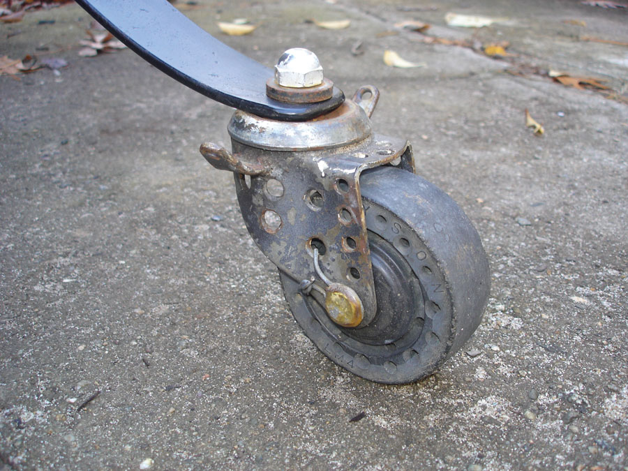
The original tailwheel worked, but was ugly! It looked like it was made from a furniture dolly caster with lightening holes to reduce weight.
In the end, I decided to make my own. I considered designing a detented full-swivel tailwheel, but the tail on my plane is so light (10 pounds) that it’s easy to pick up and move around, so the additional complexity didn’t seem to be justified. As it is, the springs I used are soft enough that using differential braking, I can turn just as tight as if it unlocked, while still retaining adequate control authority at other times.
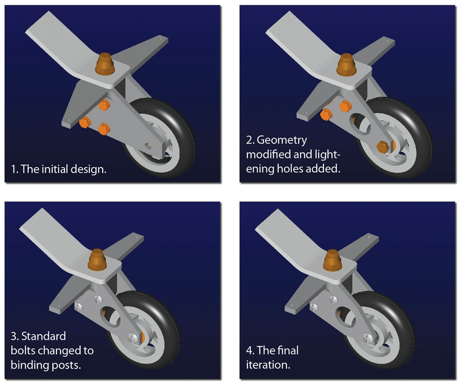
The tailwheel was designed with CAD and went through several iterations as the geometry, shape of the parts, and fasteners were refined.
I decided to start with a commercially available scooter wheel. These inexpensive aluminum wheels with polyurethane tires are available in several sizes, with a wide variety of colors and spoke shapes, and are readily available on eBay or other online vendors. A 100mm (4-inch) “Pro Scooter” wheel seemed about right. Not wanting spoke cutouts in stars or hearts, or a neon-colored tire, I ordered a pair (they typically come in 2-packs) of simple slotted wheels with black tires. Once they arrived, I could size the other parts.
Since my day job is designing machinery on CAD, I took the same approach for my tailwheel. The first step was to measure the wheel and create a CAD model so I could model the other parts around it. I used black Delrin (acetal) for the center pivot block. Delrin is a commonly used bearing material and requires no lubrication. Other plastics (nylon or better yet, MDS-filled nylon) could also be used. The design went through a few iterations as I refined the geometry and fasteners. I started with standard bolts holding it together, but switched to binding posts (sometimes called “sex bolts”) from industrial supplier McMaster-Carr for a cleaner look. When I was satisfied, I made a dimensional drawing from the model and took it into the shop.
With only four pieces to make, the design presented here could be made with nothing more than simple hand tools (hand drill, hacksaw, and file). A drill press would be a lot better, though, to accurately drill the pivot hole in the plastic block and the large holes in the side brackets (though the latter holes aren’t necessary). If you have access to a milling machine, so much the better. I used a tabletop “mill-drill” for final machining after roughing out the parts with a hacksaw and Sawzall.
Although the scooter wheel is a standard size, I don’t know how much the thickness may vary, so it should be checked in case the plastic pivot block needs to be made thicker.

After 60 hours of flying time, the wheel has been trouble-free on pavement and grass.
When drilling a hole the size of the large pivot hole in plastic, the drill tends to grab the plastic. To prevent this, the drill point should be ground back to a less aggressive angle (search online for how to do this). Also, holes drilled in Delrin tend to close up a bit and end up slightly undersize. You may need to “work” the hole a bit (or the steel bushing). You want an easy turning fit with no binding, but no wobble either. As I don’t have a lathe, I secured the bushing with a bolt and nut and chucked it up in a drill press, then used emery cloth for final sizing and fine Scotch-Brite for finishing.
The side plates are standard aluminum angle. Just about any alloy is OK, but I doubt you will find it in anything other than 6061. The 1.125-inch holes can be cut with a hole saw, or they can be left out; they only save a few ounces. The holes for the springs in the arms or “wings” should be figured according to your own installation. I initially made the arms longer than they needed to be and drilled several holes so I could try different positions. The outer position was less twitchy on the runway but didn’t let me turn as tight at low speed, while moving them closer in gave me great handling on the ramp at the expense of sensitive handling on the runway. I ended up using the inner position. One of these days I’ll cut the excess length off the arms.
The pivot is a piece of steel bushing stock cut to length. The AN8-30A bolt shown on the drawing is the right length for a -inch-thick leaf spring. If your spring is thinner or thicker, you may need to adjust the bolt length and/or the number of washers used.
Final assembly and installation is straightforward. Variations in the wheel thickness may require a different number and/or thickness of the washers on the axle between the wheel and the sides. Since the steel bushing is slightly longer than the plastic block, the bolt can (and should) be firmly tightened. The spring and/or chain attachment is up to you, and depends on your plane’s geometry. You may want to experiment, as I did, with different hole positions for the desired steering sensitivity. I ended up tapping the holes for machine screws, with picture-hanging loops from the hardware store to attach the springs. Since the screws were left slightly loose so the anchors would be free to pivot, locknuts on the bottom keep the screws from backing out.
As of this writing, the wheel has been on my plane for about 60 hours of flying time. Operating on pavement or grass, I’ve had no trouble with it.
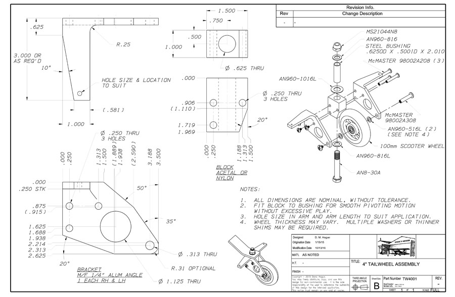
Interested in building your own tailwheel? You can download a full-size PDF file of this drawing.


Nice article, but the link to the plans didn’t work, are they still available?
The link now works, William.
Thanks for the great tailwheel plans. I just finished one without steering arms to be used on a Schweizer glider. It sits on the nose skid when the seat is occupied, so the tailwheel is only used for ground handling, never more than walking speed. The factory used a fixed tailwheel, a hockey puck with a 1/4 inch hole drilled in it. Much better to have a swivel tailwheel. Being a pack rat, I bought a new four pack of scooter wheels and bearings at a garage sale a couple of years ago for $3.00. I made binding posts out of 1/4 x 1 1/2 steel rivets from the local hardware store and drill and tapped the end 10-24. Thanks again for the nice design.
I too had a swivel caster in hand for my Woodstock Glider. Somehow I stumbled on this design. It is such an improvement on what is available for light aircraft. I made a few changes to fit my project, but following the prints will get you a great tailwheel. Very nice design. Not just for gliders!!!
I used these plans to build a tailwheel for my Legal Eagle ultralight. I absolutely love it, and it’s lighter than what’s called for in the original plans. I think the only thing I changed was the mounting bolt. I opted for a 5/16″ [.3125″] bolt to save weight. That called for a smaller diameter sleeve and a smaller hole in the acetal block.