I had another subject’s full column in hand for this issue, but when I get half a dozen questions in the space of a couple of weeks on the new-design ELT antennas, I become aware that there is a fair amount of interest in the question, and perhaps I should answer this question as a priority.
In 1972, Congressman Hale Boggs vanished on a private aircraft flight from Anchorage to Juneau. A very thorough search revealed neither hide nor hair of Brother Boggs (to this day). Mrs. Boggs ran in the special election to fill Boggs’ Congress seat and won. Given the major hassle she went through having her husband declared dead when they couldn’t provide the body of the dearly departed, sure enough, the next year (1973) a Congressional mandate came down requiring ELTs on all civilian aircraft. The effort was spearheaded by the aforementioned widow of Brother Boggs. And probably rightly so.
The frequencies chosen for this task were 121.5 (the civilian com band emergency frequency) and 243.0 (the military com band emergency frequency). This was an unfortunate choice (note that the military frequency is the second harmonic [x2] of the civilian frequency). Nothing can be harder on an antenna designer than making an antenna that will efficiently radiate simultaneously on both the fundamental and the second harmonic. The fundamental and third harmonic? Piece of cake, as we will see in a bit.
For the old 121 and 243 frequencies, we generally cobbled something together for metal aircraft that consisted of a short vertical metal spike for the 243 frequency and a series short metal coil that electronically decoupled the military frequency but fed a taller series spike for the 121 frequency. It worked…sort of…but the coil had a nasty tendency to vibrate at its acoustic resonant frequency, crack and depart the airframe. On plastic airplanes we had it a little easier to put two dipoles for the two frequencies together, joined in the middle, and match (sort of as best we could) the two antennas fed with a single coax inside the plastic airframe.
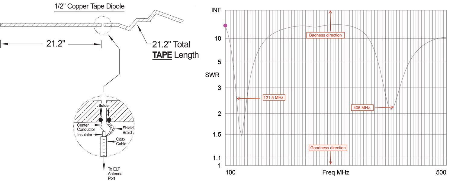
In 2009 the decision was made to completely drop the 243 military frequency from ELTs and substitute 406 MHz in its stead. The decision was made for a couple of really good practical reasons and one really unfortunate one. The practical reasons were that the 243 military frequency was, for all practical purposes, never used to find a downed civilian aircraft, and that frequency band was much more likely to bounce off of rocks, hills and other geographic artifacts. On the other hand, the 406 frequency wouldn’t bounce off of much and there were satellites in orbit that could detect that frequency. The practical reason that nobody thought about was that you could use the same antenna (no modifications) on 121 and 363 MHz (not 406) without any trouble at all. More—much more—about this later.
The 121 frequency was kept because a lot of Search and Rescue (SAR) units had direction finding “DF” gear and had lots of experience tracking 121.5 ELTs. The 406 frequency was added because of the precision of location of the ELT. Put it this way: 121 would allow you to search and find a crumpled fuselage somewhere inside of a city block, while 406 would put you inside the pilot’s chair in the fuselage.
Now the problem resolves itself to designing an antenna that will radiate these two frequencies efficiently. Allow me to illustrate the problem.
A VOR/LOC antenna, at 113 MHz for a quarter-wave element length (the rabbit ears on the top of the vertical stabilizer on metal aircraft) of about 24 inches each side of center, provides a perfectly good antenna from 108–118 MHz, including the ILS localizer frequencies from 108–112 MHz. The corresponding glideslope frequencies, centered at 330 MHz, are exactly a multiple of three times the localizer frequencies. Guess what? Quarter-wave antennas are every bit as good as three-quarter wave antennas. That is, if you cut an antenna for one frequency, it is also excellent at three times that frequency (and five times that frequency, and seven and nine and 11—all odd multiples of the original frequency).
Well, drat, the ELT folks weren’t quite as smart as the glideslope folks back in the late 1940s in assigning frequencies, but they came close enough.
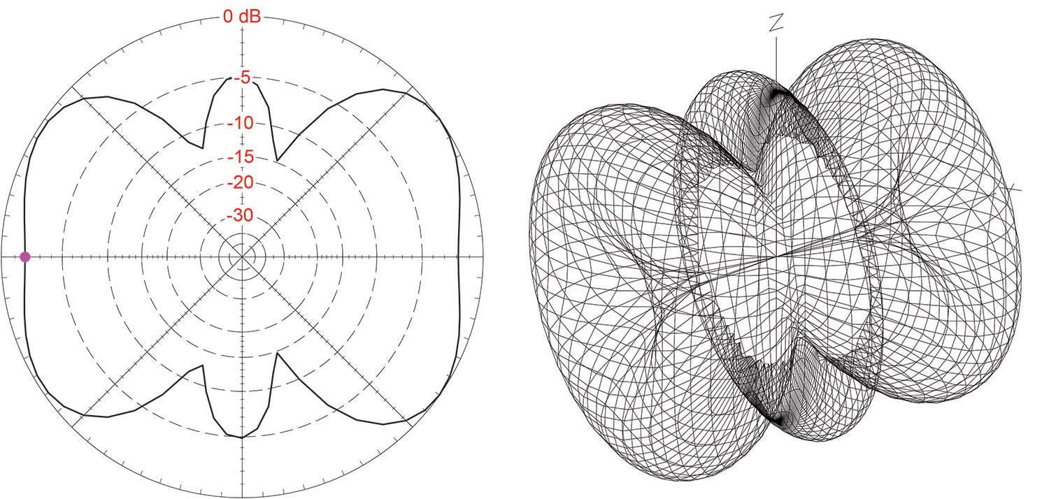
We can make a single antenna for both 121 and 406 frequencies if we are willing to make a bit of a compromise that the antenna will not be absolutely optimum for either signal but will be close enough that it will be perfectly usable for both.
What is this compromise? To use a term I’ve used before in this column, it is “VSWR” (voltage standing wave ratio). In essence, it asks how much of the power you send down the line is radiated versus how much gets sent back to the transmitter. For those of you more versed in engines than transmitters, consider that a propeller designed for an O-320 will be slightly different from that for an O-360. However, if the prop maker makes it for a compromise O-340, it won’t be quite as good on an O-320 or the O-360, but for all intents and purposes it is so far down in the noise that you won’t see the difference. Same with both of these antenna designs.
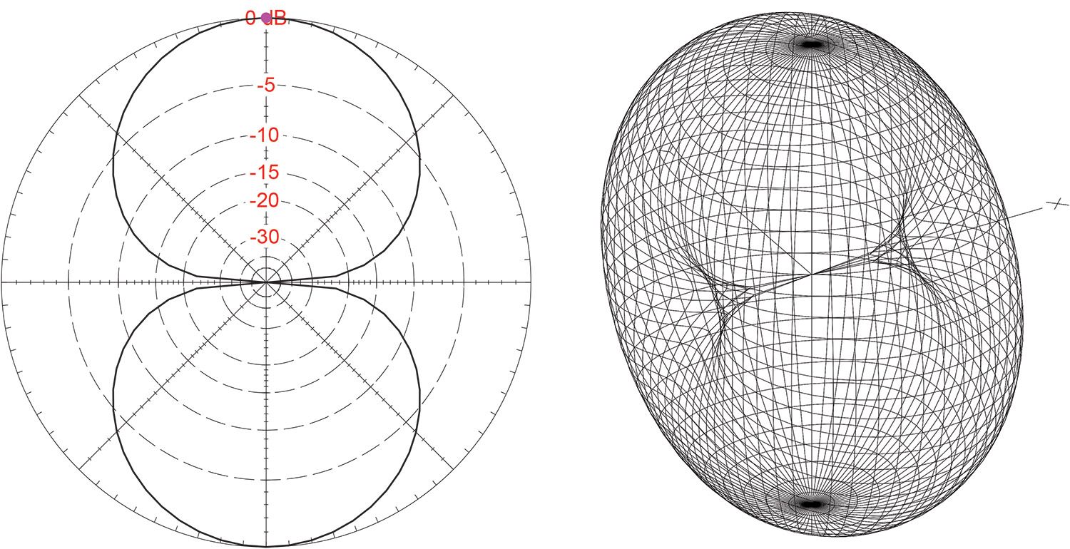
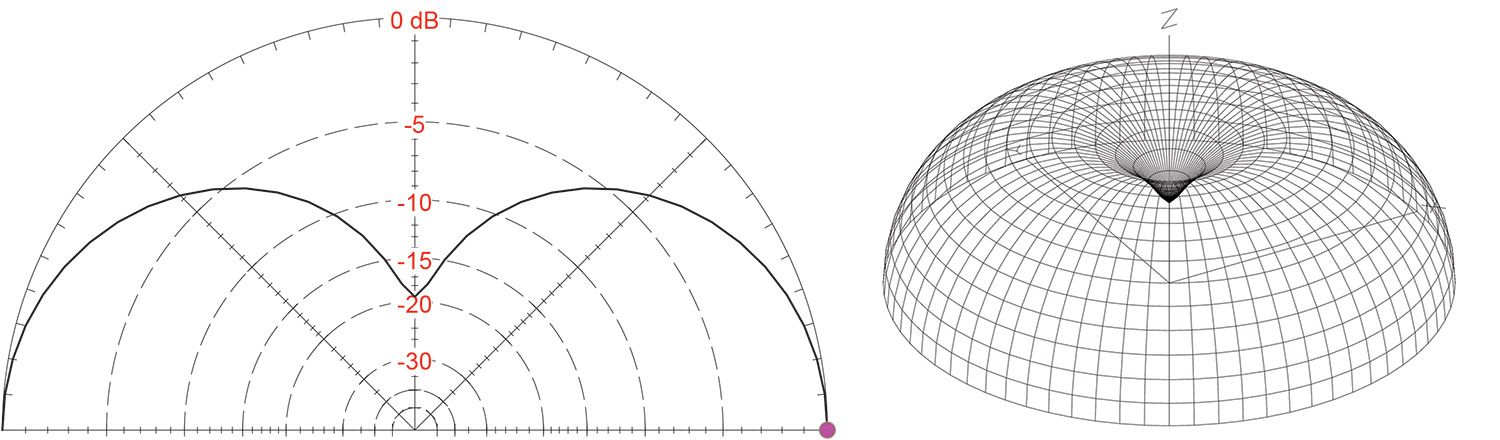
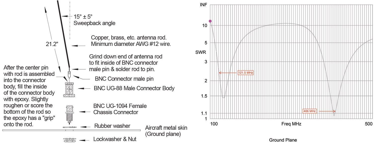
That makes the designs really simple. For a metal ship, you simply make a spike antenna 21.2 inches long and bent back (aft) at approximately a 15° angle. Any wire heavier than AWG #14 will work just fine. For those of you that want to geld the filly, you can use my favorite antenna material, half-inch copper tape, gin up some sort of fiberglass structure, and your antenna will work a little bit better electrically and be a lot better aerodynamically.
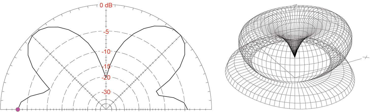
For those of you with plastic ships, a plain old half-wave (two quarter-wave elements made of half-inch copper tape 21.2 inches long ) dipole will work well. Simple, cheap, and works perfectly. You can bend it around, twist it to miss structural members or lay it out perfectly straight. Just remember that maximum radiation is at right angles to the antenna and practically none off the ends of the elements.
The question has often been asked of me, “Should the ELT antenna be mounted horizontally or vertically?” The answer has always been the same: If you can tell me the orientation of the crumpled remains of the fuselage in the middle of the dust cloud when you really need the ELT, I can tell you the orientation. In my experience, a random guess is every bit as good as anything else.
Next month I hope to get back to one of the final chapters on the HOG project—economically converting 110-volt fluorescent hangar fixtures into 12-volt LED fixtures. Until then…Stay tuned…


Hi Jim,
Had the T28 around the corner from you. Moved to Coeur d’Alene a year and half ago.
Did you ever design an AOA with audio output like a glider Variometer? I did design and Variometer with audio many decades ago. Worked great.
I think 406 was picked – because we were already using it at sea to replace 121.5 which was notoriously prone to false alarms. The COPASS-SARSAT satellite constellation was already set up for 406.
If I have one thought – it is that the alphabet soups did pilots a disservice by insisting on retaining 121.5. It meant that the efficiencies of volume production for 406 were long time coming (they have possibly just started to arrive) and the benefits of sending a GPS location and much more precise DF’ing were lost to many who might have benefitted from it.
That said – unless you read the directions and TRULY mount the ELT to the structure so it triggers correctly in a crash and there is sufficient strain relief in the antenna cabling – no ELT will work for you.