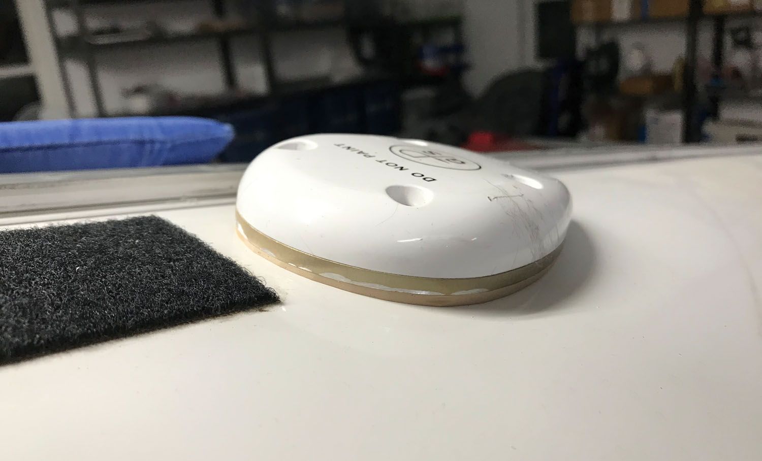
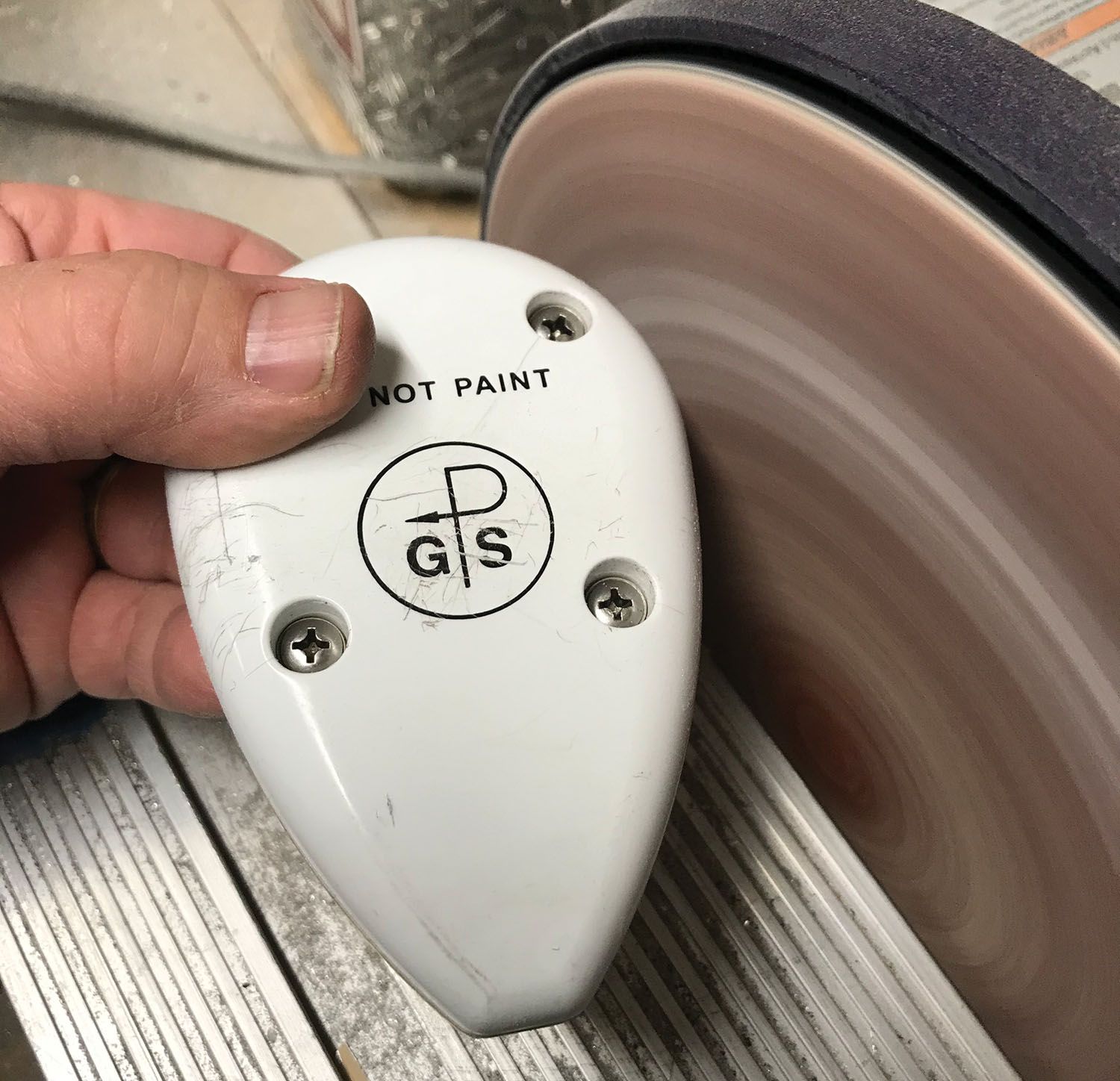
 A long time ago, when homebuilders began installing Garmin 430s—the most popular IFR GPS/nav/com of the day—we were mostly left on our own to install the somewhat large GPS antenna. Garmin’s most important instruction was “DO NOT PAINT,” as proclaimed on the antenna itself. Many of us decided that the easiest thing was to mount them on a flat shelf underneath a fiberglass cowl, in front of the firewall—they were hidden, secure and worked great!
Then came WAAS and GPS approaches with vertical guidance. To get there, you had to upgrade your box to WAAS and install a new antenna. The new antenna looked just like the old one, but many of us found out that it was far more sensitive to interference. And then came ADS-B and the need for solid GPS positions all the time. That the FAA can monitor the “goodness” of your GPS position makes it hard to sweep those “GPS position lost” messages under the rug.
So, at least for me and my RV-8, it was time to move the antenna. This would also solve a minor vexation I had put up with ever since the airplane was new—the fact that the antenna got in the way when installing or removing the rear cowl pins. (That’s a consequence of the “law of changes,” which says anything you change when building an airplane will come back to bite you.) So, yeah, I wasn’t unhappy to move the antenna to the fuselage behind the passenger.
The only problem with this is, of course, that the base of the antenna is flat and the fuselage there is curving. Drill holes for the coax connector, place the antenna there and it rocks back and forth with a gap under each side. I experimented with pushing it down tight, and sure—it worked. But it was clear I was deforming the fuselage skin, and this would affect the canopy fit, and probably the load-carrying capability of the monocoque design. What I needed was a shim that was flat on top, curved underneath, fit the antenna perfectly and wasn’t too thick. I’ve been around fabrication long enough to know that trying to build something out of aluminum was going to take way too much work and time, and a 3D scanner/printer was beyond my means and experience. But I could form a shim using fiberglass resin and filler—so that’s what I did.


It really doesn’t take that long—especially if it is warm enough to kick off your chosen resin in a reasonable time. But, being that I have an unheated shop in the high desert and it was February, this could have been a problem. I still have some halogen work lights that do a great job at converting electricity into heat and one placed inside the fuselage raised the skin temperature to about 100° F—perfect for resin curing.
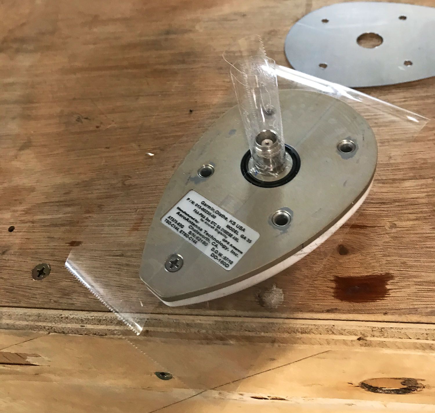
The process works like this. First, I drilled holes for the antenna in the skin—both for the coax connector and the mounting screws. After deburring the holes, I taped over the area with clear packing tape. I also taped up the bottom of the antenna and the TNC connector. This tape serves as a release plane for the shim because the resin won’t stick to it.
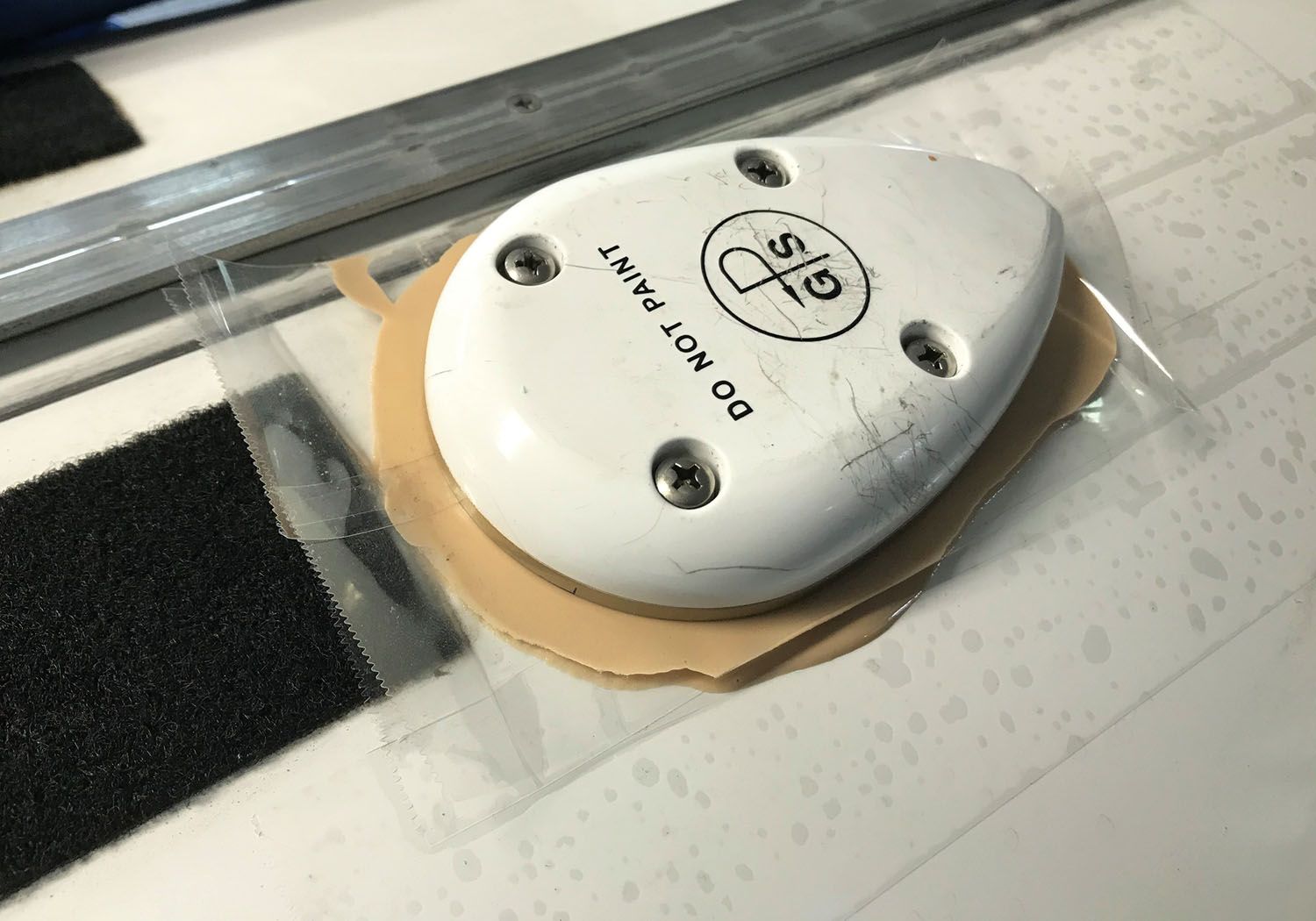
I next mixed up just a little resin and added micro-balloon filler until I had a very dry mix—more like putty than toothpaste. I didn’t want it to run at all. I then slathered the mix onto the antenna—more at the edges than in the middle because that is how the shim would be shaped. With one smooth motion, I smooshed the antenna on to the fuselage and inserted the mounting screws after giving them a light coat of WD-40 so the resin wouldn’t bond to them. I didn’t put nuts on—I just used hand force to push the antenna until I had a nice squish out of the goop all the way around, and the centerline of the antenna was almost flush to the skin. Then I went to dinner.
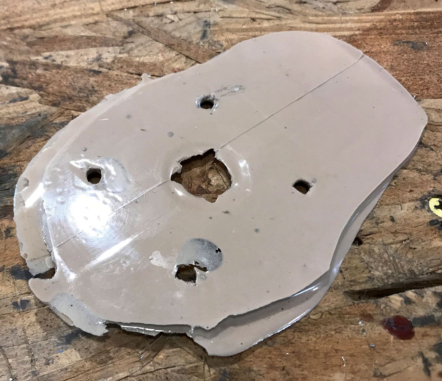
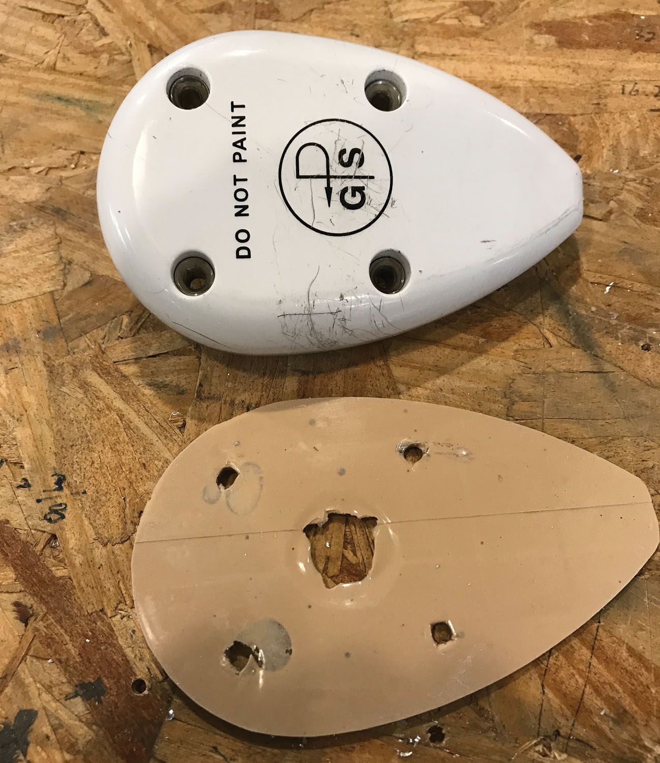
After about two hours (hey, it was an airpark dinner with lots of hangar-flying to be done!), I came back and the warm temperatures had hardened the shim nicely. The antenna popped right off due to the release tape and the shim popped off the tape on the fuselage as well. After removing all the tape residue, I attached the shim to the antenna with the mounting screws and nuts and headed to the disk sander, where I removed the excess material and shaped it perfectly to the base of the antenna.
Then it was back to the airplane, where everything bolted right up! I now had a perfect fit of the flat antenna to the curved fuselage—and per the note in the Garmin antenna manual, grounding was not an issue, as it is grounded through the coax connector.
While getting a good fit for your antenna might seem like a daunting task, the process really only took about a half hour, spread out over an afternoon of work—and you can do other things while the resin cures. It’s nice to have a good fit and no distortion of the sheet metal—it shows an attention to detail and craftsmanship that will impress those airpark neighbors.


Great article and timely. Thanks Paul and Kitplanes.
Did you weaken the sticky side of the packing tape that you put on the fuselage? It’s pretty powerful stuff and I wonder about taking up the paint.
I’ve honestly never had a problem with it lifting paint – of course, there can always be a first time, so if it worries you, there is also vinyl “bundling tape” in 2” widths at the home improvement stores that does a good job at releasing, while (subjectively) being lower adhesion. It is also thicker than packing tape, so will change your sizing just a touch.
I just went through all of this myself on my RV9A. After much thought I made the decision to cut the holes right on the centerline behind the supertracks extension. I carefully matched the curvature using some techniques and pictures I could share that worked very well on the doubler. However, with many discussions and reading Garmin specs, they really want to have the GA-35 bonded to the bare alum skin for best performance. So, I ordered some conductive foam that is 0.062 thick from https://www.eastcoastshielding.com. This will squeeze down and make up the 0.050 or so curvature gap and also be hyper conductive to bond to the skin to provide that minimum 8 inch ground plane radius that Garmin wants.
A better filler is to mix 1/8 or 1/4 inch chopped glass to the epoxy along with a cab-o-sil filler for a matrix with better mechanical strength.