 Rule number one for building the SubSonex: Build from the inside out. Rule number two: Never close anything until you have no choice but to do so—you might need to access something on the inside.
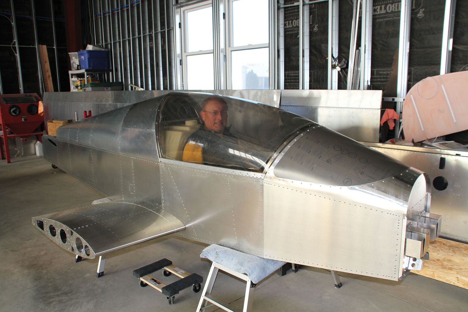
![]() The SubSonex is small; even experienced builders who come to visit the shop remark at just how diminutive it really is. I’ve built an RV-3, a single-seat, single-engine airplane that is dwarfed by my RV-8, and even compared to the -3 the SubSonex is small. Short in stature, you will get tired bending over to work on the fuselage if you let it sit on its gear. Workstands are important, not only to stabilize the project but to get it at a height where you can work! You’re going to want the fuselage high enough so that you can work underneath it on a creeper to install—and then cycle—the landing gear. Getting the belly about 18 inches off the ground seemed to be about right for us, and once we had it there, that’s where it stayed until it was time to roll it around.
The SubSonex is small; even experienced builders who come to visit the shop remark at just how diminutive it really is. I’ve built an RV-3, a single-seat, single-engine airplane that is dwarfed by my RV-8, and even compared to the -3 the SubSonex is small. Short in stature, you will get tired bending over to work on the fuselage if you let it sit on its gear. Workstands are important, not only to stabilize the project but to get it at a height where you can work! You’re going to want the fuselage high enough so that you can work underneath it on a creeper to install—and then cycle—the landing gear. Getting the belly about 18 inches off the ground seemed to be about right for us, and once we had it there, that’s where it stayed until it was time to roll it around.
Drawings and Instructions
Sonex has a different way of providing instructions than many other kit companies. They primarily provide drawings for all parts and assemblies and then give you a drawing tree that shows your route though the actual drawings to the completed airplane. The drawing tree is upside down (more like a root system), and everything joins together on the way to the top box, which is a complete airplane. You can start at any bottom box and work your way up the tree, but don’t pass any junctions until you have completed all of the legs that meet at that junction. If you get stuck (or bored, or overwhelmed), stop the leg you’re on and go start another one.

Unlike many other companies, Sonex provides very little instruction. There are a few procedures given for building, but they assume you know how to work through drawings and figure out the order to do things. In situations where it’s important to complete tasks in a specific order, they’ll have notes on the drawing but no separate instruction sheets. Sonex assumes that you will take one of their builder workshops to learn the basics of metal construction—drill, Cleco, disassemble, deburr, reassemble, rivet—or that you will begin the project with these skills already in place. This is not the kit to start with as a rookie with no instruction—you’ll be lost pretty quick.
That’s not to say the construction is hard; it’s actually quite simple for a person with basic aircraft metalworking skills and knowledge. Deburr holes and sheet edges, make sure you drill assemblies with Clecoes in holes, and all will turn out right.

We put the drawing tree on the wall when we start a Sonex kit and color in the boxes as we finish the drawings. Each drawing is signed off when completed, and to make sure the drawing is complete, we color in the circles that denote each part as we go. When all of the circles are colored, we know the drawing is complete.
One other thing to remember if you’re a rookie builder: Sonex calls out hardware on all of the drawings. These callouts—an AN3-10A bolt, for instance—are a starting point. You need to know good building techniques and rules of thumb. For example, you can have up to three washers under a nut, but if you need more, go to a shorter bolt. You also should have one and a half threads showing through a nylon lock nut. If you don’t, then you need a longer bolt (and some washers). Use the bolt callouts as a starting point, but don’t be afraid to substitute to achieve best practices.
Getting Started
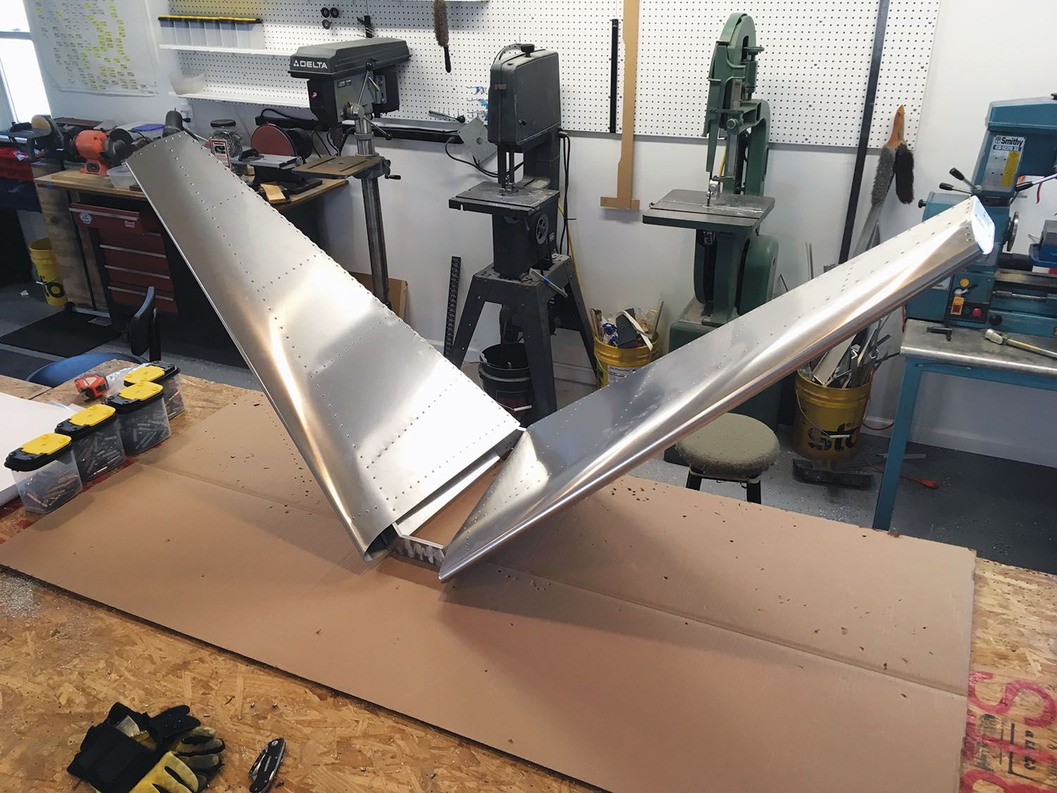
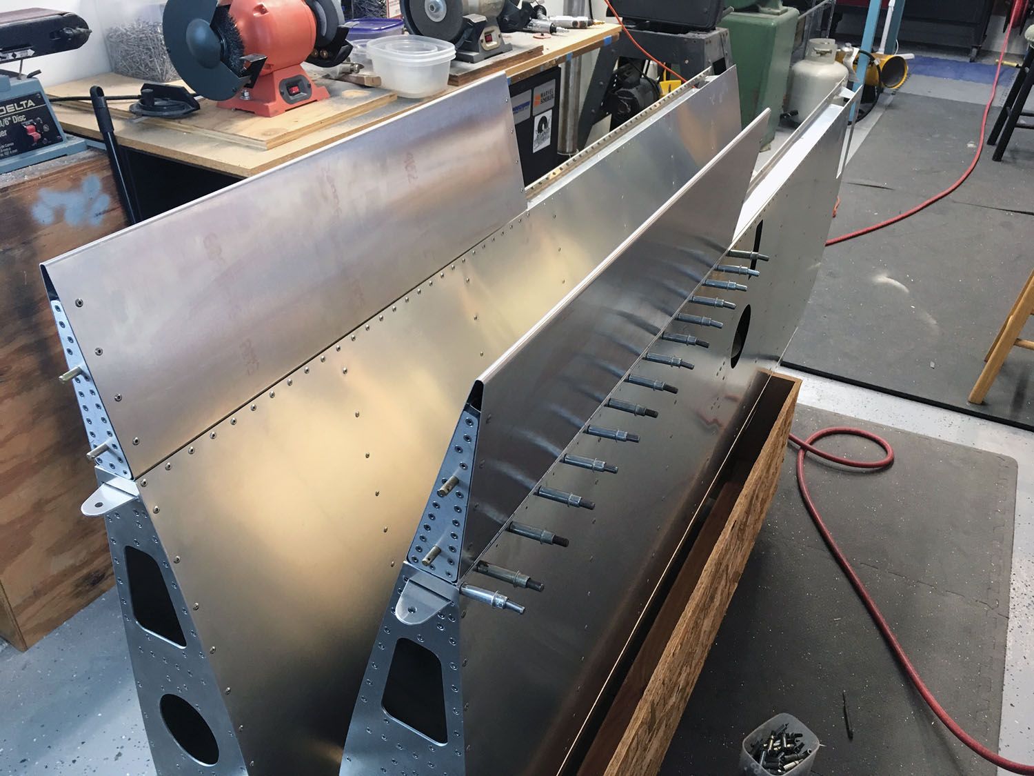
Airframe construction starts with the tail. You can sit in the cockpit and make airplane noises (remember to go “whoosh” instead of sounding like a prop job) any time you feel like it. Just throw a boat cushion in there. But concentrate on that tail and get it right! There are really only two stabilizers to build and two ruddervators—a third less than a standard tail. The good news is that the stabilizer assembly has all prepunched parts, which means you can Cleco the skins and ribs together right from the very start. The assembly becomes a “Y” early on in the build, and this can be just a touch unwieldy in the shop. Make sure you have a workbench where you can hang the stub spar (the part that goes vertically on the back of the fuselage) down over the edge, and it will work better.

One secret to build a scratch-free set of tail feathers: The kit comes in a lot of large cardboard boxes. Cut up some large sections of that cardboard, lay it over your work surface, and build on that. I figured I’d trade it out every once in a while, but the original piece is still there. Putting this clean surface down is important if you’ve already built airplanes on the workbench. You’re going to have lots of leftover holes and scars, and the cardboard gives you a clean surface.
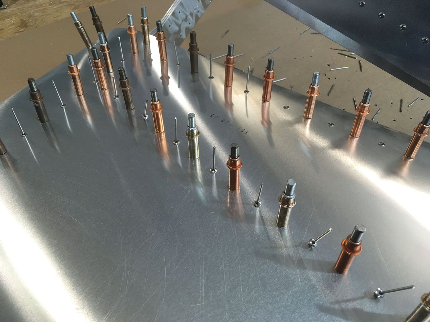
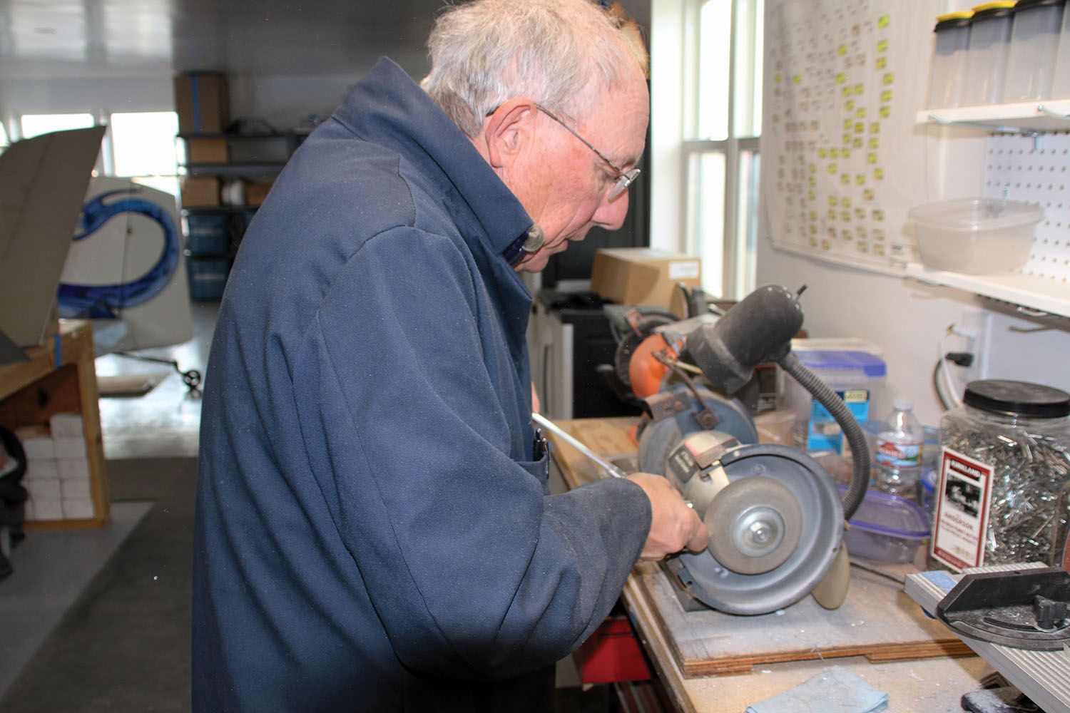
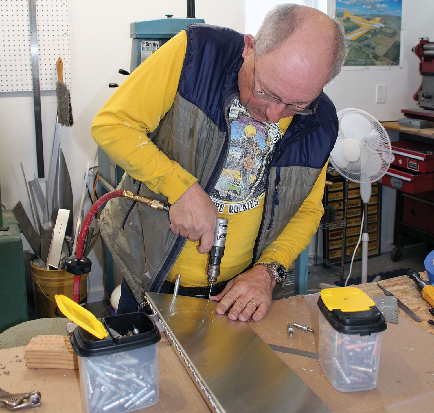
With most of the construction on the SubSonex, you’re going to start out drilling—or at least Clecoing together—everything with #40 holes and silver Clecoes. You’re then going to up-drill to #30 holes and copper Clecoes. If you disassemble, take the time to deburr before you reassemble the parts to be sure that everything fits properly. Round off corners and break edges using Scotch-Brite wheels so that you don’t cut or poke yourself in the future.
Other than those basic rules, there is little else to say about assembling the stabilizer—it just goes together! Make sure you look closely at every drawing. There are clues about how to set hinges and other important stuff you might regret later if you do it wrong.
Control Surfaces
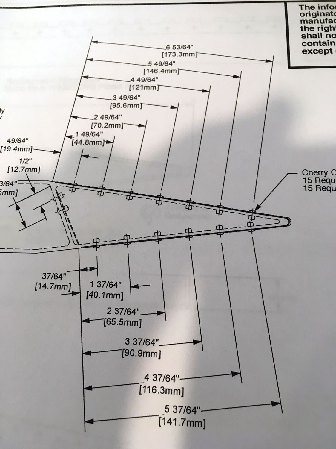
Moving on to the ruddervators, you’ll find that you start with a preformed skin that has to be cut to length, a tip counterweight, and a couple of ribs. Nothing is very hard about this assembly, but read the drawings very carefully and do it a number of times. The outboard end is simple—it attaches to the counterweights at right angles. The inboard end is a bit more tricky—the rib is both swept and tilted. The drawings do their best to show this, but some just don’t see it. I found that cutting the tilt first, then following that with the sweep made it easier to understand.
One way to check that you are getting it right is to mock up the ruddervator and hold it in position relative to the stabilizer. If you’ve done it all correctly, the tab where the pushrod will eventually attach should be planar with the direction of flight. If it’s tilted in any axis, something isn’t trimmed correctly. One other trick you can use to avoid trashing a skin is to trim the inboard end first and get it right—then cut the ruddervator to length at the outboard end (for the counterweight).
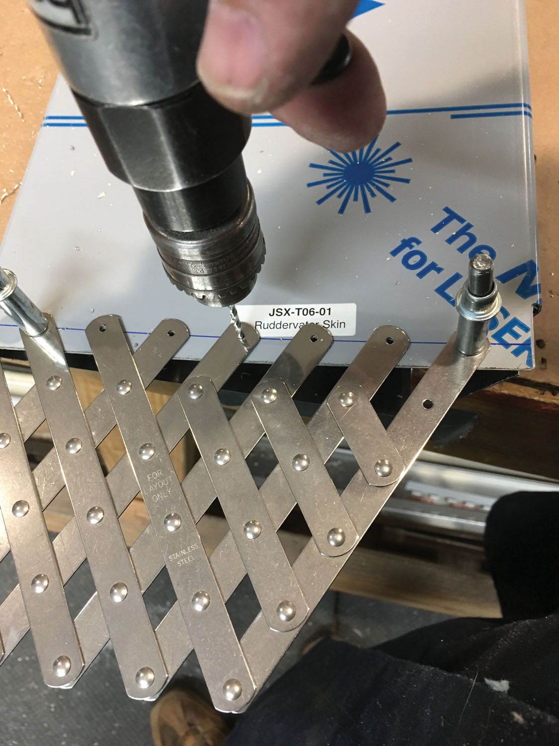
Measuring for rivet holes on the ribs might at first seem intimidating. This is because you’ll see measurements in the drawing down to the sixty-fourth of an inch. Take a deep breath and relax—the critical measurements are the front and back measurements in a row, and they aren’t all that critical. Once you have marked them as best you can, use a rivet fan to place the correct number of rivets in between and you’re done!
As in all building, take your time to visualize the finished part. Pilot-drill, up-drill, disassemble, deburr, reassemble, and rivet! You’ll find that a pop-rivet wedge tool is essential to get in close to some flanges and bellcranks. Other than that, use a pneumatic rivet puller square to the surface and it will go very fast.
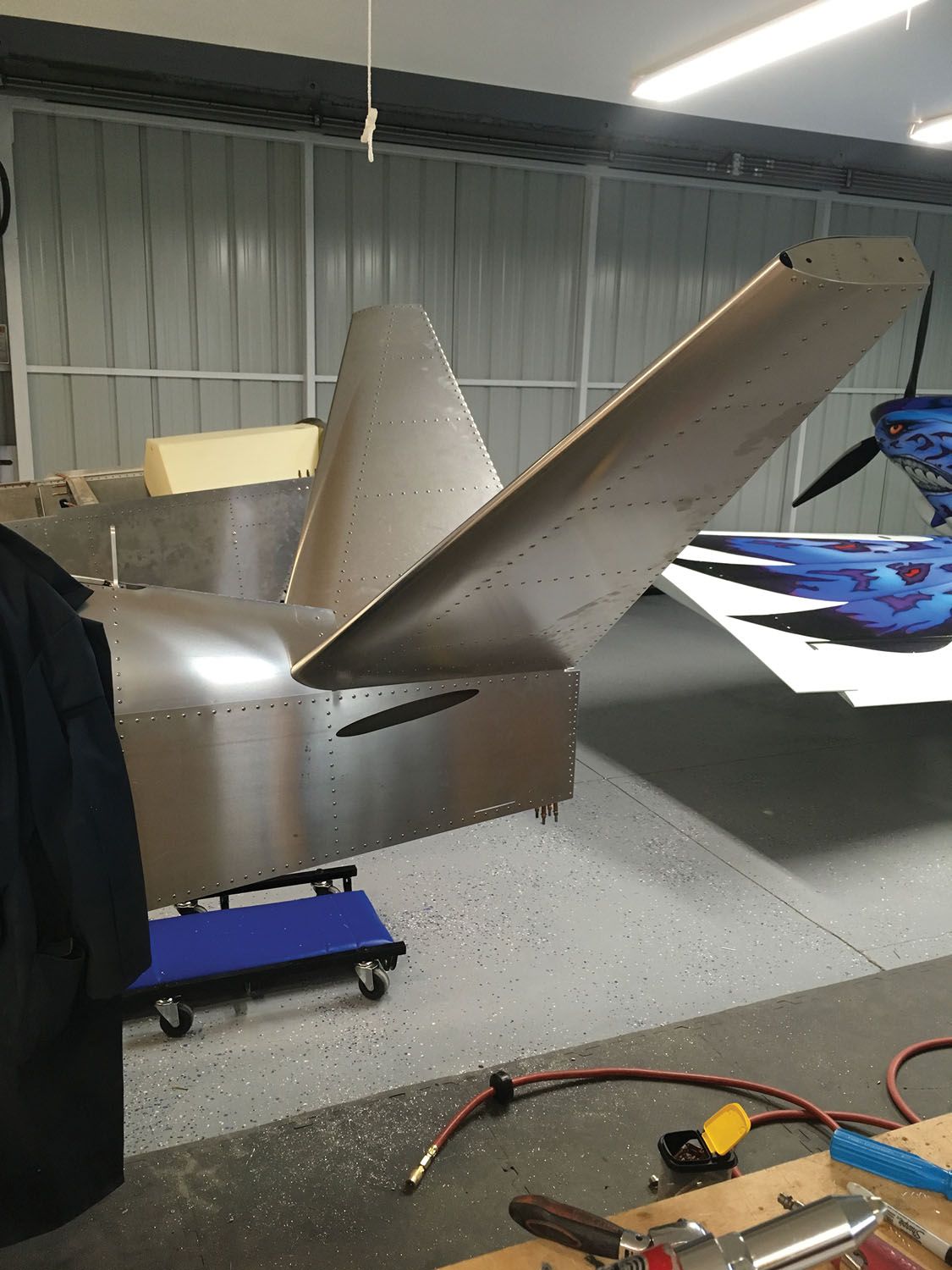
Attaching the ruddervators to the stabilizer is rewarding because suddenly you have a piece of airplane that works! One caution, however, when it comes to hinge pins: The Sonex method of securing hinge pins is to cut the pin shorter than the overall hinge length and drive them in beyond the ends. You then drill and insert tiny cotter pins to prevent them from working their way out. This is an excellent way to keep hinge pins in place, but it can make them very difficult to remove. In fact, since the tip counterweights are physically in line with the hinge pins for the ruddervator, you can only put the pin in from the inboard end, and once you drive it in, there is no way to remove it. Think this through if you are planning on painting with the control surfaces removed—there is no real way to make sure they install properly without putting the hinges in place. But if you want to pull them later, leave a tail of hinge pin exposed so that you can do that—or simply decide that you will paint the airplane with the surfaces installed.
Flaps and Ailerons
When you have a finished tail sitting on the workbench, you should feel good about your work. You’re now half done with the airframe assembly for the jet! Next move on to the flaps and ailerons, all of which have essentially the same cross-section and cord. However, there is that word “essentially.” The difference between flaps and ailerons is that the ailerons are hinged on the top surface, and the flaps are hinged at the bottom. The drawings are accurate, but if you aren’t careful, they can lead you down the road of reversal—sometimes what you think is the top is actually the bottom, and vice versa. It pays to constantly question yourself and think of the big picture to make sure that you are not building something upside down.
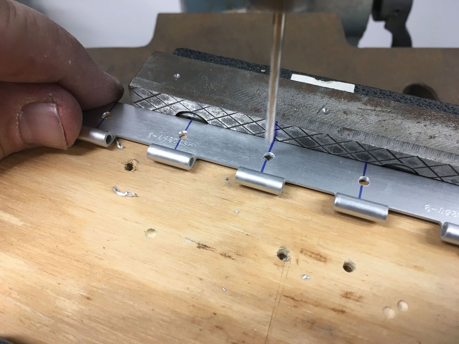
One thing that you’re going to get used to in building the ailerons and flaps (and already will have learned with the ruddervators) is drilling holes for attaching piano hinge. The good news is that all of the holes are measured the same: one-quarter inch from the back edge of the hinge and right in the middle of the hinge loop. The bad news is, you’re going to drill a lot of these holes! It’s tedious measuring and drilling all of these, then center-punching each one…but there is an easier way!
Rather than drawing centerlines and measuring each hole, I built a little jig for my drill press that set the edge distance for each hole precisely. Then all I had to do for each hinge segment was make a quick tick mark along the back edge for each hole (one every inch, starting at a measured point) and run that through my jig, pulling the drill chuck down for each hole. With this predrilled hinge segment, it is easy to match-drill to the control surface.
The flaps are interesting on the SubSonex. There are effectively two of them on each wing, but they operate together, with the inboard operating the outboard via pins that mate up when you install the wing. The pins used are actually clevis pins, and the installation is clever—but it does require a little skill with precision counterboring to get the depth right. This is one place a home milling machine is useful to get a nice square counterbore. What you won’t know until you get to the point of actually installing the wings is that you will want just a little bit of motion so the pin can achieve its final alignment. How much? A little, but not too much…
It pays when building the “wing flippers” to have the wings handy in a stand so you can mock up the hinges and make sure there’s sufficient travel to match the rigging instructions. You get more overall travel if the hinge protrudes father from the wing and less travel if it is tucked in tighter. You’ll want everything to line up to make it look good, so take the time to play with it before committing to rivets. You’ll need a certain amount of faith to believe that the inboard and outboard flap sections will line up, unless you mount the wings while installing the flap hinges, which is certainly a good option if you have room in the shop.
The good news is that once you have finished the flaps and ailerons, you can put the rivet puller on the shelf for a while—there is little else you’ll need it for on the jet until you finish up the belly!
Mounting the Tail
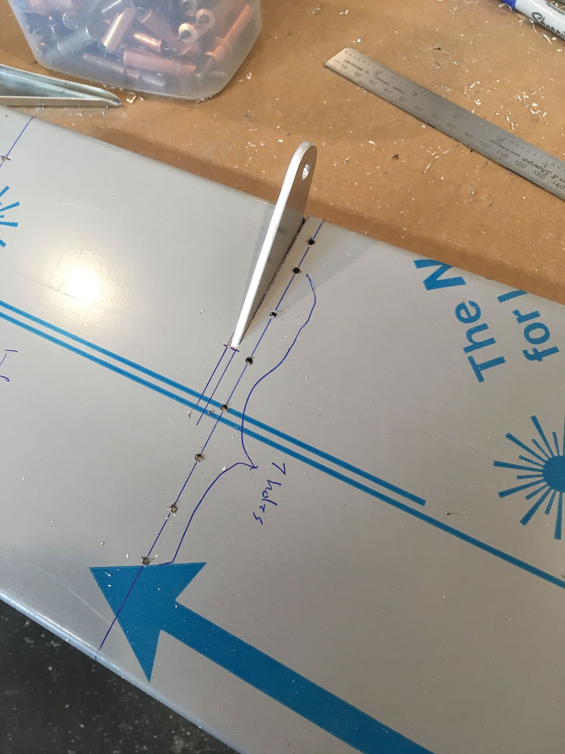
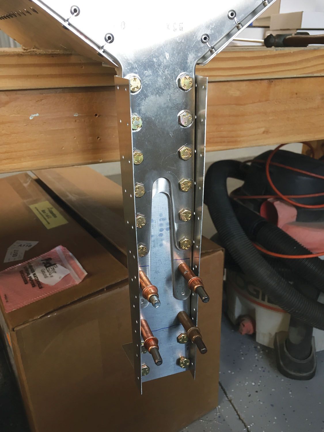
The last major structural construction task for the SubSonex is to mount the tail on the fuselage. Sonex provides some very nicely machined angle bracket for the top and bottom, and they fit very well—but it does take a bit of trial and error to get them in place. You will be drilling some very critical holes for AN3 bolts in the longerons, so pay attention to the dimensions when doing this. I found that in order to transfer the holes accurately, I had to make some templates using hotel key cards. These plastic cards are thin, yet stiff, and make great template material. You could use a credit card, but you still have things to buy for the jet, so don’t use them all up yet!
Sequence is important here, and you want to make sure you don’t rivet anything until you absolutely have to, for disassembly is in your future. I installed the rear bulkhead to the stub of the stabilizer spar on the workbench first, then attached the upper bracket per the drawings and prepunched holes to the tail assembly. I then match-drilled that to the fuselage longerons. The last thing I did was drill the lower angle. You have to do a little bit of prying and pulling to get things installed because of the fuselage taper, but it all goes together really nicely when you get it in place. You’ll want to rivet the aft bulkhead in place before bolting on the stabilizer spars, and this makes for some tight work with wrenches to eventually put in that forest of AN3 bolts—but it all works. Remember, as always, never put anything through the bottom longerons until you have riveted on the belly skin, which happens just before you put fuel in the airplane!
Moving on to Mechanical
Once the tail is on the airplane, you’re pretty much done with the structural building. Yeah, you’ve got some riveting to do for the flap hinges, and the bottom isn’t on (we hope—can’t emphasize that enough), but overall, it looks like an airplane! Congratulate yourself—then get out a set of wrenches and screwdrivers because the mechanical and systems work is about to begin.
First off, get the windshield out of the way. Yeah, they did a great job of installing that at the factory, but it really does need to come off. I suppose if you’re really good at building a ship in a bottle, you can work in the nose area with it in place—but I don’t have arms as long as an orangutan, and you probably don’t either. You’ll waste a bunch of time trying to work with the windshield in place, then eventually you’ll take it off and curse yourself for not doing it earlier, so do it now. Yup, there are a lot of screws and nuts; put them in a bag and set them aside. Note that there are two different length screws. It is obvious why and not hard to put them back in the right place later on.
While you’re removing things, take the canopy off and store it someplace safe. Just remove the bolt holding the cable, then pull the hinge pin. Now that it’s out of your way, you’ll have access to the cockpit from either side. Next, get that fuel tank out of the way. Unbolt the crossbeam that holds it in place and work it out of the fuselage. It’s a tight fit, and the edges of the rear cockpit bulkhead work like barbs to keep it from sliding forward, but it does come out.
Finally, it’s time to get the fuselage bottom skin out of the way. Sonex secures it with a few red-painted aluminum rivets. Drill those out and then fold it forward. It only comes loose up to the main spar, so you can’t take it all the way off. I tucked it carefully under the supports I was using for building and was successful in not crimping it. Once that and the fuel tank are up and out, everything becomes accessible.
One of the advantages of the Sonex drawing/building system is that if you get frustrated or stuck on one part of the build, you can easily switch to another. I tend to work on everything all at once, because I often come up against something I have to think about, so I move on to a totally different part of the airplane while my brain processes a solution to the original issue. This can keep going on, by the way, until my background thought processes are solving problems at a rate that keeps me busy implementing them continuously. This might drive some folks nuts—but it works for me!
Landing Gear
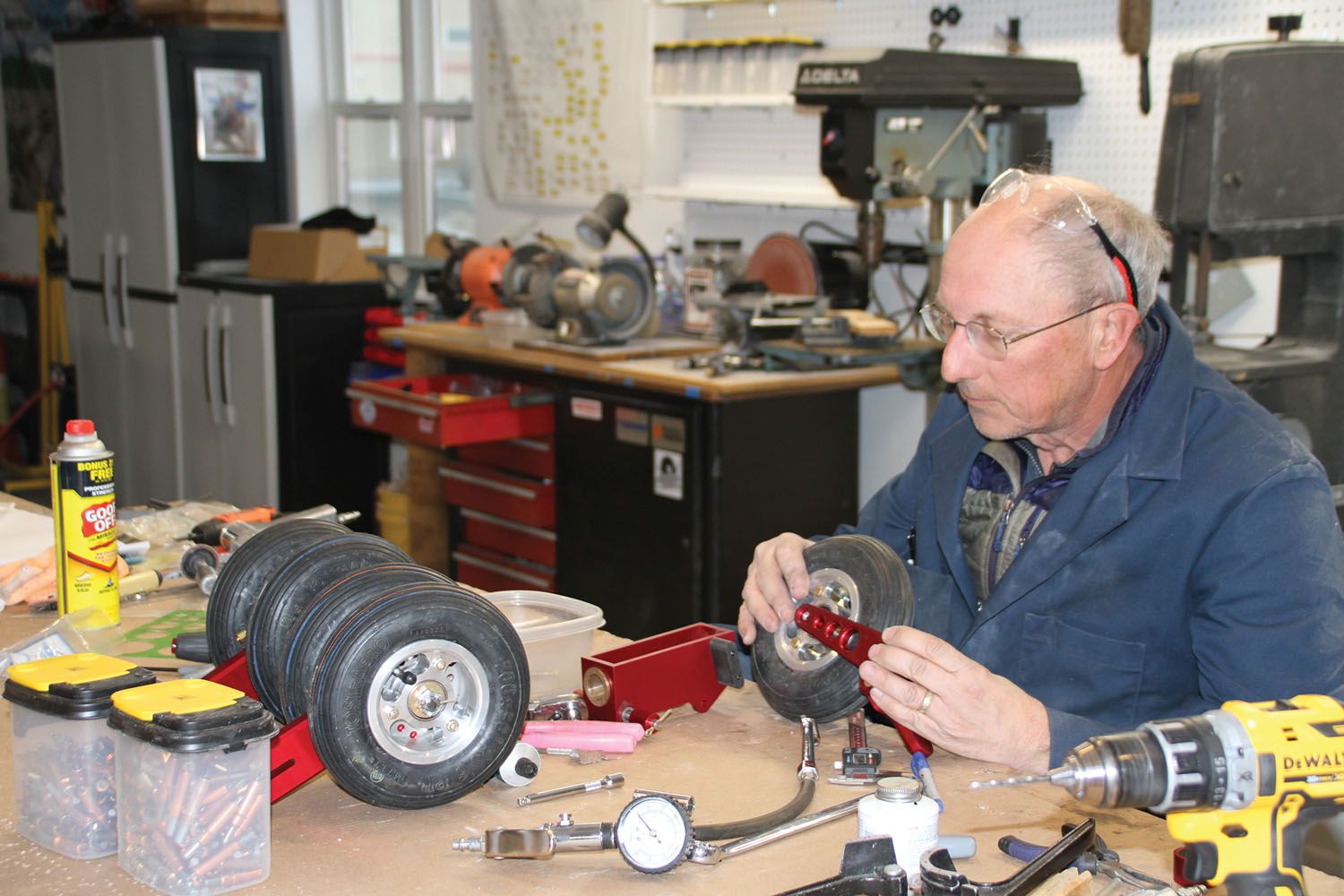
Never having owned a retractable-gear airplane before, I was anxious to get started on the swinging wheels, so I moved from the jet itself to the workbench to start assembling gear legs and wheels. The drawings are mostly exploded views, and all you have to do is put things together, looking for the correct hardware for each assembly, and mark off the drawing bubbles as you go.
The first thing you discover, however, is that clearly the parts are all machined to fit perfectly together before they are anodized. The beautiful red color—while pretty—is a few microns thick, meaning some nesting parts simply will not fit together. I used a combination of emery cloth (for outside diameters) and sanding drums on rotary tools (for inside diameters). It is pretty obvious where you need to remove anodizing to get things to fit. Don’t be too aggressive, however. You don’t want things sloppy. This will hold true when assembling the control column as well.
Before you can assemble the main wheels, you have to drill and countersink the brake discs. This is probably one of those items they leave for the builder to meet the 51% rule, but be warned—these are stainless, and if you get them hot by using a fast tool, they work harden to the Rockwell hardness of diamonds! Go slow, use the speeds and pressure appropriate for stainless, and the work will go easily.
There are five wheels that need to be assembled altogether. You’ll get good at it or die trying! Actually, they are quite easy to put together, but make sure you don’t pinch the tube between the wheel halves. Because the tires are so small, a very tiny amount of air changes the tire pressure significantly, so don’t put a long burst in or you’ll be over 100 psi instantly. Go slow and get to the specified pressure. In an hour you’ll have a stack of wheels and be ready to assemble trucks!
The main gear trucks are also the brake modules. Assemble them per the drawing, but before you install the brake pistons and pucks, inspect to make sure that they are all connected with drilled holes in the bodies—some assemblies have come from the factory improperly drilled. The diagonal holes from the lower corners should go all the way to the upper puck cavities, so check them!
I used a little Dow Corning #4 lube on the O-rings on the pistons and then popped them into position. Install the axles and wheels with the specified hardware, and you have airplane assemblies, right there on the workbench!
The nose gear assembly goes together well in a similar fashion—just remember to get the clearances right for smooth, no-slop action. A set of little washer wrenches help to get all those tucked-in washers in place. Don’t be afraid to substitute thin or thick washers as required to make it all fit; the drawings are a starting point.
Once I had the nose gear assembled, I couldn’t wait to get it installed—but I should have. It can be a bit painful installing the necessary bolts in the leg wells that attach the gear, so once you get those in, you don’t want to have to take it all back out. But…in order to install the nose gear door hinge, you really don’t want the gear in the way. Do yourself a favor—install the door hinge first!
The landing gear is operated pneumatically, using three actuators that alternately push or pull the gear up and down. The actuators come with Hall effect sensors that detect the position of the piston and are used to drive the cockpit lights for gear up or gear down. Pneumatic pressure is conveniently about shop air pressure—90 to 120 psi—which is very convenient if you want to watch things happen well before you have the full air system installed! In my case, it was a simple matter to dive into my pneumatic quick-disconnect parts kit, plumb some temporary nylon tubing, and watch the nose gear (and eventually the mains) go up and down at my command. It’s a cheap and easy victory that means little, but it makes you feel good.
Snaking all of the components for the gear retraction systems into place will make you wish you had small flexible hands, but a spouse or child can usually be pressed into service if need be. Expect to use discretion on bolt lengths, as elsewhere. I didn’t encounter any bolts that were excessively long, but a number of spots required an additional dash number.
When you start playing with the landing-gear pneumatics, you’ll no doubt want to start running plumbing. This is good—but think ahead for maximum clearance between the plumbing (nylon tube) and the wheels. Some early aircraft had problems with the spinning nosewheel rubbing a hole through a tube, so always route for maximum clearance. I plumbed the nose and main gear into the fuselage early on and connected them together with spare tubing so that I could impress visitors with the up/down/up/down any time I wanted.
Other Systems
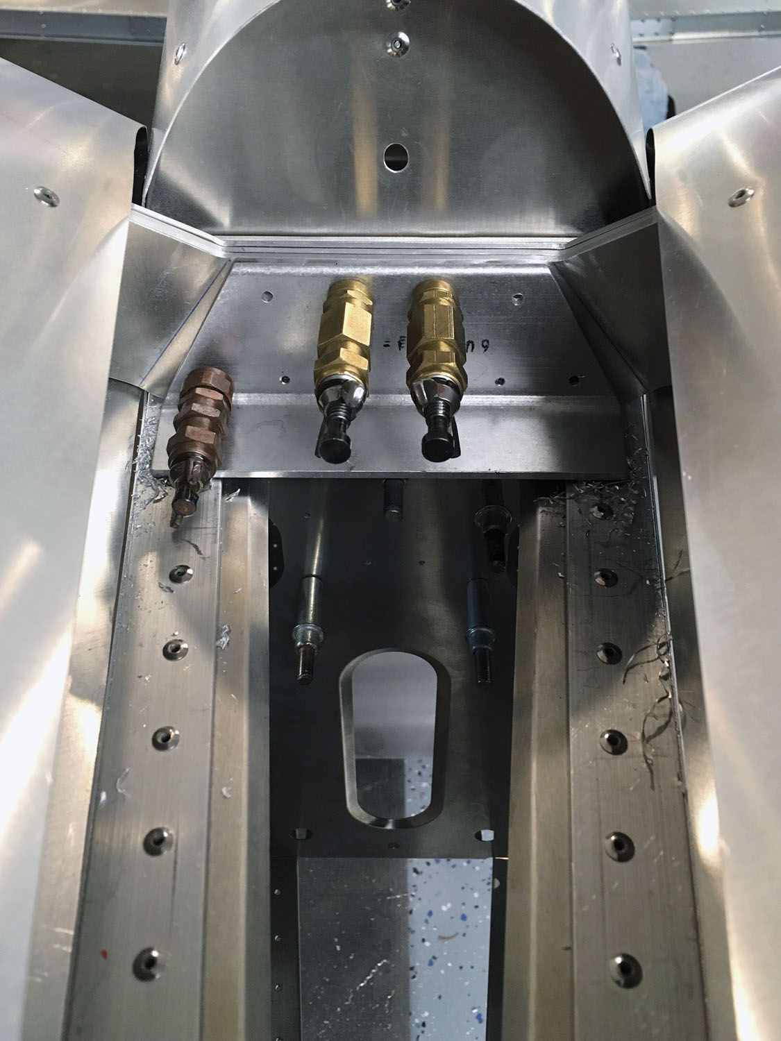
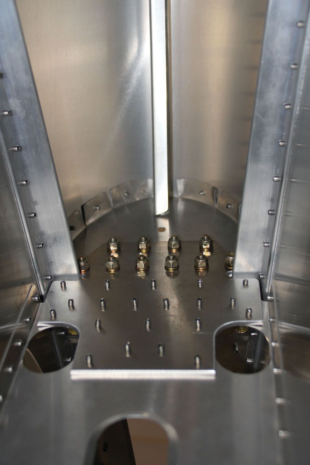
For a jet aircraft, the systems on the SubSonex are remarkably few and simple. Aside from the landing gear, you have the fuel system, which is simply a tank, header tank, and pumps. The flaps are either manual or electric (I went with electric) and are dirt simple—pushrods and a linear actuator, with a switch and power. The stock trim is mechanical, with a worm gear knob pulling on a cable that stretches a spring. Again, like the flaps, I preferred electric, so I designed a simple system using a Ray Allen servo to pull on the spring through an idler arm (to increase the throw). Finally, the air system for the gear fits on the back of the main spar and features a tank and two 24-volt pumps in parallel to keep the system pressure up.
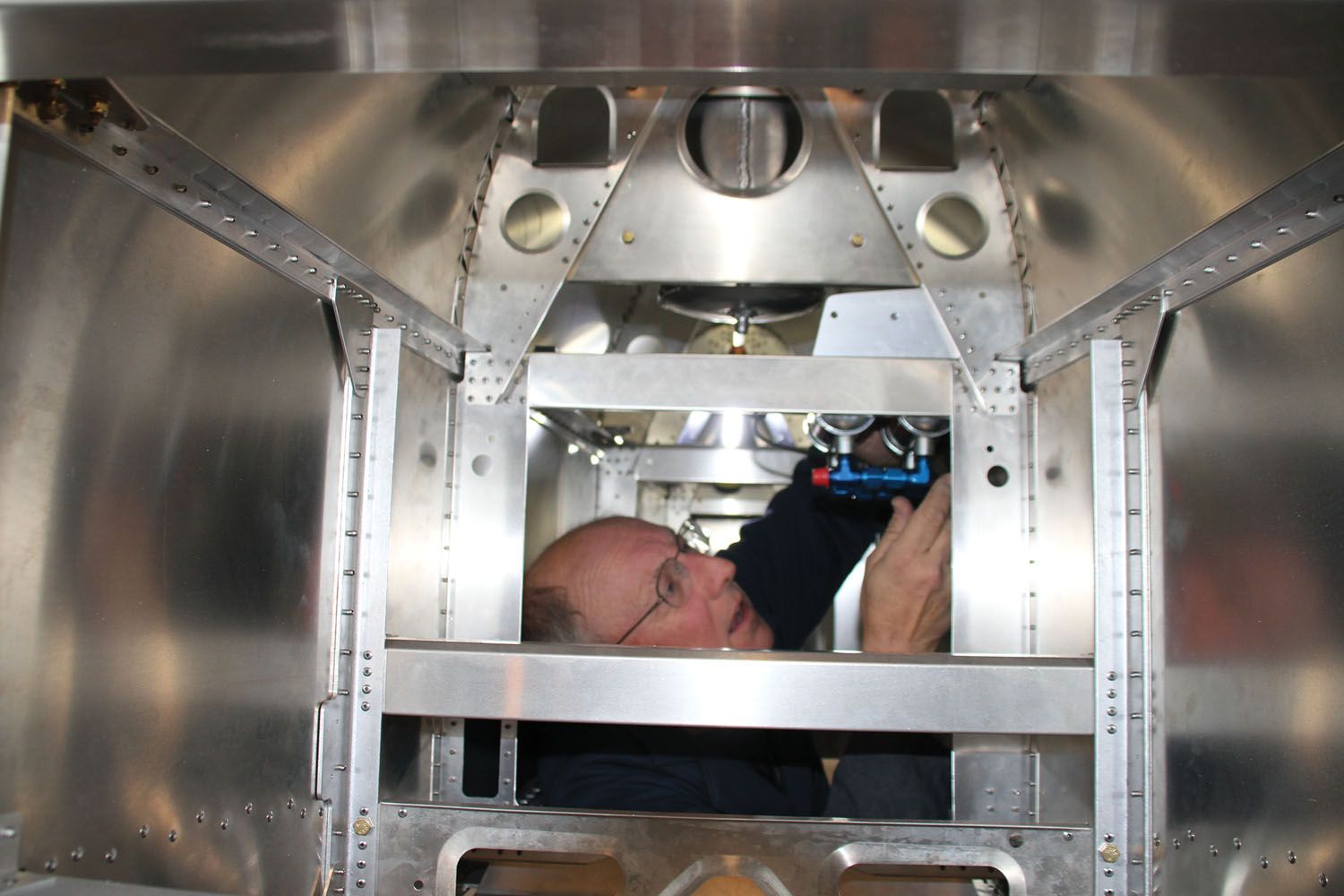
Like for the rest of the kit, there really aren’t any instructions for any of these. You look at the drawing and put things together as shown. If you need step-by-step hand-holding, this is not the kit for you. But it doesn’t take a great deal of experience and/or creativity to figure it out either. Sequencing the various build steps is probably the most important thing that experience will teach. Building from the inside out is the mantra to use. Anything in the space where the fuel tank goes is first, and you work your way out from there. The jet is just too tiny to do anything else!

One other system to mention is the control system—it really is just pushrods for roll and pitch, plus cables to the rudder pedals for yaw. The control column mounts to the right side of the cockpit wall, and it is important to pay attention to the angles. The two stand-off mounts are tapered to fit the changing dimensions of the cockpit walls and can only go together correctly one way. But you can force them together incorrectly, so keep your eyes open and figure it out. You’ll also have to remove powder coat from the column and anodizing from the stand-offs until you get a smooth control system. It takes time, but it is worth it.

Assembling and installing the rudder pedals is a task that will tax your back. Bending over the edge of the nose and working through the windshield hole looks easy, but it’s not. There are some cotter pins and nuts to install that will have you inventing new bad words—but once they are installed, you’re done! There are actual turnbuckles under the pilot’s thigh area that are used to put a little tension on the rudder cables, but you’ll have to figure out how much tension on your own; no spec is given. And if you haven’t safety-wired a turnbuckle in years, you’ll have to look that up as well.
Overall, the mechanical systems for the jet are straightforward and simple. The only real complications come from the compact space in which you have to work and the need to figure things out on your own. But it’s not rocket science—even though you are building a jet!
Photos: Richard VanderMeulen, Louise Hose and Paul Dye


Boxing Day")


