For the past few months we have been exploring all of the factors that affect the physical position of the center of gravity (CG) of the airplane. We now turn our attention to the aerodynamic aspects of making the airplane balance.
Once the CG range of the airplane is known, the designer must then ensure that the airplane has acceptable flying qualities for any CG position at which it might be flown. For most airplanes this requires a bit of a trade-off between getting the aerodynamic characteristics right and specifying limits on the loading. For many airplanes it is physically possible to load the airplane outside its acceptable limits.
The designer’s goal is to give the airplane a wide enough range of acceptable CG positions so that the loading limitations do not unduly restrict the usefulness of the airplane.
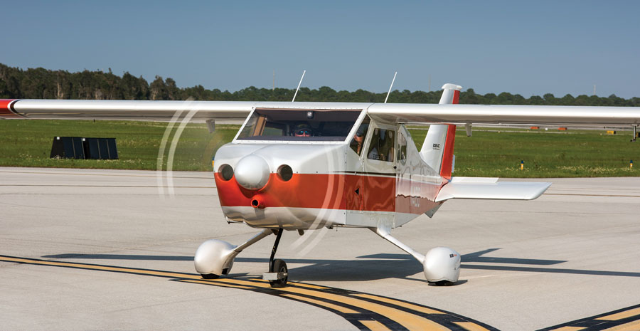
The forward CG limit is set by the available nose-up pitch control power of the elevators (or stabilator), while the aft CG limit is typically determined by stability considerations.
It’s also very desirable to make sure that most “normal” loadings fall well within acceptable CG limits. In general, pilots don’t do weight-and-balance calculations before every flight. While this might not be good practice, the designer must accept that most pilots only calculate weight and balance if they are loading the airplane in (what to them is) an unusual manner or if they have good reason to be concerned about the CG or gross weight. Accordingly, it’s desirable to have the CG fall well within limits for loadings with most expected combinations of “normal” weight people in the seats and fuel states from empty to max fuel.
Aerodynamic CG Limits
The acceptable range of CG positions is set by stability and control considerations. The aft limit is typically determined by stability considerations while the forward limit is set by the available nose-up pitch control power of the elevators.
Mean Aerodynamic Chord
In all discussions of longitudinal stability and control, an important geometrical parameter is the mean aerodynamic chord (MAC) of the wing. Aerodynamic characteristics of a configuration are usually tabulated in the form of nondimensional coefficients that are referenced to geometric scaling parameters of length and area. For most airplanes, the reference quantities are those of the wing. Wing area is easy to determine. The chord of the wing is used as the reference length for pitching-moment and pitch-stability parameters (pitching-moment coefficient and static margin).
Early airplanes almost all had constant-chord wings, so the choice of the appropriate chord to use in calculations was easy. As tapered wings and other more complex planforms emerged, the proper chord to use was more problematic. The concept of MAC was developed to clear up this uncertainty. The MAC is defined as the chord of a rectangular wing having the same longitudinal characteristics as the actual wing.
We will go into how to determine MAC in a future article on wing design, but for now it is important to note two things:
The MAC (both position and length) is the reference chord for all pitching-moment and pitch-stability analysis.
The MAC for a tapered wing is not the same as the geometric average chord of the wing that would be determined by dividing wing area by wingspan.
Neutral Point
Every airplane has a CG position at which it will be neutrally stable in pitch. When the CG is at this position (called the neutral point), pitching moment does not change with changing angle of attack.
Static Margin
The pitch stability of the airplane is expressed in terms of the position of the CG relative to the neutral point. If the CG is forward of the neutral point, the airplane will be stable in pitch. If the CG is aft of the neutral point, the airplane will be longitudinally unstable.
The static margin is defined as the fore-and-aft distance, expressed in terms of percent of the MAC, from the CG to the neutral point. Static margin is positive (stable) if the CG is forward of the neutral point and negative (unstable) if the CG is aft of the neutral point. For example, if an airplane is 5% stable, the CG is 5% of the MAC ahead of the neutral point.
Aft CG Limit
To fly safely the pilot must be able to control the pitch attitude and angle of attack of the airplane. General aviation airplanes do not have computer-controlled augmented flight-control systems, so it is left to the pilot to control the airplane directly.
The aft CG limit is the most aft CG position at which the airplane has acceptable pitch stability to be flown safely. This minimum stability level is not zero static margin. While it might be possible for a pilot with good reaction time to keep a neutrally stable to slightly unstable airplane under control for a while, the high workload this requires makes it unacceptable for general use. Accordingly, the airplane will be required to have some positive static margin at all times, and the aft CG limit defines the smallest acceptable static margin for safe flight. This value is somewhat configuration-dependent, but a good starting point for preliminary design is to set the aft limit at 5% static margin. Where on the MAC this aft limit falls is a function of the configuration and most directly of the geometry of the horizontal tail and tail arm.
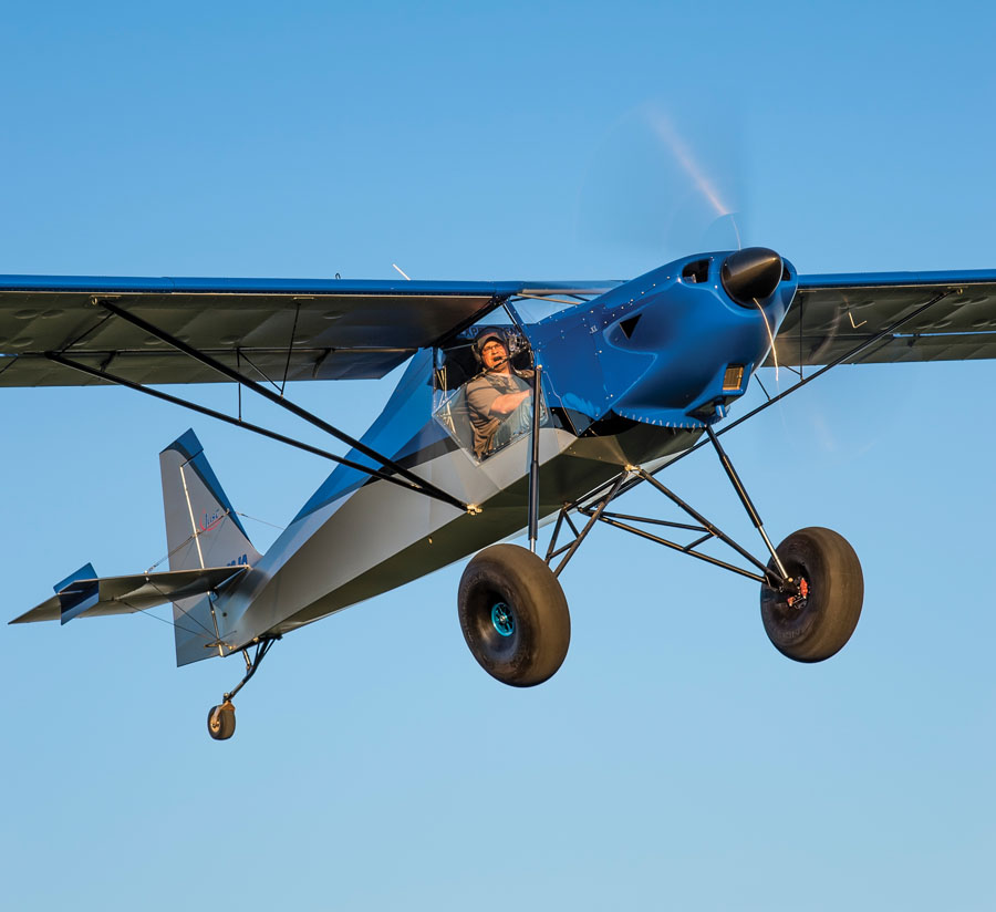
Takeoff can sometimes set the forward CG limit. In order to lift off, the elevators must produce enough nose-up moment to lift the nose and rotate the airplane to its liftoff angle of attack.
Forward CG Limit
If the CG is forward of the aft limit, the airplane is stable enough in pitch to be flyable. The next issue we must consider is controllability and trim. As the CG moves forward, the airplane becomes more stable. This means that for a given angle of attack, the airplane will generate more nose-down pitching moment that must be trimmed out by the elevators in order to maintain trimmed, level flight.
In-flight configuration changes can also generate increasing nose-down moments. If the airplane has retractable landing gear, extending the gear will cause a nose-down moment because the drag of the extended gear acts well below the CG of the airplane.
Deflecting flaps will also cause a change in pitching moment. Which way is dependent on the details of the airplane’s configuration, but many airplanes exhibit a nose-down pitch due to flap deployment.
At some point, the combination of these effects produces enough nose-down moment that all of the nose-up pitch command capability of the elevators is needed to trim it.
The most forward allowable CG in flight is usually set by the ability of the elevators to trim the airplane to its stall (maximum lift) angle of attack with the flaps and gear configured in their most nose-down moment producing configuration. For most airplanes this will be gear-down, full-flap. If the CG is forward of this limit, full-aft stick will be insufficient to trim the airplane to maximum lift.
Takeoff can also sometimes set the forward CG limit. In order to lift off, the elevators must produce enough nose-up moment to lift the nosewheel off of the runway and rotate the airplane to its liftoff angle of attack. It’s generally considered necessary for the pilot to be able to lift the nose at an airspeed below stall speed to ensure the ability to perform a smooth, positive rotation to set the airplane to a flight attitude as it reaches the desired liftoff speed. If the elevators cannot do this, liftoff speed will increase to a speed at which the elevators can lift the nose, and there is a danger of an abrupt rotation and hop-off as the airplane rotates suddenly at a high speed on the runway. More than one early flight-test accident has been caused by this phenomenon.
At one time U.S. regulations for certified airplanes required it to be possible to lift the nose at 85% of stall speed. I have not confirmed that this is still the case, and homebuilts are not required to meet FAR standards, but this is a good starting point for preliminary design.
The forward CG limit of the airplane as a whole will be the most forward CG position that meets both the in-flight and takeoff rotation requirements.









The Wind Tunnel series of aircraft design articles are my absolute favorite aviation articles in any magazine every month. Every time I see a new issue of Kitplanes, I immediately flip to the back to check for the next article.