![]() When trimming the elevator counterweights of a Van’s RV-14 kit, I modified one of the weights incorrectly. This led to the holes in the weight not aligning with the elevator tip-rib holes, so the weight could not be installed. My first thought was to order a replacement part, but since the weight was ruined anyway and it’s not a structural component, I decided to see if I could fix it. My idea was to fill the existing holes with lead and shift the holes by drilling new ones in the correct places.
When trimming the elevator counterweights of a Van’s RV-14 kit, I modified one of the weights incorrectly. This led to the holes in the weight not aligning with the elevator tip-rib holes, so the weight could not be installed. My first thought was to order a replacement part, but since the weight was ruined anyway and it’s not a structural component, I decided to see if I could fix it. My idea was to fill the existing holes with lead and shift the holes by drilling new ones in the correct places.
Before going further, think of all the possibilities that could cause molten lead to go flying in the shop. It might be something obvious such as not clamping the counterweight tightly, or it could be something unexpected like a wasp sting in the middle of the process. Be careful—and remember all the warnings that mothers give about playing with fire!
 OK, let’s get started. Because the ends of the lead weights are shaved to fit the tip-rib profile, there’s scrap material left over. A quick test with a propane torch revealed that the lead scrap would easily melt.
Figure 1 shows a piece of scrap lead placed over the holes to be filled. Carefully apply heat. Try to keep the heat focused on the lead to be melted—you don’t want to melt the underlying weight here!
The melted lead should puddle and ooze, filling the screw holes and bolt-head recesses (Figure 2). Notice the burn marks on the wood. Be sure to be aware of anything behind the flames.
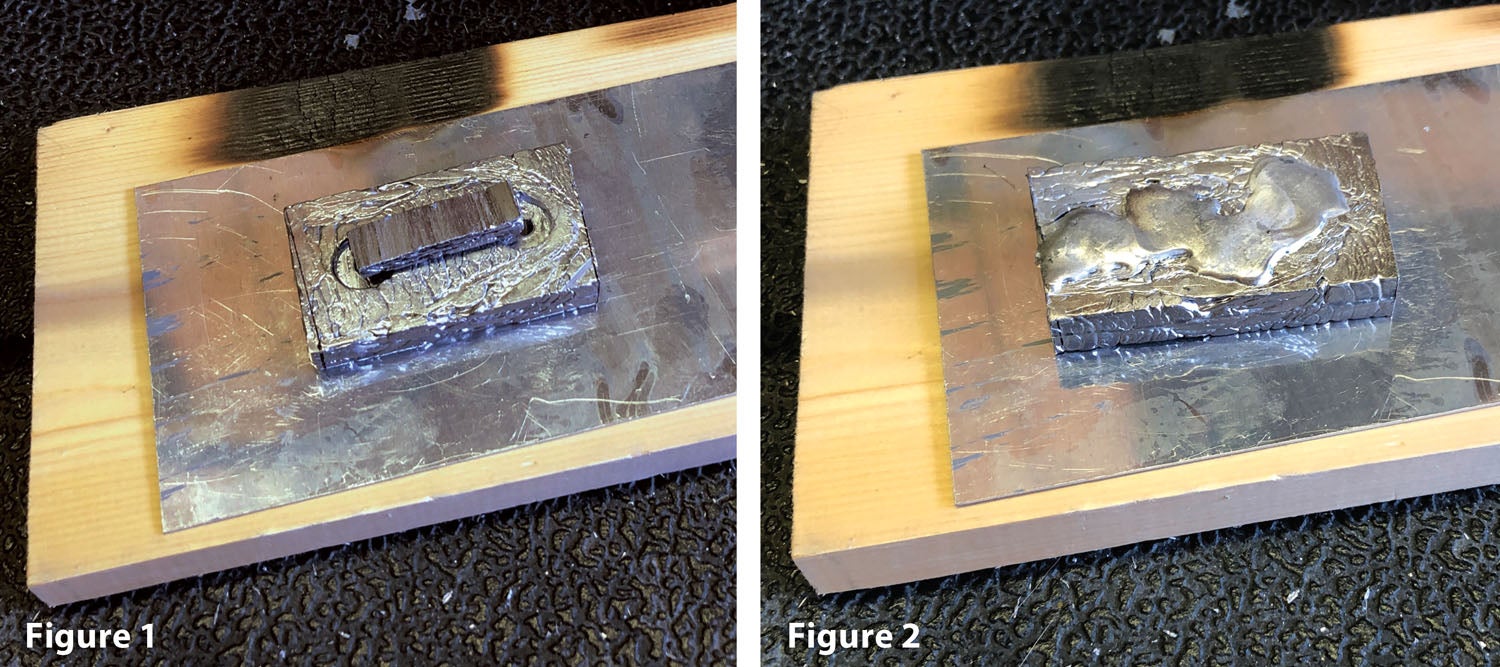
My “forging” was successful, but in hindsight it might have been better to somehow focus the molten lead into the screw holes. Something like a piece of scrap metal with a hole in it might work.
The next step is to mate the damaged weight with its sibling. The weights should be “mirrored.” Notice the pair of clamps in Figure 3 to keep the siblings aligned as well as a larger clamp to keep the whole contraption in place while drilling. Using the undamaged weight as a guide, match drill the new holes using a #12 bit for AN3 bolts.
Mark the side of the weight where the bolt-head recesses are needed (Figure 4). The siblings are again mirrored, so there’s no mistake about which side is the correct one. On the bottom weight, the recesses face down; on the top weight they face up.
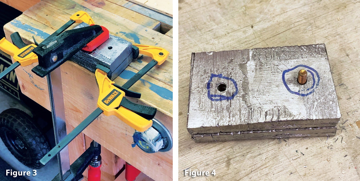
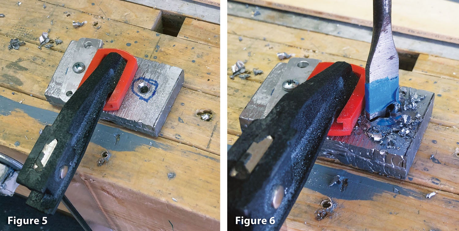
Figure 5 shows the weight that needs to be drilled securely clamped to the bench. A vise might also work. Notice the left side is screwed to the bench with a scrap piece of metal as a hold-down. The clamp and hold-down will prevent the weight from spinning while drilling. If you use a screw in this fashion, make sure it will fit without enlarging the holes you previously drilled.
The bolt-head recess diameter was measured, and a 5/8-inch spade bit looked like it would work (Figure 6). Grind the sides of the point on the spade bit so it fits inside the hole and doesn’t enlarge it. You can place some tape on the bit to mark the approximate depth of the hole.
Go slowly and apply light pressure. Too much pressure will cause the bit to grab the workpiece. A cordless drill works well here.
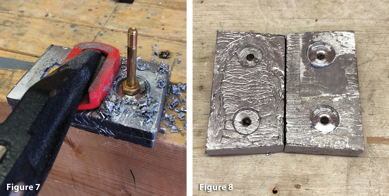
Check the depth periodically. You can eyeball the depth by inverting a bolt head in the recess (Figure 7). More precise builders can also use the depth gauge on a set of calipers.
Figure 8 shows a pair of finished weights. The one that’s been repaired is on the right. After the holes and bolt-head recesses are drilled, you may want to weigh the pairs of weights and adjust as necessary so they are close. I’m not sure how critical this is. Mine were within 5 grams of each other; in the not-a-Swiss-watch category of building, I thought it was good enough. As you can see in the top photo on the first page, once installed, the repaired counterweight looks fine.